

Page 1

OPERATING INSTRUCTIONS
AIR NAILER
MODEL: F50F
PARTS LIST
Refer to the Exploded View Drawing for the location of parts listed below
6
ITEM
1
2
3
4
5
6
7
8
9
10
11
12
13
14
15
16
17
18
19
20
21
21A
22
23
24
25
26
27
28
28A
28B
29
30
31
32
32A
33
34
35
SCR EW
BUS HIN G
EXH AUST CO VER
DESC RIPTI ON
DESC RIPTI ON
WASH ER
SCRE W
WASH ER
CYLI NDER CAP
GASK ET
VALV E SEA L
SPRI NG
O-RI NG
O-RI NG
VALV E
O-RI NG
STOP PED W ASHER
COLL AR
O-RI NG
O-RI NG
PIST ON AS SEMBL Y
CYLI NDER
O-RI NG
O-RI NG
BUMP ER
BODY
JOIN T GUI DE
SPRI NG PI N
SAFE GUID E
SPRI NG
SAFE BRACK ET A
SAFE BRACK ET B
SAFE BRACK ET C
SEAL
TRIG GER V ALVE HEAD
SPRI NG
TRIG GER V ALVE STEM
O-RI NG
O-RI NG
TRIG GER V ALVE GUIDE
SPRI NG
36
37
38
39
40
41
42
43
44
45
46
47
48
49
50
51
52
52A
53
54
54A
55
56
57
58
59
60
61
62
63
64
65
66
67
68
69
70
71
ITEM
TRIG GER S PRING
SPRI NG PI N
TRIG GER
TRIG GER
WASH ER
SLEE VE
LATC H ASS EMBLY
SPRI NG PI N
PLAT E
SPRI NG PI N
SCRE W
FRON T PLA TE
SCRE W
DRIV E GUI DE
PIN
MOVA BLE M AGAZI NE
FEED ER SH OE
FEED ER SE T
SPRI NG
RAIL
PIN
FIXE D MAG AZINE
SCRE W
STOP PED P LATE
LOCK
SPRI NG
SCRE W
BUSH ING
JOIN T GUI DE
NUT
SUPP ORT
WASH ER
SCRE W
NUT
SOFT GRIP SLEE VE
O-RI NG
END CAP
AIR PLUG
Page 2
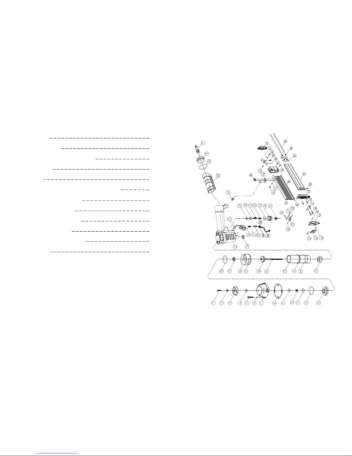
5
EXPLODED VIEW DRAWING
CONTENTS
SUMMARY
SPECIFICATIONS
SAFETY WARNINGS & CAUTIONS
UNPACKING
SETTING
CONNECTING THE TOOL TO AN AIR SUPPLY
LOADING THE FASTENERS
OPERATING THE TOOL
REGULAR MAINTENANCE
TROUBLE SHOOTING
EXPLODED VIEW DRAWING
PARTS LIST
1
1
1
2
2
3
3
3
3
4
5
6
Page 3

Characteristic
Minimum Operating Air Pressure
Maximum Operating Air Pressure
Nail Length Range
Nail Size
Nail Capacity
Air Inlet
Air Consumption
Tool Weight
Value
60 PSI
100 PSI
3/4" -- 2"
18 Gauge
100
1/4" NPT
1.8 CFM
3.1 lbs
1
SPECIFICATIONS
SUMMARY
You will need the instruction for the safety warning and precautions, assembly instruction, operating and maintains
procedures, part s list and diagram. Keep your invoice with this instruction. Write the invoice number on the inside of
the front cover. Keep the instruction and invoice in a safe and dry place for future reference.
READ ALL INSTRUCTIONS BEFORE OPERATING THE TOOL
1. Lubricat e as instructed.
2. Check air supply.
3. Replace spring.
4. Repl ace damaged int ernal
parts.
1. Replace joint guider.
2. Use the r ecommend ed and
undamaged faste nerls.
3. Tighten scr ews.
4. Replac e piston assembly.
1. Replac e piston assembly.
2. Adj ust to ad equ at e ai r
pressure .
3. Check cylindre cap spring for
broken c oils or reduce d length.
Check i f exhaust port of cylinder cap is restr icted.
1. Repl ace bumper or pusher
spring.
2. Cl ean drive channel of fr ont
plate.
3. Check hose and co mpressor
fittings.
4. Replace O-ring or lubricate.
5. Replace O-r ing.
6. Repl ace seal.
4
TROUBLE SHOOTING
PROBLEM
Air leaking at
Trigger area
PROBLEM CAUSE
SOLUTION
1. O-ring in trigger valve are damaged.
2. Trigger valve head are damaged.
3. Trigger valve st em, seal or O-ring a re
damaged.
1. Check and replace O-ri ng.
2. Check and repl ace trigger
valve head.
3. Check and repl ace trigger
vlave stem, seal or O-r ing.
Air leaking between
body and front plate
Damaged piston O-ring or bumper.
Air l eaking betw een
body and cylinder cap
1. Screw loose.
2. Damaged seal.
1. Tighten screws.
2. Check and replace seal.
Blade driving fastener
too deeply
1. Worn bumper .
2. Air pressure is too higher.
1. Replac e bumper.
2. Adjust the air pressur e.
Check and replace O-ring or
bumper.
Runs sl owly o r has
power lo ss
Tool skip a fasteners
Fasteners are jammed
Tool will not d rive
down tight
1. Insufficient oil.
2. Insufficient air supply.
3. Broken spring in cylinder cap.
4. Exhaust port in cylinder cap is blocked.
1. Worn bumper or d amaged spring (53).
2. Dirt in front plate.
3. Inadequate airflow to tool.
4. Worn or dry O-ring on piston.
5. Damaged O-ring on trigger valve.
6. Cylinder cap seal leaking.
1. Joint guider is worn.
2. Fa steners are wro ng size or d amaged.
3. Magazine or front plate screw s are loose.
4. Blade in pi ston assembly is damaged.
1. Worn blade in piston assembly.
2. Lack o f power.
3. Slow cycling and loss of power.
STO P USIN G THE TOOL IM MEDIATE LY IF ANY OF THE FOLL OWING PROB LEMS
OC CUR. SER IOUS PERS ONAL INJURY COU LD O CCUR. ANY REPAI RS OR R EPLA CEMENTS MUST B E DONE BY A QUALIFIED PERSON OR AN AUTHO RIZED SERVICE CENTER
ON LY.
SAFETY WARNINGS& CAUTIONS
1. KEEP WORKING AREA CLEAN. Cluttered areas invite injuries.
2. DON’T ALLOW CHILDREN KEEP AT THE WORKING AREA. Don’t let them handle the tool.
3. DO NOT OPERATE THIS TOOL IF UNDER THE INFLUENCE OF ALCOHOL OR DRUGS. Read
warning label on prescriptions to determine if your judgment or reflexes are impaired while taking drugs. If there
is any doubt, do not attempt to operate.
4. USE SAFETY GLASSES. Safety glasses should conform to ANSI Z87.1 specifications. Before operating,
wear safety glasses against flying debris from the front and side. Safety glasses should be worn when loading,
operating, unloading or servicing this tool.
5. USE EAR PROTECTION. The working area may be exposed to high noise levels that can lead to hearing
damaged.
6. NEVER USE OXYGEN COM BUSTIBLE GASES, BOTTLED GASES OR HIGH PR ESSURE
COMPRESSED GAS AS A POWER SOURCE FOR THIS TOOL. The tool may explode and cause
serious injury.
7. DRESS SAFELY. Protective gloves and nonskid footwear or safety shoes are recommended when working
with and operating this tool. Don’t wear loose clothing or jewelry. They can get caught in moving parts. Also,
wear a protective hair covering to prevent long hair from getting caught in the tool.
8. DO NOT FIRE TO HARD MATERIALS. Do not attempt to shoot toward hard or brittle material such as
concrete, steel or tile.
9. WHEN OPERATING TOOL. keep the proper footing and balance to avoid damaged resulting from losing
balance.
10. CHECK DAMAGED PARTS. Before using tool, carefully check if there is any part damaged.
11. REPLACE PARTS AND ACCESSORIES. Only allow use same replacement parts while servicing. Ap-
proved accessories and replacement parts are available.
12. KEEP ALERT. Watch what you are doing. Use common sense. Do not operate any tool when you are tired.
Page 4

CONNECTING THE TOOL TO AN AIR SUPPLY
1. Determine if the tool needs oil and, if necessary, place two drops of oil in
the AIR PLUG(71) as shown in Figure 2. If you are using an automatic in-line
oiler, check and add oil if necessary.
2. Turn the compressor on and set the regulator to the prope r pressure for the
size and type of fastener being used.
3. Co nnec t the tool to the air supply (see S etup for air supp ly connecti on
recommendations).
Figure 2
Figure 3
LOADING THE FASTENERS
1. Depress the LOCK(58) to release the MOVABLE MAGAZINE (51)
and pull the magazine out fully as shown in Figure 3.
2. Place a full clip of the specified type and siz e faste ners on the
FIXED MAGAZINE (55), up t o 100 fasteners may be loaded in the
magazine.
3. P ush the MOVABLE MAGAZINE ASSEMBLY forw ard until it
was locked .
OPERATING THE TOOL
Test the driving depth in a sample p iece of wood before using. If t he fasteners are b eing driven too far or not far
enough, adjust the regulator to p rovide less a ir pressure or more air pressure.
1. Connec t the to ol t o the air supp ly. Make sure the air pressu re is in cor rect range deno ted in se ction of
SPECI FICATI ONS.
2. Load fastener above as the direction given i n the section called LOAD THE FASTENE R.
3. Hold the Body (23) and press the Drive guide (49) to work surface , be sure the tool is straight and then gently depress
the Trigger (39) to drive the fastener.
4. Lift the tool off the work surface.
5. The tool has two driving modes:
1). P ut the nose on the working surface, lightly push he tool to ward the working surface until the Safe br acket
is depressed, t hen, depr ess the trigger t o drive the fasteners.
2). First, depress the Trigger, then, repeatedly impact the Safe bracket, the tool can repeatedly drive the fasteners.
The tool will drive one fastener when the Safe bracket is impacted one ti me.
3
REGULAR MAINTENANCE
1. Frequent, but not excessive, lubrication i s required for best perfor mance. Oil add ed thro ugh the airline connection
will lubrica te internal parts. An automatic ai rline oilier is recommended but oil may be added manually before every
operation or after about 1 hour of continuous use. Only a few drops of oil at a time are necessary. Too much oil wi ll
collect inside the tool and be blown out during the exhaust cycle. ONLY USE PNEUMATIC TOOL OIL. Do not
use detergent oil or additi ves, as these lubricants wi ll cause accelerated wear t o the seal in the tool.
2. Use a small amount of oil on all moving surface and pivots.
3. D irt and water in the a ir suppl y are major causes of pneumatic too l wear. Use a fil ter/oi ler fo r better perfor -
mance and longer life. The fi lter must have adeq uate fl ow c apacit y fo r the sp ecific ap plicat ion. Consult t he
manufacturer's instructions for proper maintenance of you filte r.
4. Keep t ools cl ean for better and safer performance. Use nonflammable c leaning soluti ons ( CAU TION: Suc h
solutions may damaged O-ring and other tool parts) only if necessary- DO NOT SOAK.
Description
Nailer
S3 Hex Key
S4 Hex Key
Air Tool Oil
Operating instruction
Qty
1
1
1
1
1
2
Figure 1
SETTING
Your air tool is fully assembly when you recei ve i t. Before using it, attach the air line and desired air system
accessories. See Figure 1 for the recommended accessories and connecti on order. Be sure the air hose is dep ressur-
ized when installing or removing adapters to the air line.
WARNING: The warning, caution, and instructions explained in this instruction manual cannot cover
all possible conditions and situations that may occur. It must be understood by the operator that COM-
MO N SENSE AND CAUTI ON AR E FA CTORS WH ICH C ANN OT BE BUI LT INTO THIS
PRODUCT, BUT MUST BE SUPPLIED BY THE OPERATOR.
UNPACKING
When unpacking, check and make sure that all the accessories are included. If anyone is missed or broken,
please call seller for help. Refer to the follow lists.
13. STORE THE TOOL. When not in use, tool should be cleaned, fully assembled and then, stored in a dry
location to reduce rust. For safety, keep out of reach of children.
14. OUTDOORS EXTENSION CORDS. When air compressor is used outdoors, use only rounded jackets
extensions cords intended for outside use. See manufacturer’s manual for the AWG required for the compressor’s
amperage draw.
15. PAY ATTENTION TO AIR HOSE AND THEIR CONNEATIONS. Don’t trip over hoses. Make sure all
connections are tight.
16. AFTER LOADING THE FASTENERS. never point the tool at yourself or bystanders.
17. USE THE CORRECT AIR CONNECTOR. The connector on the tool must not hold pressure when the air
supply is disconnected. If the wrong fitting is used, the tool can be charged with air after being disconnected and
still be able to drive a fastener.
18. WHEN CONNECTING THE AIR. The tool can possibly fire the fasteners. Therefore, remove all the fasteners before connecting to the air.
19. DO NOT DEPRESS THE SAFE BRACKET AND THE TRIGGER WHEN LOADING.
20. IF THE FASTENERS ARE JAMMED. Disconnect the tool from the air and remove the jammed fasteners
out.
LOC K
NAIL ER
QUI CK
CONN ECTOR
OILE R
REGU LATOR
AIR H OSE
AIR SU PPLY
FILTER
 Loading...