


SN-258 PLUS
Instruction Manual |
EN |
|
Before operating the unit, please read this manual thoroughly,
and retain it for future reference.
This product is prohibited to be used without permission from the government authorities in the relevant jurisdictions
Manufactured by
ISO-9001
Certified Facturies
Thank you for purchasing this SN-258 PLUS cordless telephone, one of the high-quality products produced by SENAO. To obtain optimum performance, please be sure to read this manual carefully before starting operation and keep it for future reference.
Before Initial Use
For the efficient and safe operation of your SN-258 PLUS, please read the page 34~35 before use.
|
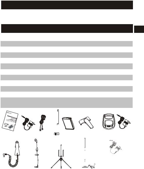
Accessories |
|
EN |
|
|
|
|
1 |
Instruction manual |
1 book |
|
2 |
AC adaptor for base unit (DC 12V/ 800mA) |
1 pc |
|
3 |
Telephone line |
1 pc |
|
4 |
Telescopic antenna for base unit |
1 pc |
|
5 |
Battery pack (Ni-Mh 750mAh) |
1 pc |
|
6 |
Belt clip |
(optional) |
|
7 |
Charger with AC adaptor |
(optional) |
|
8 |
Vehicle charger |
(optional) |
|
9 |
Ear-microphone |
(optional) |
|
10 |
Outdoor antenna with cable for base unit |
(optional) |
|
11 |
Car antenna |
(optional) |
|
|
|
|
|
12 |
Travel charger |
(Attached with |
|
|
|
additional handset) |
|
|
|
|
|
SN- |
258 |
||
Instruction |
Manual |
||
Manual |
|
||
instrucciones |
|||
|
|||
PLUS
EN
ES
RU
(1) |
(2) |
(3) (4) |
(5) |
(6) (optional) |
(7) (optional) |
(12) (Attached with additional handset)
(8) (optional) (9) (optional) (10) (optional) (11) (optional)
1-EN

For Best Performance
Battery Charge
To power the handset, install the battery (p.9) and charge it for about 12 hours before initial use (p.10).
1 |
2 |
3 |
|
H1 VOL |
|
|
|||
4 |
5 |
6 |
|
H2 VOL |
7 |
8 |
9 |
|
|
|
0 |
|
|
H3 RING |
|
|
|
|
|
|
|
|
INT-COM |
MEMO |
CHARGE |
|
|
IN US |
|
|
|
|
E |
|
POWER
W i r e l e s s |
S ol u t i on |
Provider |
Operating Distance/Noise |
EN |
Calls are transmitted between the base unit and the handset using wireless radio waves. For maximum distance and noise free operation, the recommended base unit location is:
Away from electronic appliances such as a TV, personal computer, or another cordless phone. 
At a HIGH and CENTRAL location with no obstructions such as walls.
Raise the base unit antenna and extend fully both the telescopic antenna of base unit and handset.
KEY LOCK |
SCRAMBLER |
IN USE |
BATT.LOW |
 P/ VOL


 FUNC
FUNC 
 REDIAL
 MEMO
MEMO 
FLASH |
ON /OFF |
INT |
|
|
|
1 |
2ABC |
3DEF |
4GHI |
5JKL |
6MNO |
PQ |
8TUV |
W X |
7R S |
9 Y Z |
0Oper
2-EN

Contents
Features . . . . . . . . . . . . . . . . . . . . .5 Location of Controls . . . . . . . . . . . . . . . 6
A. Base Unit . . . . . . . . . . . . . . . . . . . . . . . . . . . . 6
B.Handset . . . . . . . . . . . . . . . . . . . . . . . . . . . . 7
C.Charger (optional) . . . . . . . . . . . . . . . . . . . . . . .7
Installation . . . . . . . . . . . . . . . . . . . . . 8 EN
A. Base Unit . . . . . . . . . . . . . . . . . . . . . . . . . .8
B.Handset . . . . . . . . . . . . . . . . . . . . . . . . . . 9 C. Twin Charger (Optional) . . . . . . . . . . . . . . . . . . . . .9 D. Charging Battery . . . . . . . . . . . . . . . . . . . . . 10
E.Travel Charger (For Additional Handset) . . . . . . . . . . . .10
F.Ear-microphone (Optional) . . . . . . . . . . . . . . . . .11 G. Vehicle charger (Optional) . . . . . . . . . . . . . . . . . . . . 11
H.Outdoor Antenna (Optional). . . . . . . . . . . . . . .12
Basic Operation. . . . . . . . . . . . . . . . 15
A. Turn On/ Off the Handset . . . . . |
. . . . |
. . . . . . 15 |
|||
B. Making Calls . . . . . . . . . . |
. . . . |
. . . . . . 15 |
|||
C. Redial . . . . . . . . . . . . . . |
. . . . . . . . . . . 15 |
||||
D. Automatic Dialling . . . . . . . . . . . . . . . . . . . 16 |
|||||
E. Answering Calls . . . . . . . . . . . |
. . . . . . . . . . . 16 |
||||
F. Intercom . . . . . . . . . . . . |
. . . . |
. . . . . .17 |
|||
G. Intercom during a Call . . . . . . |
. . . . |
. . . . . . 18 |
|||
H. Call Waiting . . . . . . . . . . . |
. . . . |
. . . . . .19 |
|||
I. Walkie-Talkie between handsets . . |
. . . . |
. . |
. |
. |
. 19 |
J. Group Call (Walkie-Talkie Mode) . . |
. . . . |
. . |
. |
. |
. 20 |
3-EN

Advanced Operation. . . . . . . . . . . . . . 23
A. Adjusting Ringer Volume. . . . . . . . . . . . . . . . . 23
B. Adjusting Voice Volume . . . . . . . . . |
. . . . . . . 24 |
C. Selecting Voice Mode . . . . . . . . . . . . |
. . . . . . . . . 25 |
D. Transferring a Call among Handsets. . . . . |
. . . . . . . . 25 |
E.Changing the Channel during a Conversation. . . . . . . .26 F. Display the Battery Status. . . . . . . . . . . . . . . . . . . . . 26
Features Setting. . . . . . . . . . . . . . . . . 27
A. Setting the Base Unit. . . . . . . . . . . . . . . . . . 27 EN
1. Setting Pause duration. . . . . . . . . . . . . . . . . 27
2.Setting Dialling Mode. . . . . . . . . . . . . . . . . . . 27
3.Setting Flash Duration. . . . . . . . . . . . . . . . . . . 27
4.Setting amount of Handsets in the System. . . . . . . . 28
5. Setting Transferring Waiting Time . . . |
. . . . . . . . . . 28 |
||
6. Setting Call-back Waiting Time . . . . |
. . . . . . . . . . 28 |
||
B. Setting the Handset . . . . . . . . . . . |
. . . . . . . . . . 29 |
||
1. |
Change Handset's ID . . . |
. . . . . . . . . . . . . . .29 |
|
2. |
Setting Ring Mode for each |
Handset |
. . . . . . . . . . 29 |
3. Setting Stand-by Time for each Handset . . . . . . . . . 30
Registering Handset for Multi-handset System . .
. . . . . . . . . . . . . . . . . . . . . . . . . . 31
A. Handset Registration . . . . . . . . . . . . . . . . . . . 31 B. De-registering Handset . . . . . . . . . . . . . . . . . . 32
C.Checking the Handset's IID Number. . . . . . . . . . . . . . 32
D.Checking the Parameters . . . . . . . . . . . . . . . . . . 32
Troubleshootings . . . . . . . . . . . . . 33 Specification. . . . . . . . . . . . . . 34 Important Safety Instructions . . . . . . . . . 35
4-EN

Features
*Multi-channel access with auto-scan.
*Multi-handset system (up to 15).
*Multi-base system (up to 4).
*Walkie-talkie between handsets (up to 15 handsets).
*Half-Duplex group call.
*Two-way paging and hands-free intercom.
EN
*10-set memory dial for each handset (20 digits).
*Last number redial.
*Tone/Pulse dialling mode selectable.
*Change channel during conversation.
*Keypad lock function.
*Flash time programmable.
*Ring volume adjustable.
*Voice volume adjustable.
*Music on hold.
*Touch any key answer.
*Handset with power saving circuit.
*Low battery alert and indicator.
*Out of range alert.
*Battery power status display.
*Fast charge.
*Built-in noise cancellation circuit (Compander).
*Built-in voice security and mutation circuit (Scrambler).
*Auto answer and auto hang up.
*Transferring a call among handsets.
*Hands-free kit for handset (optional).
*Separate charger (optional).
*Vibration alert (Vibration version only).
5-EN

Location of Controls
A. Base Unit
Antenna
DC IN jack
TONE/PULSE switch
Speaker
H1/VOL
H2/VOL
/RING H3
|
|
|
|
MO |
|
|
|
|
M/ME |
|
|
|
|
INT-CO |
CH |
AR |
|
|
E |
|
GE |
IN |
US |
|
|
|
|
POWER |
|
|
W i r e l e s s S o l u t i o n Provider |
|||
|
|
|
|
Microphone |
|
|
|
Handset charging slot |
|
Line jack
TEL. jack
H1: Paging handset 1/ voice volume up
H2: Paging handset 2 / voice volume down
H3: Paging handset 3/
Ringer volume adjustable key
INT-COM: Paging all of the handsets / Memo key
CHARGE: CHARGE indicator
POWER: POWER indicator
IN USE: IN USE indicator
6-EN

B. Handset
|
|
|
|
|
Antenna |
Car Antenna |
|
|
|
Indicators |
|
jack |
|
|
|
|
|
|
|
|
|
KEY LOCK: Lock Keypad |
|
|
|
|
|
|
|
Receiver |
|
|
|
IN USE: In use indicator |
|
|
|
|
|
|
BATT. LOW: Low battery |
|
|
|
|
|
indicator |
PTT KEY: Lock Keypad |
|
|
|
|
SCRAMBLER: Scrambler |
/ Push To Talk |
|
|
|
|
indicator |
Scan LED array |
|
|
|
|
|
|
KEY LOCK |
|
|
SCRAMBLER |
|
|
|
IN USE |
BATT.LOW |
|
Function keys |
Operation keys |
|
|
|
|
|
|
|
|
|
P/VOL : Pause/ Ringer |
|
: Talk key/ |
P/ VOL |
|
|
FUNC |
|
REDIAL |
MEMO |
volume/ Speaker |
|||
Flash key |
|
|
|
|
|
|
|
|
|
volume key |
|
|
FLASH |
|
|
INT |
|
: End key/ |
ON /OFF |
|
|||
|
|
|
|||
|
|
|
|
REDIAL : Last number |
|
Power On/Off |
1 |
|
|
3DEF |
|
2ABC |
redial/ Battery |
||||
: Intercom key |
4GHI |
5 |
JKL |
6MNO |
status display key |
|
|
|
|
|
|
|
PQ |
8TUV |
W X |
MEMO : Memory key |
|
|
7R S |
9 Y Z |
|
||
Dialling keys |
|
0Oper |
|
FUNC : Function key |
|
ear-Microphone |
|
|
|
|
DC IN jack |
jack |
|
|
|
|
|
|
|
|
|
|
|
Microphone |
|
|
|
|
|
C. Twin Charger (Optional)
Spare battery slot
Spare battery indicator 


 Power indicator
7-EN
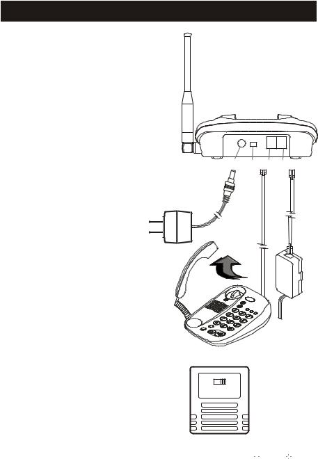
Installation
A. Base Unit
Please set up the base unit according to the following steps (1)~(8).
(1) Install the telescopic antenna of the
(1)
base unit and extend it fully and vertically.
(2) Connect the standard telephone to the TEL. jack.
(3) During installation, pick up the hand |
(6) (5) (2) (4) |
held of the standard telephone to avoid |
|
electric shock caused by an incoming call. |
|
(4) Connect the telephone line
to the LINE jack with the
(8)
local telephone system.
(5) Set the dialling mode to TONE. If you can not dial,
set it to PULSE.
(3)
(6) Please use only the SENAO AC adaptor supplied with
the base unit, and connect the AC adaptor to the DC IN jack.
(7)The AC adaptor is set on 220V. If your
power source is 110V, please switch it to 110V before installing.
(8)Plug the AC adaptor into power outlet.
(7)
110V 220V
AC adaptor
(Output DC 12V

 )
)
8-EN
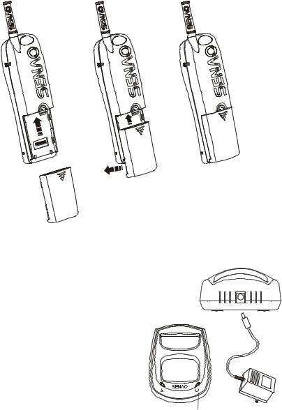
B. Handset
Take the battery from gift box and clip it into the handset.
(1) |
(2) |
(3) |
C. Twin Charger (Optional)
(1) Plug the AC adaptor to the DC IN jack.
(2) Plug the AC adaptor into the electric wall outlet.
(3) The spare battery indicator will becomes flash while is in charge. It becomes green while the battery
is fully charged. It takes around 2 hrs. to fully charge Ni-Mh battery pack.
Spare battery indicator |
|
Power indicator |
|
Note: Please use only the SENAO AC adaptor supplied with this charger.
9-EN
D. Charging Battery Charge
The handset can be charged on the base unit or the charger.
(1)Place the handset on the base unit with facing up. The CHARGE indicator will light up.
(2)Place the handset on the charger with standing up. The scan LED array will run up.
(3)The fast charging will be activated automatically, and the scan LED array runs fast indicating this operation.
(4)The slow charging automatically starts once the fast charging is finished. The scan LED array runs slowly for slow charging.
|
|
KEY LOCK |
|
|
SCRAMBLER |
|
Scan LED array |
|
|
IN USE BATT.LOW |
|
|
|||
|
|
P/ VOL |
|
|
FUNC |
|
|
|
|
REDIAL |
|
MEMO |
|
|
|
|
|
FLASH |
|
|
INT |
|
|
|
|
ON /OFF |
|
|
|
||
|
|
|
|
|
|
|
L |
|
|
1 |
2ABC |
3DEF |
|
1/VO |
|
|
|
|
H |
||||
|
|
4GHI |
|
JKL |
6MNO |
|
L |
|
|
5 |
|
|
|
H2/VO |
|
|
|
PQ |
8TUV |
W X |
|
|
|
|
|
7R S |
9 Y Z |
|
|
||
|
|
|
|
|
|
|
G |
|
|
|
|
|
|
|
/RIN |
|
|
0Oper |
|
|
H3 |
||
|
|
|
|
|
|||
|
|
|
|
|
|
|
MO |
|
|
|
|
|
|
|
M/ME |
|
|
|
|
|
|
|
INT-CO |
CH |
AR |
|
|
|
|
E |
|
|
GE |
|
|
IN |
US |
|
|
|
|
POWER |
|
|
|
||
|
W i r e l e s s S o l u t i o n |
|
|
CHARGE indicator |
|||
|
Provider |
|
|||||
KEY LOCK |
SCRAMBLER |
IN USE |
BATT.LOW |
 P/ VOL


 FUNC
FUNC 
 REDIAL
  MEMO
MEMO 
FLASH |
ON /OFF |
INT |
|
|
|
1 |
2ABC |
3DEF |
4GHI |
5JKL |
6MNO |
PQ |
8TUV |
W X |
7R S |
9 Y Z |
|
|
0Oper |
|
Scan LED array
E. Travel charger (For Additional Handset)
Plug the charger into a wall socket and insert the plug to the DC IN jack of your handset. The charging times
is approximately 5 hours. Check the charging status on the
LED array. The operation of handset could be executed during the charging process.
10-EN

F. Ear-Microphone (Optional)
You can answer and end calls by pressing the button on the microphone part of the ear-microphone. It also could be used as the Walkie-Talkie function. You can press button to talk, then release it to listen.
Answer / End / Push to Talk
Key
Note: To end calls, please keep pressing button for more than 2 sec.
G. Vehicle charger (Optional)
The vehicle charger's ensures your phone is ready for use wherever you travel. This small charger's functional design fits most car lights and interiors. The charging time is about 5 hours, and you can use your phone freely during charging. A green light indicates that is ready for charging. Check the charging status on the phone display. The input voltage can be 12 or 24 V DC, negative grounding.
Avoid prolonged charging when the car engine is not running, this may cause the battery of your car to drain. Note also that in some cars the cigarette lighter plug is not provided with electricity if the ignition is switched off. Verify that green LED light is on.

 Power indicator
11-EN
 Loading...