

Page 1

Secure Terminal Server
STS Series
User Guide
Version 1.3.3
2005-11-08
1
Page 2

Copyright Information
Copyright 1998-2005, Sena Technologies, Inc. All rights reserved.
Sena Technologies reserves the right to make any changes and improvements to its product without
providing prior notice.
Trademark Information
HelloDevice™ is a trademark of Sena Technologies, Inc.
Windows® is a registered trademark of Microsoft Corporation.
Ethernet® is aregistered trademark of XEROX Corporation.
Notice to Users
Proper back-up systems and necessary safety devices should be utilized to protect against injury,
death or property damage due to system failure. Such protection is the responsibility of the user.
This device is not approved for use as a life-support or medical system.
Any changes or modifications made to this device without the explicit approval or consent of Sena
Technologies will void Sena Technologies of any liability or responsibility of injury or loss caused by
any malfunction.
Technical Support
Sena Technologies, Inc.
210 Yangjae-dong, Seocho-gu
Seoul 137-130, Korea
Tel: (+82-2) 573-5422
Fax: (+82-2) 573-7710
E-Mail: [email protected]
Website: http://www.sena.com
2
Page 3

Revision history
Revision Date Name Description
V1.0.2 2003-12-3 O.J. Jung Initial Release
V1.1.0 2004-01-12 O.J. Jung Revision with release of version 1.1.0
V1.1.1 2004-01-30 O.J. Jung Typographical errorsare fixed
V1.2.0 2004-06-11 O.J. Jung Revision with release of version 1.2.0
V1.3.0 2004-10-11 O.J. Jung Revision with release of version 1.3.0
V1.3.1 2004-10-15 O.J. Jung Added Appendix 6
V1.3.2 2005-05-18 O.J. Jung
V1.3.3 2005-11-08 Hunn Lee Temperature and Humidity update
Appendix 7 is added, PC Card List is updated,
The description about DSR behavior is corrected.
Typographical errorsare fixed.
3
Page 4

Contents
1. Introduction 7
1.1. Overview....................... .... ......... ..... .... .......... .... ..... ......... .... ..... ......... ..... .... ......... ......................7
1.2. Package Check List...................................................................................................................8
1.3. Product Specification.................................................................................................................9
1.4. Terminologies and acronyms...................................................................................................10
2. Getting Started 12
2.1. Panel Layout...........................................................................................................................12
2.1.1. STS800 Panel Layout.....................................................................................................12
2.1.2. STS1600 Panel Layout...................................................................................................13
2.2. Connecting the Hardware .. ..... .... ..... ......... .... ..... ......... ..... .... ......... ..... ..... .... ......... ..... .... ...........13
2.2.1. Connecting the power.....................................................................................................13
2.2.2. Connecting to the network..............................................................................................14
2.2.3. Connecting to the device ............................................................... .................................15
2.2.4. Accessing the System Console.......................................................................................15
2.2.5. Using the System console ........................................................ ......................................16
2.2.6. Using Remote console....................................................................................................17
2.3. Accessing the Web Browser Management Interface ......................................................... ......18
3. Network Configuration 21
3.1. IP Configuration...................................................................................... .... ..... .... ....................21
3.1.1. Using a Static IP Address................................................................................................22
3.1.2. Using DHCP ...................................................................................................................23
3.1.3. Using PPPoE..................................................................................................................24
3.2. SNMP Configurations................................................................................. .............................25
3.2.1. MIB-II System objects Configuration...............................................................................26
3.2.2. Access Control Configuration..........................................................................................27
3.2.3. Trap Receiver Configuration...........................................................................................27
3.2.4. Management using SNMP..............................................................................................27
3.3. Dynamic DNS Configuration............ ........................................................................................28
3.4. SMTP Configuration................................................................................................................29
3.5. IP Filtering......................................................................................... ..... ......... .... ....................30
3.6. SYSLOG server configuration .................................................................................................32
3.7. NFS server configuration................................................................... ..... .... ......... ..... ..... ..........32
3.8. Ethernet configuration............ ......................................................................... ........................33
3.9. Web server configuration.......................... ......... ..... .... ......... ..... ..... .... ......... ..... .... .......... ..........34
3.10. TCP service configuration......................................................................................................34
4. Serial Port Configuration 36
4
Page 5

4.1. Overview....................... .... ......... ..... .... .......... .... ..... ......... .... ..... ......... ..... .... ......... ....................36
4.2. Individual Port Configuration .................... ..... .... ..... ......... .... ..... ..... ......... .... ..... ......... ..... ..........39
4.2.1. Port Enable/Disable........................................................................................................40
4.2.2. Port Title.........................................................................................................................40
4.2.3. Apply All Port Settings.....................................................................................................40
4.2.4. Host Mode Configuration........................................................................ ........................41
4.2.5. Remote host configuration................................. .............................................................49
4.2.6. Port IP filtering configuration...........................................................................................50
4.2.7. Cryptography configuration.............................................................................................51
4.2.8. Serial port parameters ....................................................................................................56
4.2.9. Modem configuration ................................................................ ......................................59
4.2.10. Port Logging .................................................................. ..... .... ..... ......... .... ..... ...............60
4.2.11. Port event handling configurations................................................................................62
4.3. All Port Configurations.............................................................................................................66
5. PC Card Configuration 68
5.1. LAN Card Configuration ......................................... ......... .... ..... ......... ..... .... ......... ..... .... ...........69
5.2. Wireless LAN Card Configuration............................................................................................70
5.3. Serial Modem Card Configuration...........................................................................................72
5.4. ATA/IDE Fixed Disk Card Configuration.................................................. .... ......... ..... .... ......... ..72
6. System Administration 74
6.1. System Status .........................................................................................................................74
6.2. System Logging.......................................................................................................................74
6.3. User Logged on List................................................................................................................76
6.4. Change Password............. ......... ..... .... .......... .... ......... ..... .... .......... .... ..... ......... .... ..... ...............77
6.5. Device Name Configuration............. .... .......... .... ..... .... ......... ..... ..... ......... .... ..... .... .......... .... ......77
6.6. Date and Time Settings....................................................................................... ....................77
6.7. Configuration management........................... ......... .... ..... .... .......... .... ..... .... ......... ..... ..... .... ......78
6.8. Firmware Upgrade............. ..... ......... .... .......... .... ..... ......... .... ..... ......... ..... .... ......... ..... .... ...........80
6.9. User File Uploading.................................................................................................................83
7. System Statistics 85
7.1. Network Interfaces Statistics............................................................................... ..... ...............85
7.2. Serial Ports Statistics...............................................................................................................85
7.3. IP Statistics................................. ......... ..... .... .......... .... ..... ......... .... ..... ......... ..... .... ....................86
7.4. ICMP Statistics....................... .... ......... ..... .... .......... .... ..... ......... .... ..... ......... ..... .... ....................88
7.5. TCP Statistics..........................................................................................................................90
7.6. UDP Statistics.................................................................. .... ......... ..... ..... ......... .... ..... .............. .92
8. CLI guide 93
8.1. Introduction ................................................................ ......... ..... ..... ......... .... ..... .... ....................93
5
Page 6

8.2. Flash partition............................................................. ..... ......... .... ..... ......... ..... .... ....................93
8.3. Supported Linux Utilities............................... ...........................................................................94
8.3.1. Shell & shell utilities:................... ....................................................................................94
8.3.2. File and disk utils:...........................................................................................................94
8.3.3. System utilities:...............................................................................................................94
8.3.4. Network utilities:..............................................................................................................94
8.4. Accessing CLI as root or system administrator......................... ...............................................94
8.5. Examples ................................................................................................................................94
8.5.1. Disabling the Telnet Port of the Unit................... .............................................................94
8.5.2. Periodical program execution..........................................................................................96
Appendix 1. Connections 97
A 1.1. Etherne t Pin ou ts..................................................................................................................97
A 1.2. Console and Serial port pin-outs..........................................................................................97
A 1.3. Ethernet Wiring Diagram......................................................................................................98
A 1.4. RS232 Serial Wiring Diagram ..............................................................................................98
Appendix 2. PC card supported by STS 100
Appendix 3. STS Configuration files 102
A 3.1. System.cnf .............................................................. ...........................................................102
A 3.2. Redirect.cnf........................................................................................................................104
Appendix 4. Well-known port numbers 108
Appendix 5. Guide to the Bootloader menu program 109
A 5.1. Overview............................................................................................................................109
A 5.2. Main menu .........................................................................................................................109
A 5.3. RTC configuration menu ....................................................................................................109
A 5.4. Hardware test menu........................................................................................................... 110
A 5.5. Firmware upgrade menu.............................................................................. ......................114
Appendix 6. Using STS Series with Serial/IP 116
A 6.1. STS Se ries vs . Serial/IP options......................................................................................... 116
A 6.2. Connection example - Telnet and SSLv3 encryption ..........................................................117
Appendix 7. How to make a certificate for SSL encryption 121
A 7.1. Install the OpenSSL package.............................................................................................121
A 7.2. Make root CA (for Self-signed)...........................................................................................121
A 7.3. Making a certificate request ...............................................................................................123
A 7.4. Signing a certificate request...............................................................................................123
A 7.5. Making certificate for STS..................................................................................................124
6
Page 7

1. Introduction
1.1. Overview
The STS Series is a secure terminal server (or device server) that makes your legacy serial devices
manageable by industry-standard Ethernet network. Based on open network protocols such as TCP/IP
and UDP, it gives you ultimate flexibility to your serial devices. With PPPoE (PPP-over-Ethernet)
connection feature of the STS Series, the RS232 serial devices could be managed over D SL-based
broadband network.
With the rich broadband network connectivity protocols such as DHCP, PPPoE and Dynamic
DNS, you could easily manage the legacy serial devices over broadband Internet by using DSL or
cable modem connection. The built-in Dynamic DNS protocol of the STS Series enables you to access
the serial devices with their domain names.
The STS Series also provides you with full-featured system management functionality of system
status display, firmware upgrade, remote reset and system log display by using various ways such as
telnet, serial console port or web.
You could easily configure and administrate the STS Series, with the full-featured management
functions of status monitor, remote reset, error log monitor and firmware upgrade by using Telnet and
serial console port under the password protection support.
For critical applications of secure data communication, the STS Series supports SSLv2, SSLv3
and TLSv1 for data encryption. In addition, IP address filtering function is provided for protecting
unintentional data streams to be transmitted to the STS Series.
Typical application areas of the STS Series are:
- Industrial automation
- Network management
- Retail/Point of sale
- Remote metering
- Remote display
- Building automation
- Security/Access control systems
- General data acquisition application
- Medical application
The STS Series gives you ideal remote management capability of control, monitoring, diagnosis and
data gathering over RS232 serial devices.
Please note that this manual assumes user knowledge of Internetworking protocols and
serial comm un ications.
7
Page 8

1.2. Package Check List
- STS Series external box
- External 110V or 230V power supply or power cord
- CAT5 cable
- Console cable kit
- Quick Start Guide
- CD-ROM, including the Serial/IP Com Port Redirector, HelloDevice-IDE, HelloDevice Manager
and manuals
8
Page 9

1.3. Product Specification
STS800 STS1600
Serial Interface
Flow Control:
Hardware RTS/CTS, Software Xon/Xoff
Signals:
RS232 Rx, Tx, RTS, CTS, DTR, DSR, DCD, GND
Modem controls: DTR/DSR and RTS/CTS
Network Interface
Protocols
PCMCIA Supports one of the following PC cards:
Security
Modem emulation Full support for AT commands
Management
Diagnostic LED Power
Environmental
Power 5VDC, 1.5A @ 5VDC 110 ~ 240VAC
10/100 Base-Tx Ethernet with RJ45 Ethernet connector
Supports static and dynamic IP address
- ARP, IP/ICMP, TCP, UDP, Telnet, SSH v1 & v2,
- SSL v2 & v3, TLS v1
- DNS, Dynamic DNS, HTTP, HTTPS,
- SMTP with/without Authentication, pop-before SMTP,
- DHCP client, NTP, PPPoE, SNMP v1 & v2
ATA flash memory card
802.11b Wireless LAN card
10/100 Base-TX LAN Card
Modem card
User ID & Password
HTTPS
Secure terminal interface: SSH
Data Encryption: SSLv2/v3, TLS v1, 3DES and RC4
IP address filtering
SCP
Web, Telnet or Serial console port or HelloDevice Manager
O/S support: Windows 98/ME/NT/2000/XP
System log
Automatic email delivery of error log
System statistics
Full-featuredsystem status display
Firmware
Stored in Flash memory and upgradeable via serial console, telnet or web
Ready
10/100 Base Link, Act
Serial InUse/Rx/ Tx for each port
PC Card
Operating temperature: 0’C to 50’C
Storage temperature: –20’C to 66’C
Humidity: 90% Non-condensing
245 x 153 x 30 (mm) 432 x 193 x 44.5Dimension
L x W x H (mm)
Weight (kg) 1.5 2.8
Certification FCC(A), CE(A), MIC
DIN-rail mount option 19 in. rack mountable
8-port 16-port
Serial speeds 75bps to 230Kbps
RJ45 connector
9
Page 10

Warranty 5-year limited warranty
1.4. Terminologies and acronyms
This section will define commonly used terms in this manual. These terms are related to
Internetworking, and defined in regards to their use with STS Series.
MAC address
On a local area network or other network, the MAC (Media Access Control) address is the computer's
unique hardware number. (On an Ethernet LAN,it is the same as theEthernet address.)
It is a unique 12-digit hardware number, which is composed of 6-digit OUI (Organization Unique
Identifier) number and 6-digit hardware identifier number. The STS Series has the following MAC
address template: 00-01-95-xx-xx-xx. The MAC address can be found on the bottom of the original
package.
Host
A user’s computer connected to the network
Internet protocol specifications define "host" as any computer that has full two-way access to
other computers on the Internet. A host will have a specific "local” or “host number" that, together with
the network number, forms its unique IP address.
Session
A series of interactions between two communication end points that occur during the span of a single
connection
Typically, one end point requests a connection with another specified end point. If that end point
replies,agreeing to the connection, the end points take turns exchanging commands and data ("talking
to each other"). The session begins when the connection is established at both ends and terminates
when the connection is ended.
Client/Server
Client/server describes the relationship between two computer programs in which one program, the
client, makes a service request from another program, the server, which fulfills the request.
A server is a computer program that provides services to other computer programs on one or
many computers. The client is the requesting program or user in a client/server relationship. For
example, the user of a Web browser is effectively making client requests for pages from servers all
over the Web. The browser itself is a client in its relationship with the computer that is getting and
returning the requested HTML file. The computer handling the request and sending back the HTML file
is a server.
10
Page 11

Table 1-1 Acronym Table
ISP Internet Service Provider
PC
NIC
MAC Media Access Control
LAN Local Area Network
UTP
ADSL Asymmetric Digital Subscriber Line
ARP Address Resolution Protocol
IP
ICMP Internet Control Message Protocol
UDP User Datagram Protocol
TCP
DHCP Dynamic Host Configuration Protocol
SMTP Simple Mail Transfer Protoco l
FTP File Transfer Protocol
PPP Point-To-Point Protocol
PPPoE Point-To-Point Protocol over Ethernet
HTTP HyperText Transfer Protocol
DNS
DDNS Dynamic Domain Name Service
SNMP Simpl e Network Management Protocol
RADIUS
SSH Secure Shell
NTP Network Time Protocol
UART
Bps Bits per second (baud rate)
DCE Data Communications Equipment
DTE Data Terminal Equipment
CTS
DSR Data Set Ready
DTR Data Terminal Ready
RTS
DCD Data Carrier Detect
Personal Computer
Network Interface Card
Unshielded Twisted Pair
Internet Protocol
Transmission Control Protocol
Domain Name Service
Remote Access for Dial-In User Service
Universal Asynchronous Receiver/Transmitter
Clear to Send
Request To Send
11
Page 12
2. Getting Started
This chapter describes how to set up and configure the STS Series.
- 2.1 Panel Layout explains the layout of the panel and LED indicators.
- 2.2 Connecting the Hardware describes how to connect the power, the network, and the
equipment to the STS Series.
- 2.3 Accessing the Web Browser Management Interface describes how to access the console
port using a serial console or a Telnet or Web menu from remote location.
The following items are required to get started.
- One power cable (included in the package)
- Console and Ethernet cables (included in the package)
- Cable kit (included in the pac kage)
- One PC with Network Interface Card (hereafter, NIC) and/or one RS232 serial port.
2.1. Panel Layout
2.1.1. STS800 Panel Layout
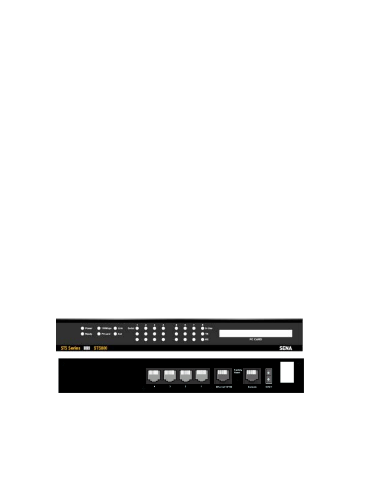
The STS800 has three groups of LE D indicator lamps to display the status, as shown in Figure 2-1
and Figure 2-2 (i.e. System, Ethernet and Serial ports). The first three lamps on the left side indicate
Power, Ready and PC Card interface. The next three lamps are for Ethernet 100Mbps, Link and Act.
Next lamps indicate InUse, Receive and Transmit of the serial ports.
Table 2-1 describes the function of each LED indicator lamp. The rear panel shows the serial ports
with RJ45 connector, Ethernet port, the STS800 console port and the power socket.
Figure 2-1 The panel layout of the STS800
Table 2-1 LED indicator lamps of the STS Series
12
Page 13
Lamps Function
System
Ethernet
Serial port
Power Turned on if power is supplied
Ready Turned on if system is ready to run
PC card
100Mbps Turned on if 100Base-TX connection is detected
LINK Turned on if connected to Ethernet network
Act
InUse
Rx/Tx Blink whenever there is any incoming or outgoing data strea m through the
Turned on if a PCMCIA device is running
Blink whenever there is any activities such as incoming or outgoing packets
through the STS Series Ethernet port
Turned on if the serial port is in use (Port buffering enabled or port access in
use)
serial port of the STS Series
2.1.2. STS1600 Panel Lay out
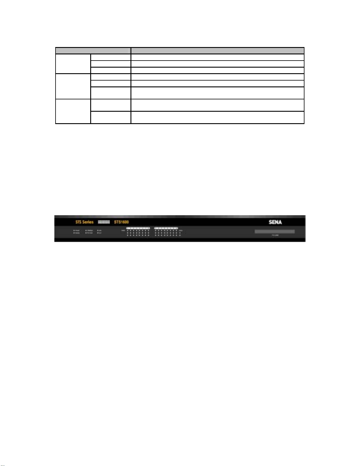
The STS1600 has three groups of LED indicator lamps to display the status, as shown in Figure 2-2
(i.e. System, Ethernet and Serial ports). The first three lamps on the left side indicate Power, Ready
and PCMCIA interface. The next three lamps are for Ethernet 100Mbps, Link and Act. Next lamps
indicate InUse, Receive and Transmit of the serial ports.
Table 2-1 describes the function of each LED ind icator lamp.
Figure 2-2 The panel layout of the STS1600
2.2. Connecting the Hardware
This section describes how to connect the STS Series to the equipment for initial testing.
- Connect a power source to the STS Series
- Connect the STS Series to an Ethernet hub or switch
- Connect the device
2.2.1. Connecting the power
Connect the power cable to the STS Series. If the power is properly supplied, the [Power] lamp will
light up green.
13
Page 14
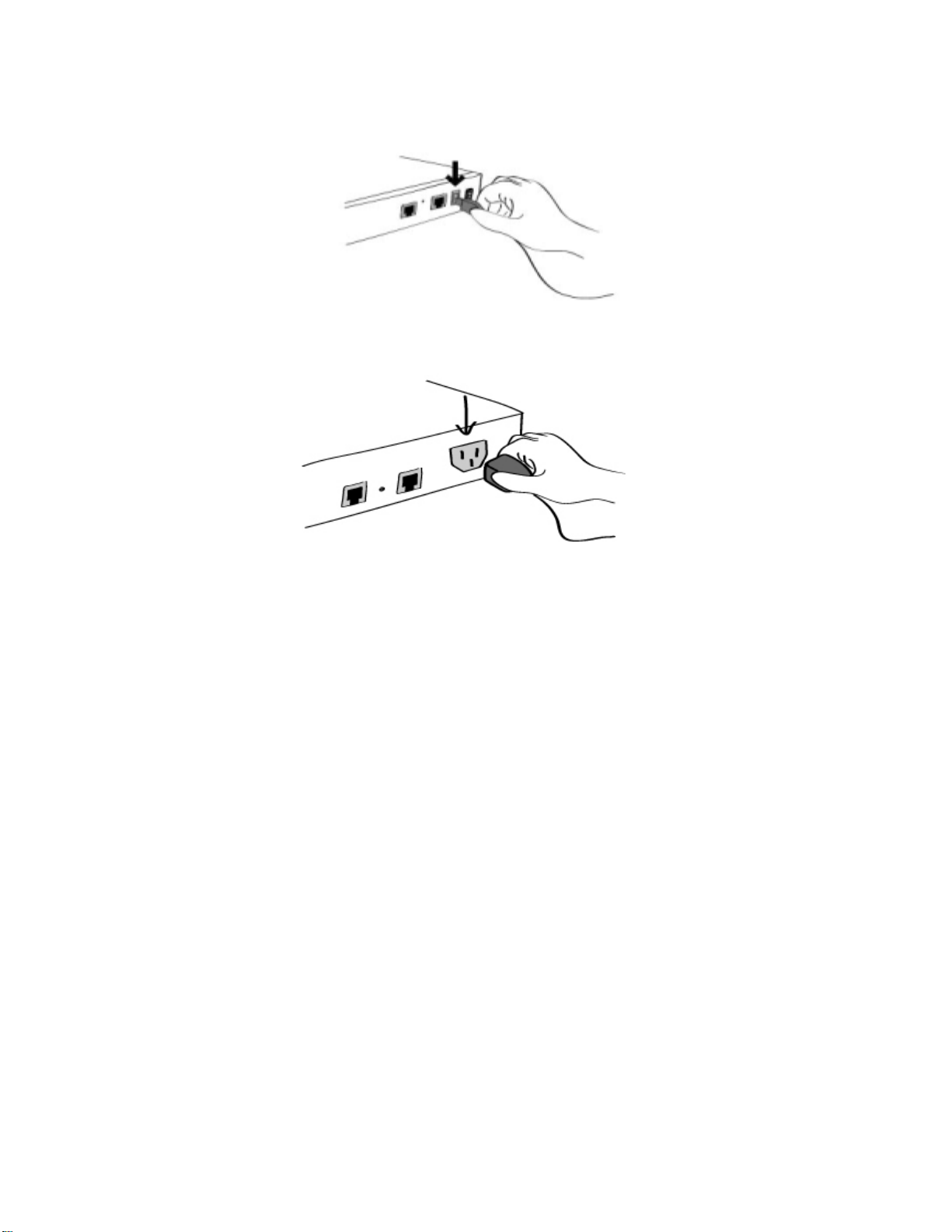
Figure 2-3 Connecting the po wer to the STS800
Figure 2-4 Connecting the power to the STS1600
2.2.2. Connecting to the network
Plug one end of the Ethernet cable to the STS Series Ethernet port. The other end of the Ethernet
cable should be connected to a network port. If the cable is properly connected, the STS Series will
have a valid connection to the Ethernet network. This will be indicated by:
The [Link] lamp will light up green.
The [Act] lamp will blink to indicate incoming/outgoing Ethernet packets
The [100Mbps] lamp will light up green if the STS Series is connected to 100Base-TX network
The [100Mbps] lamp will not turn on if the current network connection is 10Base-T.
14
Page 15
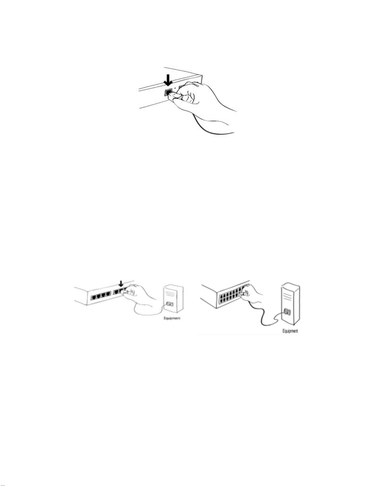
Figure 2-5 Connecting a network cable to the STS800/1600
2.2.3. Con necting to the device
Connect the console cable to the STS Series serial port. To connect to the console port of the device,
the user needs to consider the type of console port provided by the device itself. In the STS Series
cable kit package, plug-in adapters are provided for the easier connectivity to the user’s devices.
Please refer to the Appendix 1 Connections for details.
Figure 2-6 Connecting a equipment to the STS800(Left) / STS1600(Right)
2.2.4. Accessing the System Consol e
There are several ways to access the STS Series. These methods are dependent on whether the user
is located at a local site or a remote site, or whether s/he requires a menu-driven interface, graphic
menu system or CLI (Command Line Inte rface).
15
Page 16
System console:
Local users can connect directly to the system console port of the STS Series using the
console/Ethernet cable with the corresponding adapter.
Remote console:
Remote users who require a menu-driven interface can utilize Telnet (port 23) connections to the
STS Series using terminal emulator.
Web:
Remote users who want to use a web browser to configure the STS Series can connect to the
STS Series using conventional web browsers, such as Internet Explorer or Netscape Navigator.
The above methods require the user authentication by the STS Series system.
2.2.5. Using the System console
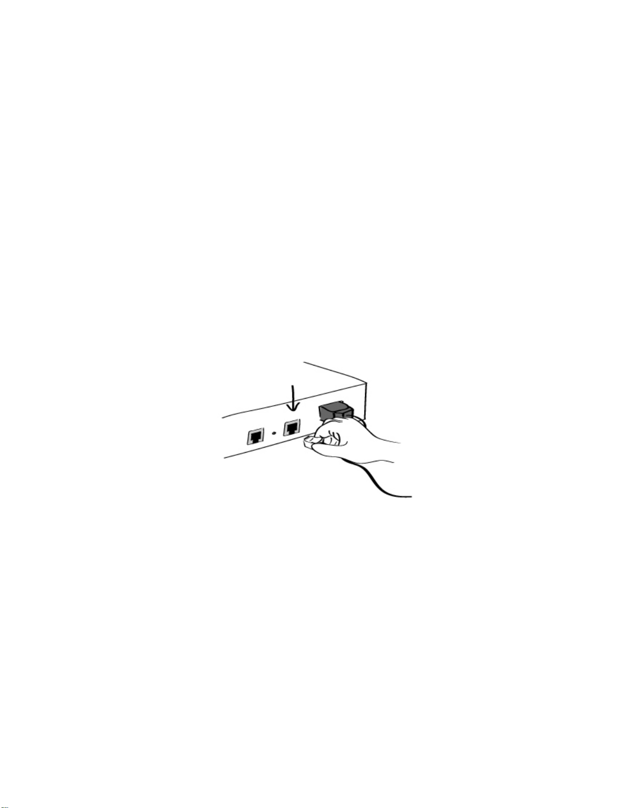
1) Connect one end of the console/Ethernet cable to the console port on the STS Series.
Figure 2-7 Connecting a system console cable to the STS Series
2) Connect to the user’s computer with the RJ45-DB9 female adapter.
3) Connect the other end of the cable to the serial port of the user’s computer.
4) Run a terminal emulator program (i.e. HyperTerminal). Set up the serial configuration
parameters of the terminal emulation program as follows:
9600 Baud rate
Data bits 8
Parity None
Stop bits 1
No flow control
5) Press the [ENTER] key.
6) Enter your user name and password to log into the STS Series. The factory default user
16
Page 17

settings are as follows.
Login: root Password: root
Login: admin Password: admin
192.168.161.5 login: root
Password:****
[email protected]:~#
7) Upon authentication, the CLI are initially provided for configuration. For details on the CLI,
refer to the chapter 8 CLI guide.
8) “ss.edit” command will allow you to enter the text-menu driven interface and the menu screen
in Figure 2-8 is displayed.
[email protected]:~#ss.edit
----------------------------------------------------------------------------- Welcome to STS-800 configuration page
Current time: 08/22/2003 21:52:36 F/W REV.: v1.0.1
Serial No.: STS800438349-42944 MAC address: 00-01-95-04-19-5a
IP mode: DHCP IP address: 192.168.14.7
----------------------------------------------------------------------------- Select menu:
1. Network configuration
2. Serial port configuration
3. PC Card configuration
4. System administration
5. Save changes
6. Exit without saving
7. Exit and apply changes
8. Exit and reboot
<Enter> Refresh
----->
Figure 2-8 The main menu screen (STS800)
From the main menu screen, the user may select the menu item for the configuration of the STS
Series parameters by typing the menu number and pressing the [ENTER] key. In the submenu screen,
users can configure the required parameters guided by online comments. All the parameters are
stored into the non-volatile memory space of the STS Series, and it will not be stored until users select
menu ”5.Save changes”. All the configuration change will be effective after selecting the menu “7. Exit
and apply changes” or “8. Exit and reboot”.
2.2.6. Using Remote console
The IP address of the STS Series must be known before users can access the STS Series using the
Remote console (see chapter 3 Network Configuration for details). The default IP address of STS
17
Page 18
Series is
Filtering for details).
192.168.161.5
The Remote co nsole access functi on can be disabled in th e remote host access op tion (3.5 IP
The following instructions will assist in setting up the Remote Console functionality:
1) Run either a Telnet program or a program that supports Telnet functions (i.e. TeraTerm-Pro
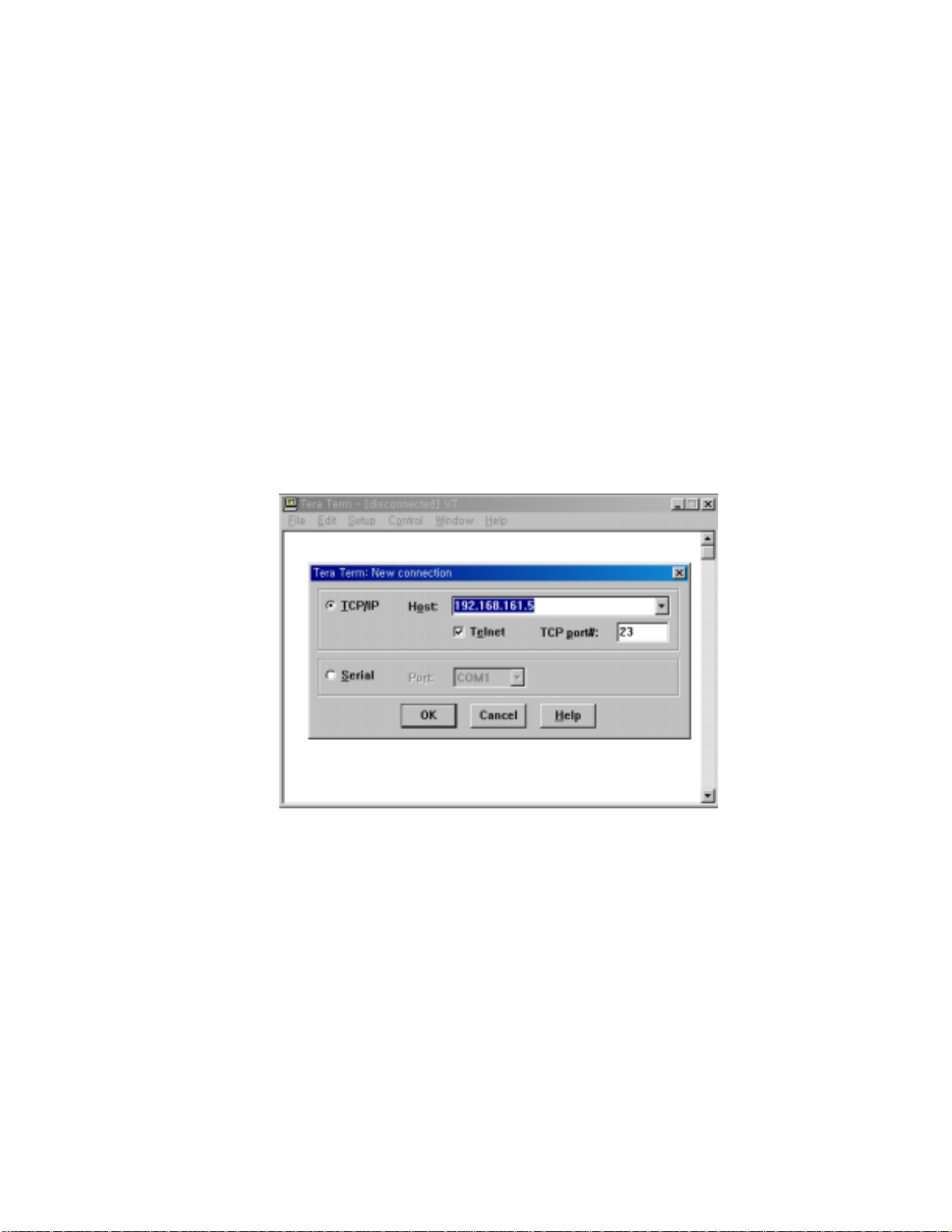
or HyperTerminal). The target IP address and the port number must match the STS Series. If
required, specify the port number as 23. Type the following command in the command line
interface of user’s computer.
telnet 192.168.161.5
Or run a Telnet program with the following parameters:
.
Figure 2-9 Telnet program set up example (TeraTerm Pro)
2) The user must log into the STS Series. Type the user name and password. A factory default
setting of the user name and password are both root for the system root and admin for the
system administrator.
3) Upon authentication by the STS Series, the CLI prompts or text menu screens are shown.
2.3. Accessing the Web Browser Management Interface
The STS Series supports both HTTP and HTTPS (HTTP over SSL) protocols. The STS Series also
provides has its own Web management pages. To access the STS Series Web management page,
enter the IP address or resolvable hostname of the STS Series into the web browser’s URL/Location
18
Page 19
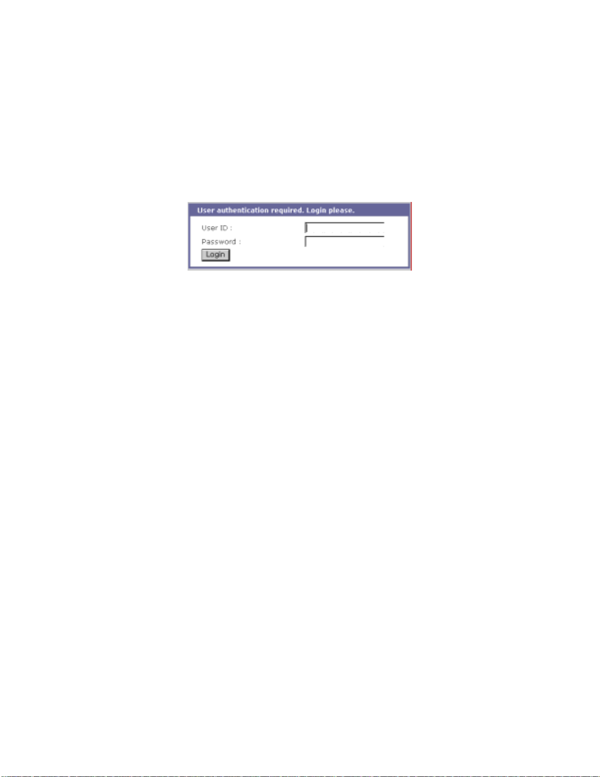
field. This will direct the user to the STS Series login screen. The user must authenticate themselves
by logging into they system with a correct user name and password. The factory default settings are:
Login: root Password: root
Login: admin Password: admin
Note: Before access ing the STS Series Web management page, the user must check the IP address
(or resolvable Hostname) of the STS Series and Subnet mask settings.
Figure 2-10 Login screen of the STS Series web management
Figure 2-10 shows Login screen of the STS Series web management. After login, user can see the
configuration homepage of the STS Series Web management interface shown Figur e 2- 11.
Figure 2-11 shows t he conf igurat ion home page of t he STS Ser ies Web m anageme nt inter face. A
menu bar is provided on the left side of the screen. The menu bar includes the uppermost
configuration menu groups. Selecting an item on the menu bar opens a tree view of all the submenus
available under each grouping. Selecting a submenu item will allow the user to modify parameter
settings for that item. Every page will allow the user to [Save to flash], [Save & apply] or [Cancel] their
actions. After changing the configuration parameter values, the users must select [Save to flash] to
save the changed parameter values to the non-volatile memory. To apply all changes made, the user
must select [Apply Changes]. This option is available on the bottom of the menu bar. Only when the
user selects [Apply changes] will the new parameter values be applied to the STS Series configuration.
The user also can select [Save & apply] to save parameters and apply changes in one step.
If the user does not want to save the new parameter values, the user must opt to [Cancel]. All
changes made will be lost and the previous values restored.
19
Page 20
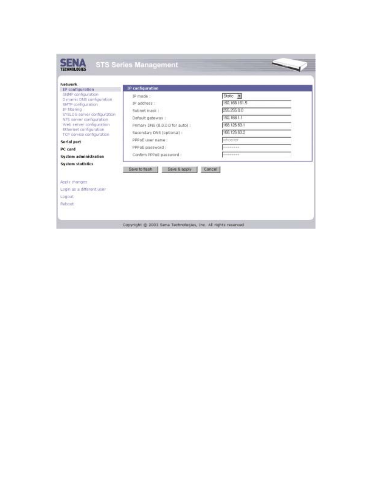
Figure 2-11 The STS Series web management screen
20
Page 21

3. Network Configuration
3.1. IP Configuration
The STS Series requires a valid IP address to operate within the user’s network environment. If the
IP address is not readily available, contact the system administrator to obtain a valid IP address for the
STS Series. Please note that the STS Series requires a unique IP address to connect to the user’s
network.
The users may choose one of three Internet protocols in setting up the STS Series IP address:
i.e.,
• Static IP
•
• PPPoE
The STS Series is initially defaulted to STATIC mode, with a static IP address of 192.168.161.5. Table
3-1 shows the configuration parameters for all three IP configurations. Figure 3-1 shows the actual
web-based GUI to change the user’s IP configuration.
(Dynamic Host Configuration Protocol)
DHCP
(Point-to-Point Protocol ov er Ethernet)
Table 3-1 IP configur at i o n Parameters
Static IP
DHCP
PPPoE
IP address
Subnet mask
Default gateway
Primary DNS/ Secondary DNS
Primary DNS/ Secondary DNS (Optional)
PPPoE Username
PPPoE Password
Primary DNS/ Secondary DNS (Optional)
21
Page 22
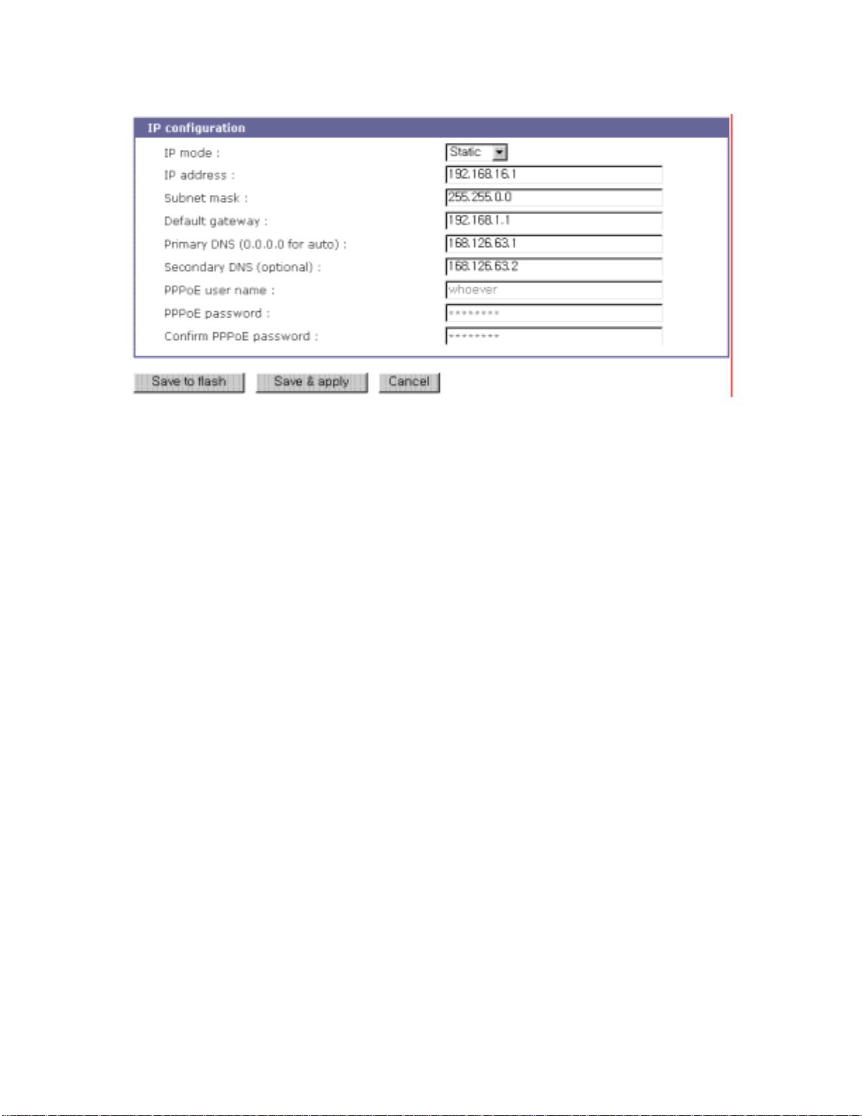
Figure 3-1 IP Configuration
3.1.1. Using a Static IP Address
When using a
associated with the IP address of the STS Series. These include the IP address, the network subnet
mask, the gateway computer and the domain name server computers. This section will look at each of
these in more detail.
Note: The STS Series will attempt to locate all this information every time it is turned on. .
Static IP
address, the user must manually specify all the configuration parameters
IP address
A Static IP address acts as a “static” or permanent identification number. This number is assigned to
a computer to act as its location address on the network. Computers use these IP addresses to
identify and talk to each other on a network. Therefore, it is imperative that the selected IP address be
both unique and valid in a network environment.
Note: 192.168.1.x will never be assigned by and ISP (Internet Service Provider). IP addresses using
this form are considered private. Actual applications of the STS Series may require access to public
network, such as the Internet. If so, a valid public IP address must be assigned to the user’s computer.
A public IP address is usually purchased or leased from a local ISP.
Subnet mask
A subnet represents all the network hosts in one geographic location, such as a building or local area
network (LAN ). The STS Series will us e the subnet mas k setting t o verify the origi n of all packets . If
the desired TCP/IP host specified in the packet is in the same geographic location (on the local
22
Page 23

network segment) as defined by the subnet mask, the STS Series will establish a direct connection. If
the desired TCP/IP host specified in the packet is not identified as belonging on the local network
segment, a connection is established through the given default gateway.
Default gateway
A gateway is a network point that acts as a portal to another network. This point is usually the
computer or computers that c ontrol traffic withi n a network or a loc al ISP (Internet s ervice provider).
The STS Series uses the IP address of the default gateway computer to communicate with hosts
outside the local network environment. Refer to the network administrator for a valid gateway IP
address.
Primary and Secondary DNS
The DNS (Domain Name System) server is used to locate and translate the correct IP address for a
requested web site address. A domain name is the web address (i.e. www.yahoo.com) and is
usually easier to remember. The DNS server is the host that can translate such text-based domain
names into the numeric IP addresses for a TCP/IP connection.
The IP address of the DNS server must be able to access the host site with the provided domain
name. The STS Series provides the ability to configure the required IP addresses of both the Primary
and Secondary DNS servers addresses. (The secondary DNS server is specified for use when the
primary DNS server is unavailable.)
3.1.2. Using DHCP
Dynamic Host Configuration Protocol (DHCP) is a communications protocol that lets network
administrators manage and automate the assignment of IP addresses centrally in an organization's
network. DHCP allows the network administrator the ability to supervise and distribute IP addresses
from a central point and automatically send a new IP address when a computer is plugged into a
different network location.
When in static IP mode, the IP address must be entered manually at each computer. If a
computer is moved to another network location, a new IP address must be assigned. DHCP allows all
the parameters, including the IP address, subnet mask, gateway and DNS servers to be automatically
configured when the IP address is assigned. DHCP uses a “lease” concept in assigning IP addresses
to a computer. It limits the amount of time a given IP address will be valid for a computer. All the
parameters required to assign an IP address are automatically configured on the DHCP server side,
and each DHCP client computer receives this information when the IP address is provided at its bootup.
Each time a computer is reset, the STS Series broadcasts a DHCP request over the network. The
reply generated by the DHCP server contains the IP address, as well as the subnet mask, gateway
23
Page 24

address, DNS servers and the “lease” time. The STS Series immediately places this information in its
memory. Once the “le ase” expires, the STS Series will request a renewal of the “lease” time from the
DHCP server. If the DHCP server approves the request for renewal, the STS Series can continue to
work with the current IP address. If the DHCP server denies the request for renewal, the STS Series
will start the procedure to request a new IP address from the DHCP server.
Note: While in DHCP mode, all network-related parameters for the STS Series are to be configured
automatically, including the DNS servers. If the DNS server is not automatically configured, the user
may manually configure the settings by entering the primary and secondary DNS IP addresses. To
force an automatic configuration of the DNS address, set the primary and secondary DNS IP
addresses to 0.0.0.0 (recommended).
A DHCP sever assigns IP addresses dynamically from an IP address pool, which is managed by the
network administrator. This means that the DHCP client, i.e. the STS Series, receives a different IP
address each time it boots up. The IP address should be reserved on the DHCP server side to assure
that the user always knows the newly assigned STS Series address. In order to reserve the IP
address in the DH CP network, th e administr ator needs t he MAC address of the STS Series found on
the label sticker at the bottom of the STS Series.
3.1.3. Usin g PPPoE
PPPoE (Point-to-Point Protocol over Ethernet) is a specification for connecting multiple computer
users on an Ethernet LAN (local area network) to a remote site through a modem or similar device.
PPPoE can be used to multiple users the ability to share ADSL, cable modem, or wireless connection
to the Internet.
To use the STS Series in PPPoE mode, users require a PPPoE account and the necessary
equipment for PPPoE access (i.e. an ADSL modem). Since the STS Series provides a PPPoE
protocol, it can access the remote host on the Internet over an ADSL connection. The user will have to
set up the user name and password of the PPPoE account for the STS Series.
The STS Series negotiates the PPPoE connection with the PPPoE server whenever it boots up.
During the negotiation, the STS Series receives the information required for an Internet connection,
such as the IP address, gateway, subnet mask and DNS servers. If the connection is established, the
STS Series will maintain the connection for as long as possible. If the connection is terminated, the
STS Series will attempt to make a new PPPoE connection by requesting a new connection.
Note: While in PPPoE mode, all network-related parameters for the STS Series are to be configured
automatically, including the DNS servers. If the DNS server is not automatically configured, the user
may manually configure the settings by entering the primary and secondary DNS IP addresses. To
24
Page 25

force an automatic configuration of the DNS address, set the primary and secondary DNS IP
addresses to 0.0.0.0 (recommended).
3.2. SNMP Configurations
The STS Series has the SNMP (Simple Network Management Protocol) agent supporting SNMP v1
and v2 protocols. Network managers like NMS or SNMP Browser can exchange information with STS
Series, as well as access required functionality.
SNMP protocols include GET, SET, GET–Next, and TRAPs. With these functions, a manager can
be notified of significant events (TRAPs), query a device for more information (GET), and make
changes to the device state (SET). SNMPv2 adds a GET–Bulk function for retrieving tables of
information and security functions.
With the SNMP configuration panel, the user can configure MIB-II System objects, access control
settings and TRAP receiver settings. The manager configured in this menu can perform both
information exchange and action control. Figure 3-2 shows a SNMP configuration screen via a web
interface.
25
Page 26
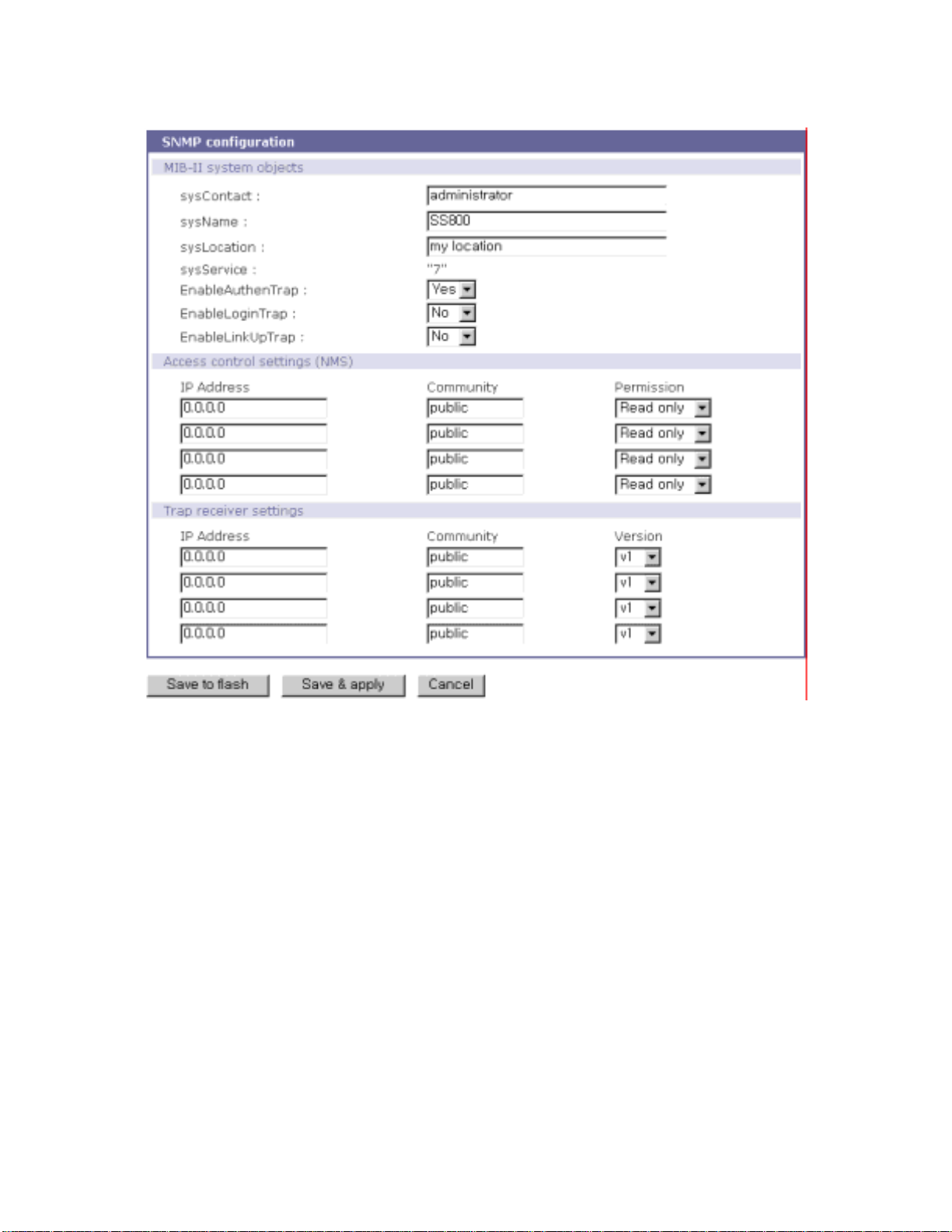
Figure 3-2 SNMP Configuration
3.2.1. MIB-II System objects Configuration
MIB–II System objects configuration sets the System Contact, Name, Location, and Authenticationfailure traps used by the SNMP agent of the STS Series. These settings provide the values used for
the MIB-II sysName, sysContact, sysLocation, sysService and enableAuthenTrap.
Brief descr i ptions of each object ar e as f ol l o ws ,
sysContact: Identification of the contact person for the managed system (STS Series), and a
description of how to contact the person.
sysName: Name used to identify the system. By convention, this is the fully qualified domain
name of the node.
sysLocation: The physical location of the system (e.g., Room 384, Operations Lab, etc.).
sysService(Read Only) : A series of values, separated by commas, that indicate the set of
26
Page 27

services that the system provides. By default, STS Series only supports an Application(7)
service level.
EnableAuthenTrap: Indicates whether the SNMP agent process is permitted to generate
authentication-failure traps. The value of this object overrides any configuration information; as
such, it provides a means whereby all authentication-failure traps may be disabled..
EnableLinkUpTraps: Indicates whether the SNMP agent process is permitted to generate
Ethernet-link traps
EnableLoginTrap: Indicates whether the SNMP agent process is permitted to generate system
login traps.
If users need support for adding or modifying MIBs, please contact Sena technical support.
For more information about the MIBs and SNMP, see the RFCs 1066, 1067, 1098, 1317, 1318
and 1213.
3.2.2. Access Control Configuration
Access Control defines accessibility of managers to the STS Series SNMP agent. Only the manager
set in this menu can access STS Series SNMP agent to exchange information and control actions. If
there is no specified IP address (all IP address are defaulted to 0.0.0.0), a manager from any host can
access the STS Series SNMP agent.
3.2.3. Tr ap Receiver Configuration
The Trap receiver defines managers, which can be notified of significant events(TRAP) from the STS
Series SNMP agent.
3.2.4. Management using SNMP
The STS Series can be managed through the SNMP protocol using NMS (Network Management
System) or SNM P Browser. Before using the NMS or SNMP Browser, the user must set the access
control configuration properly so that the STS Series permits host access where the NMS or SNMP
Browser is executed. Figure 3-3 shows a screen shot of a typical SNMP browser with MIB-II OIDs of
the STS Series SNMP agent.
27
Page 28
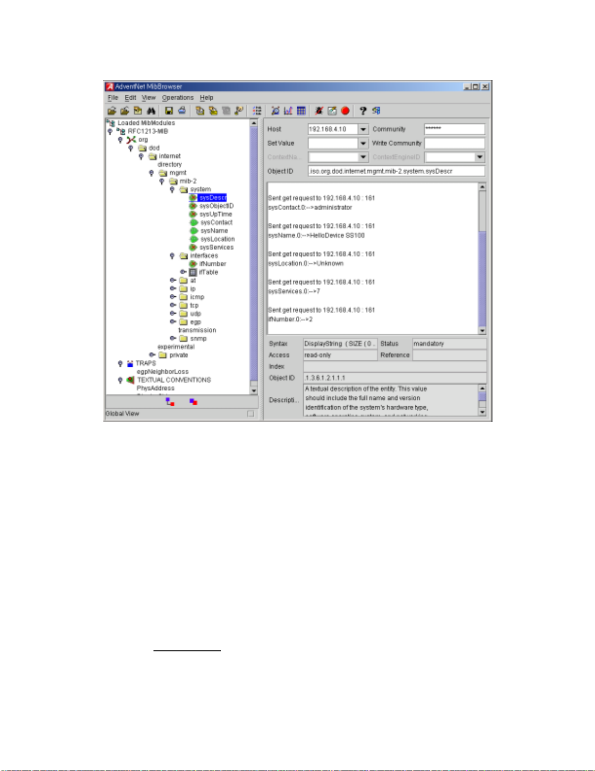
Figure 3-3 Browsing MIB-II OIDs of STS Series SNMP agent using SNMP Browser
(AdventNet MibBrowser)
3.3. Dynamic DNS Configuration
When users connect the STS Series to a DSL line or use a DHCP configuration, the IP address might
be changed whenever it reconnects to the network. It can therefore be very difficult to post all related
contacts for each new IP address. In addition, if the administrator only has access through the remote
console, there is no way to know if an IP address has changed, or what the new IP address is.
A Dynamic DNS service is provided by various ISPs or organizations to deal with the above issue.
By using the Dynamic DNS service, users can access the STS Series through the hostname
registered in the Dynamic DNS Server regardless of any IP address change.
By default, the STS Series only supports Dynamic DNS service offered at Dynamic DNS Network
Services, LLC (www.dyndns.org
DNS service providers.
To use the Dynamic DNS service provided by Dynamic DNS Network Services, the user must set
up an account in their Mem bers' NI C (Network Inform ation Cent er - http: //member s.dynd ns. org). T he
). Contact Sena technical support for issues regarding other Dynamic
28
Page 29
user may then add a new Dynamic DNS Host link after logging in to their Dynamic DNS Network
Services Members NIC.
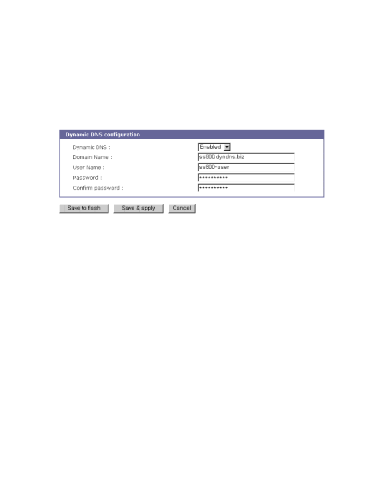
After enabling the Dynamic DNS service in the Dynamic DNS Configuration menu, the user must
enter the registered Domain Name, User Name, and Password. After applying the configuration
change, users can access the STS Series using only the Domain Name.
Figure 3-4 shows the Dy namic DNS configuration web interface.
Figure 3-4 Dynamic DNS Configuration
3.4. SMTP Configuration
The STS S eries can s end an email not ificat ion when the nu mber of sys tem log mess ages reaches to
certain value and/or when an alarm message is created due to an issue with serial port data. The user
must configure a valid SMTP server send these automatically generated emails. The STS Series
supports three SMTP server types:
• SMTP without authentication
• SMTP with authentication
• POP-before-SMTP
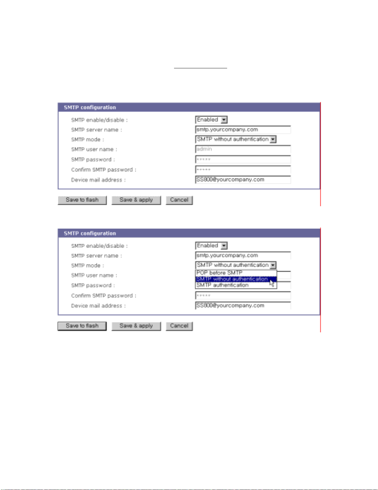
These examples can be seen in Figure 3-6. Required parameters for each SMTP configuration
include:
• SMTP server IP address
• SMTP user name
• SMTP user password
• Device mail address
The device mail address specifies the sender’s email address for all log and alarm delivery emails.
SMTP servers often check only the sender’s host domain name of the email address for validity.
29
Page 30
Consequently, the email address set for the device can use an arbitrary username with a registered
hostname (i.e. [email protected] or [email protected]
The SMTP user name and SMTP user password are required when either SMTP with
authentication or POP-before-SMTP mode is selected.
Figure 3-5 SMTP Configurations
).
Figure 3-6 SMTP mode selection in SMTP configuration
3.5. IP Filtering
The STS Series prevents unauthorized access using either an IP address based filtering method or
through the management web page of the STS Series. The users can allow one of the following
scenarios by changing the parameter setti ngs:
- Only one host of a specific IP address can access the STS Series
- Hosts on a specific subnet can access the STS Series
- Any host can access the STS Series
30
Page 31
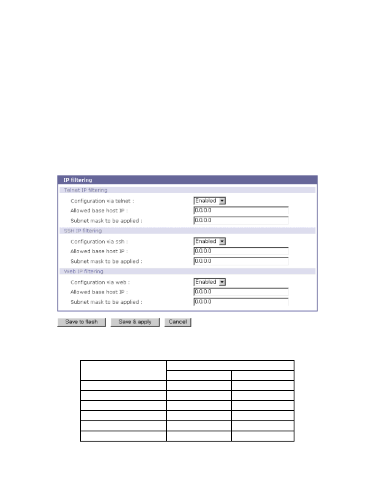
The IP filteri ng fe ature for acc ess t o Telnet cons ole, SSH cons ole or Web ser ver m ay be ena bled
or disabled. The factory default of the filtering feature is “Enabled”.
The user may allow a host or a group of hosts to access the STS Series for configuration. The
user must then enter the IP address and subnet of access. Any user on a remote host must stay in the
specified subnet boundary to have the configuration access.
To allow only a specific host to have configuration access to the STS Series, enter the IP address
of the specific host and just give 255.255.255.255 for the subnet
To allow any hos ts to hav e access to t he STS Series , give 0.0 .0.0 for bo th of the IP address and
subnet. Refer to Table 3-2 for more details. The device’s default settings for allowed remote hosts for
configuration is “Any”.
Figure 3-7 IP filtering Configuration
Table 3-2 Input examples o f allowed remote h osts
Allowable Hosts
Base Host IP address Subnet mask
Any host 0.0.0.0 0.0.0.0
192.168.1.120 192.168.1.120 255.255.255.255
192.168.1.1 ~ 192.168.1.254 192.168.1.0 255.255.255.0
192.168.0.1 ~ 192.168.255.254 192.168.0.0 255.255.0.0
192.168.1.1 ~ 192.168.1.126 192.168.1.0 255.255.255.128
192.168.1.129 ~ 192.168.1.254 192.168.1.128 255.255.255.128
31
Input format
Page 32
Web access also uses the IP filtering function, which can be enabled or disabled. The factory default
setting is “Enabled”. When enabled, the user can specify a web host or hosts allowed to access the
STS Series for configuration.
3.6. SYSLOG server configuration
The STS Series supports a remote message logging service, SYSLOG service for the system and port
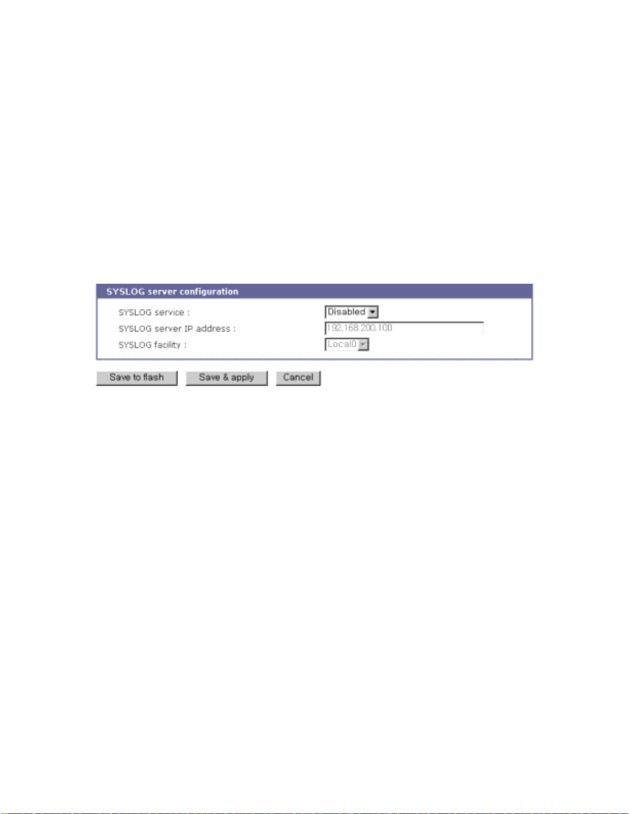
data logging. To use the remote SYSLOG service, the user must specify the SYSLOG server’s IP
address and the facility to be used. Figure 3-8 shows the SYSLOG server configuration page of the
supplied Web in t e rface.
Figure 3-8 SYSLO G se rv er c o nf iguration
To receive log messages from the STS Series, the SYSLOG server must be configured as “remote
reception allowed”. If there is a firewall between the STS S eries and the SYSLOG server, there must
be a rule that allows all outgoi ng and incoming UDP packets to travel across the firewall.
The STS S er i es s upp ort s SYS LO G fa ci lit ies f rom local0 to local7. The us er c an empl o y thes e
facilities to save messages from the STS Series separately in the SYSLOG server.
If the SYSLOG service is enabled and the SYSLOG server configuration is properly set up, the
user may configure the storage location for the system log or port data log of the STS Series as
SYSLOG server. For more information about the configuration of port/system log storage location,
please refer to section, 4.2.10 Port Logging and 6.2 System Logging.
3.7. NFS server configuration
The STS Series supports NFS (Network File System) service for system or port data logging
functions. To use this service, the user must specify the IP address of a NFS server and the mounting
path on the NFS server. Figure 3-9 shows the web based NFS server configuration page.
32
Page 33
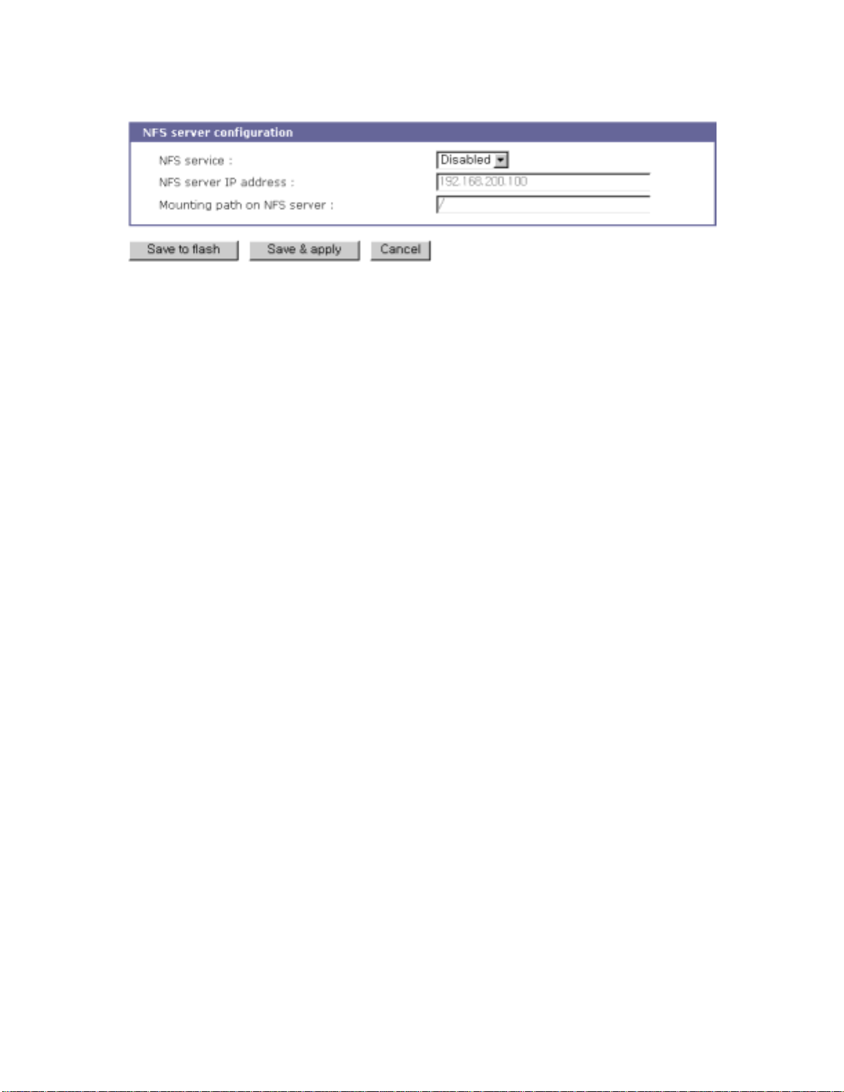
Figure 3-9 NFS server configuration
To store the STS Series log data to the NFS server, the NFS server must be configured as “read and
write allowed”. If there is a firewall between the STS Series and the NFS server, there must be a rule
that allows all outgoing and incoming packets to travel across the firewall.
If the NFS service is enabled and the NFS server configuration is properly set up, the user may
configure the storage location for the system log or port data log of the If there is a firewall between
the STS Series and the SYSLOG server, there must be a rule that allows all outgoing and incoming
UDP packets to travel across the STS Series as the NFS server. For more information about the
configurat ion of the port/ system log sto rage location , please refe r to section, 4.2.10 Port Logging and
6.2 System Logging.
3.8. Ethernet configuration
The STS Series supports several types of Ethernet modes:
- Auto Negotiation
- 100 BaseT Half Duplex
- 100 BaseT Full Duplex
- 10 BaseT Half Duplex
- 10 BaseT Full Duplex
After changing the Ethernet mode, the user must reboot the system. The factory default value of the
Ethernet mode is Auto Negotiation. With most network environments, Auto Negotiation mode works
fine and is recommended. Invalid Ethernet mode configuration may make the STS Series not work in
the network e nv i r o nm e n t .
33
Page 34
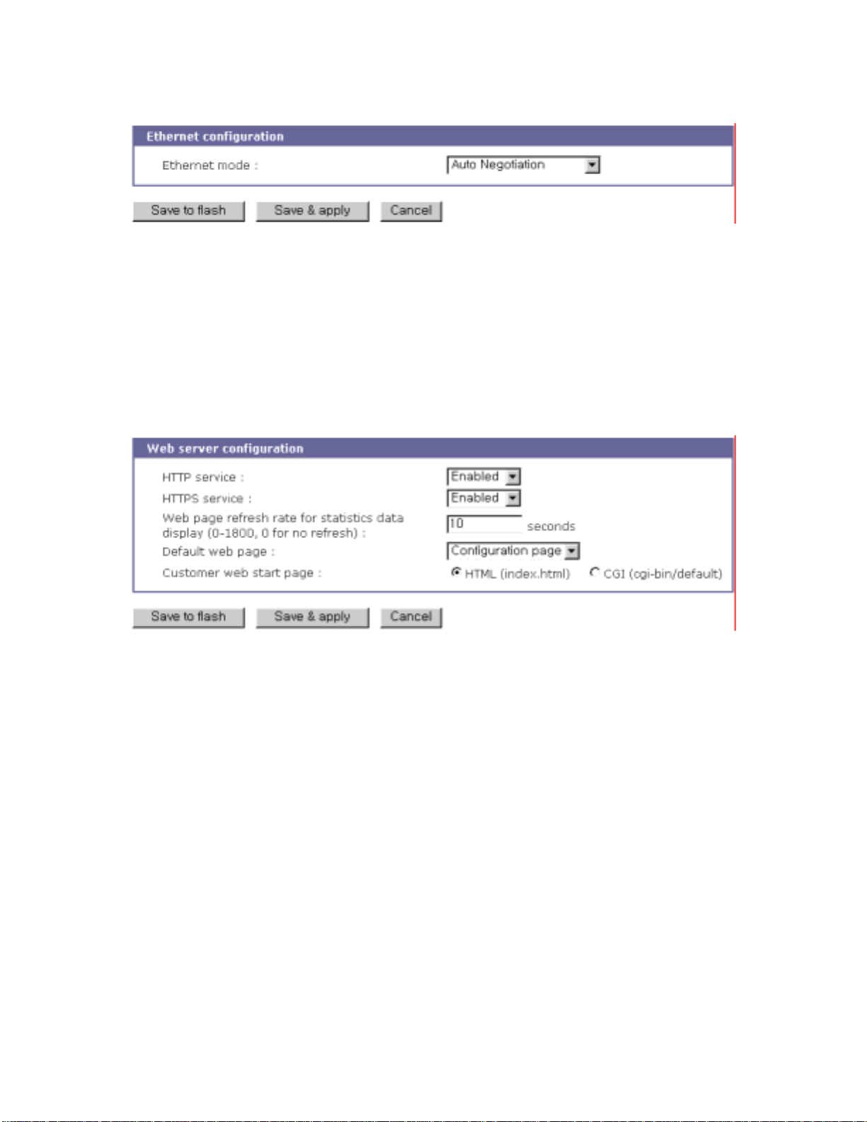
Figure 3-10 Ethernet mode configuration
3.9. Web server configuration
The Web server supports both HTTP and HTTPS (HTTP over SSL) services simultaneously. The user
can opt to enable or disable each individually. Figure 3-11 shows the Web server configuration page.
Figure 3-11 Web server configurations
The Web page refresh rate c an be also adjusted in this configu ration page. T he refresh rate is only
applicable to the system statistics pages, such as network interfaces, serial ports, IP, ICMP, TCP and
UDP. Other pages in the Web interface are not refreshed automatically. For more information about
the system statistics, please refer to section 7 System Statistics.
3.10. TCP service configuration
If a TCP session is established between two hosts, it should be closed (normally or abnormally) by
either of the hosts to prevent the lock-up of the corresponding TCP port. To prevent this type of lockup situation, the STS Series provides a TCP “keep-alive” feature. The STS Series will send packets
back and forth through the network periodically to confirm that the network is still alive. The
corresponding TCP session is closed automatically if there’s no response from the remote host.
To use the TCP “keep-alive” feature with the STS Series, the users should configure three
34
Page 35
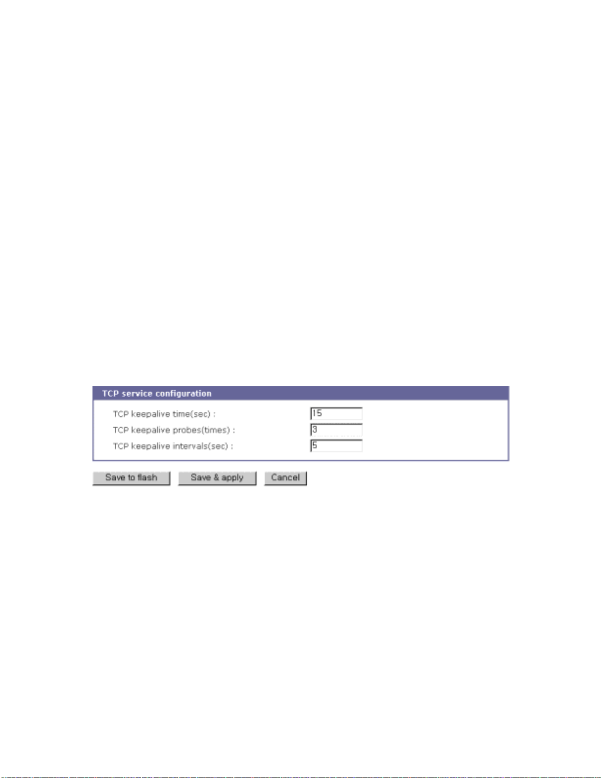
parameters as follows:
TCP keep-alive time:
This represents the time interval between the last data transmission and keep-alive packet
submissions by the STS Series. These “keep-alive” messages are sent to the remote host to
confirm that the session is still open. The default time value is 15 sec.
TCP “keep-alive” probes:
This represents how many “keep-alive” probes will be sent to the remote host, until it decides that
the connection is dead. Multiplied with the “TCP ‘keep-alive’ intervals”, this gives the time that a
link is forced to close after a “keep-alive” packet has been sent for the first time. The default is 3
times
TCP keep-al ive i nt e rvals:
This represents the waiting period until a “keep-alive” packet is retransmitted due to no
acknowledgement by the original Chinatown. The default value is 5 seconds.
By default, the STS Series
will send the keep-alive packets 3 times with 5 seconds interval after 15
seconds have elapsed since the time when there’s no data transmitted back and forth.
Figure 3-12 TCP keep-alive configuration
35
Page 36

4. Serial Port Configuration
4.1. Overview
The serial port configuration capability allows the user to configure the host mode of each port, serial
communication parameters, cryptography, port logging parameters and other related parameters.
The serial port’s host mode can be set as any of the following:
TCP :
The STS Series operates as a TCP server and client. If the connection is not established, it
accepts all incoming connections from any registered remote hosts and connects to the registered
remote hosts if there is any data from the serial devices. Otherwise, it will send data back and
forth. In summary, the STS Series will work as if it is virtually connected to the remote host.
UDP
:
The UDP mode operation is similar to that of TCP mode except that it is based on UDP protocol.
Modem emulation :
Select this mode when the serial device already supports modem AT commands or users want to
perform the session control by using AT commands. Only TCP session is supported.
Virtual COM
:
This feature will be added later.
With the
port-logging
transferred to
MEMORY, SYSLOG server, NFS server’s storage
feature while in console server mode, the data sent through the serial port is
or an
ATA/IDE fixed disk card
using a PC Card slot. The user can also define keywords for each serial port that will trigger an email
or SNMP trap notification. This will enable the user to monitor the data from the attached device.
Using
MEMORY
off. Use the
NFS server
to store data will result in loss of all information when the STS Series is turned
or
ATA/IDE fixed disk card
to preserve the serial port log data.
The serial ports can be configured individually or all at once. Table 4-1 summarizes the
configuration parameters related to the serial port configuration.
Table 4-1 Serial port configuration parameters
All serial
ports
setting
Or
Individual
Port Enable/Disable
Port title
Apply all port settings (Individual serial port setting only)
Host mode TCP
TCP listening port
Telnet protocol
Max allowed connection
Cyclic connection
36
Page 37

serial port
setting
#1~#8(1/4)
Remote host1
Port IP filtering3
Cryptography4
Serial Port
Parameters
Modem
Port logging
Port event handling
Inactivity timeout (0 for unlimited)
UDP listening port
Max allowed connection
UDP
Accept UDP data gram from unlisted remote
host or not
Send to recent unlisted remote host or not
Inactivity timeout (0 for unlimited)
Modem emulation
Add or Edit a remote host2
Primary host address
Primary host port
Secondary host address
Secondary host port
Remove a remote host
Allowed host IP
Subnet mask to be applied
Encryption method
None/SSLv2/SSLv3/SSLv3 rollback to v2/
TLSv1/3DES/RC4
Cipher suite selection
Verify client (server mode only)
Verify certificate chain depth
Check the certificate CN
Type
Baud rate
Data bits
Parity
Stop bits
Flow control
DTR behavior
DSR behavior
Inter-character timeout (ms)
Enable/Disable modem
Modem init-string
DCD behavior
Enable/Disable Port logging
Port log storage location
Port log buffer size
Display port log
Enable/Disable port event handling
Notification interval
Email
notification
Enable/Disable Email notification
Title of Email
Recipient’s Email address
Enable/Disable SNMP notification
SNMP
notification
Title of SNMP trap
SNMP trap receiver’s IP address
SNMP trap community
SNMP trap version
1
TCP/UDP mode only.
2
A secondary remote host is available for connection-fail backup in TCP mode
3
TCP/UDP mode only.
4
TCP mode only
37
Page 38
Add/Edit a keyword
Keyword string
Email notification
SNMP trap notification
Port command
Remove a keyword
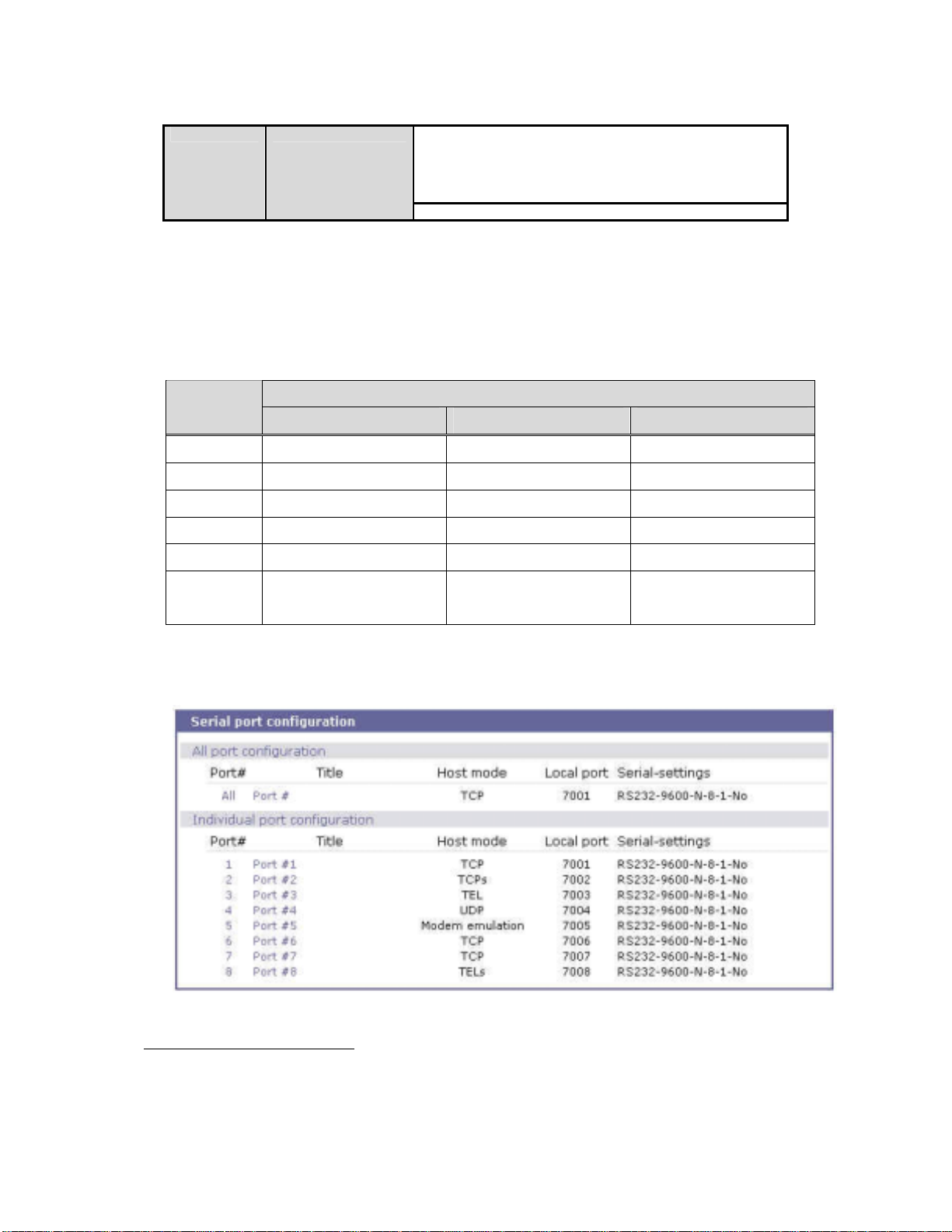
Figure 4-1 shows the web-based serial port configuration screen. This serial port configuration main
screen summarizes port information. In this summary page, user can find how host mode, encryption
option, local port number and serial port parameters are configured at a time. In this page, the
meaning of string on Host mode column is as follows,
Host mode
Description
Mode5 Encryption6 Telnet7
TCP
TCPs
TEL
TELs
UDP
TCP Disabled Disabled
TCP Enabled Disabled
TCP Disabled Enabled
TCP Enabled Enabled
UDP *
8
*
Modem
Modem Emulation * *
Emulation
To select and configure a serial port individually, click the port number or title. To configure all of
the serial ports at once, click [All] or [Port Title], located below the [All port configuration] label.
Figure 4-1 Serial port configuration main screen
5
See section 4.2.4 Host Mode Configuration
6
See section 4.2.7 Cryptography configuration
7
See section 4.2.4.1 TCP mode
8
Not support
38
Page 39
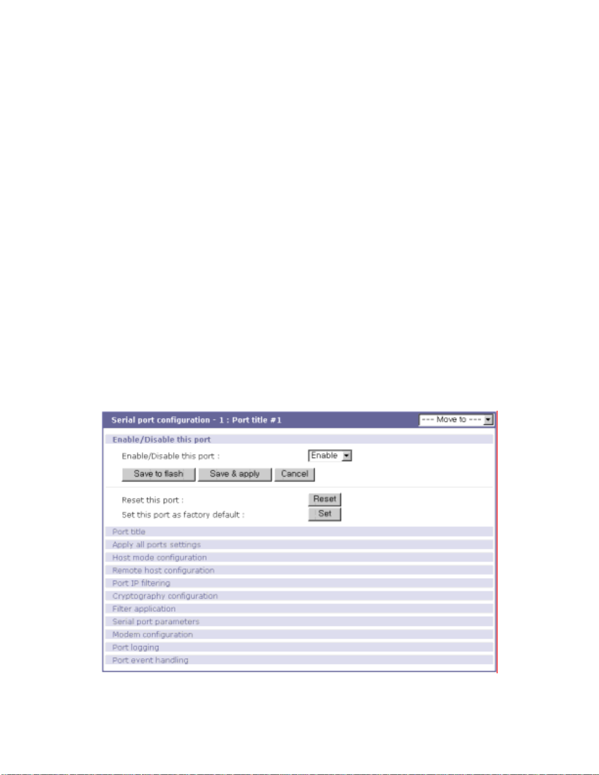
4.2. Individual Port Configuration
The STS Series allows serial ports to be configured either individually or all at once. The parameters
for both
Users can switch to another serial port configuration screen conveniently using the [--- Move to ---] list box at
the right upper side of the individual port configuration screen.
individual
Individual Port Configurations are classified into nine (9) groups:
1. Port enable/disable
2. Port title
3. Apply all port settings
4. Host mode
5. Remote host: Available only when the host mode is set to TCP or UDP mode
6. Port IP filtering: Available only when the host mode is set to TCP or UDP mode
7. Cryptography: Available only when the host mode is set to TCP mode and Modem
8. Serial port parameters
9. Modem configuration
10. Port logging
11. Port event handling: Available only when the port-logging feature of the port is enabled
and
all port configurations
Emulation mode
are similar.
Figure 4-2 Serial port enable/disable
39
Page 40
4.2.1. Port Enable/Disable
Each serial port can be enabled or disabled. If a serial port is disabled, users cannot access the serial
port. Figure 4-2 shows the serial port enable/disable screen.
By clicking on the [Reset] button, users can reset a stuck or deadlocked serial port. Click on the
[Set] button to set the port as fact ory default.
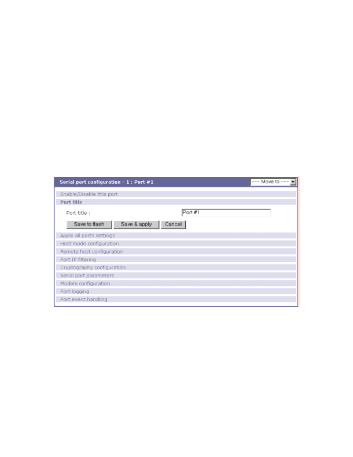
4.2.2. Port Title
Users can enter descriptive information for each port based on the device attached to it. This can
include the device type, vendor, and/or location. The port title is helpful in the configuration process,
Figure 4-3 Port title configuration
4.2.3. Apply All Port Settings
To prevent the possibility of the user inadvertently selecting to change all port settings at the same
time, the STS Series provides the ability to enable or disable this function at an individual serial port
level. Changes made when using the “change all port parameters at once” function will not be applied
to an individ ual seri al port if th e func ti on has be en di sab le d (S ee F igu re 4- 4. This shows the
port setting]
configuration screen.
40
[apply all
Page 41
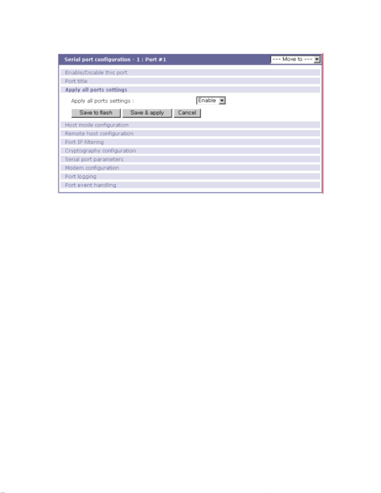
Figure 4-4 Apply all port setting configuration.
4.2.4. Host Mode Configuration
The STS Series operating mode is called the “host mode.” Three host modes are available: TCP
mode, UDP mode, Modem emulation mode
TCP mode
The STS Series works as both TCP server and client. This mode works for most applications,
since it will transfer the data either from serial port or from TCP port. If there is no connection
established o n a TCP port, the TCP port accepts a connect ion request from any regis tered remote
hosts and relays the transmitted data to the coupled serial port. If there is any data from the serial port,
it connects to the registered remote hosts and redirects the data.
UDP mode
The UDP mode operation is similar to that of TCP mode except that it utilizes UDP protocol
.
Modem emulation mode
Select this mode when the serial device already supports modem AT commands or users want to
perform the session control by using AT commands. Only TCP session is supported.
Figure 4-5 shows the main workspace screen for the host mode configuration.
41
Page 42
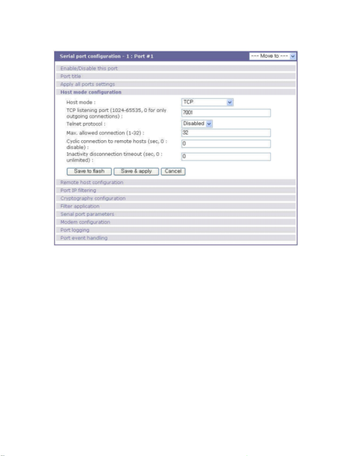
Figure 4-5 Host mode configuration
4.2.4.1. TCP mode
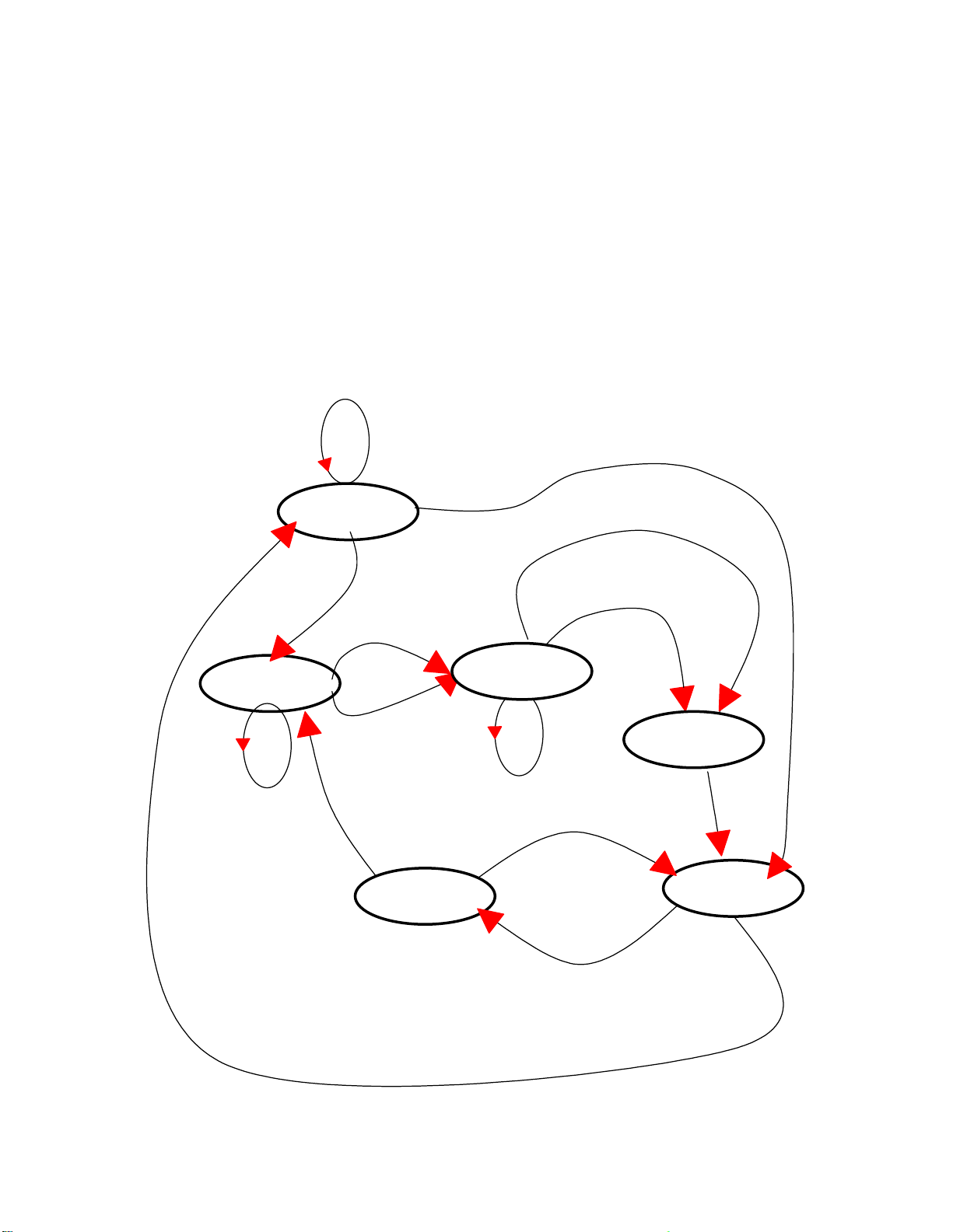
For easier understanding of TCP modes, a simplified State Transition Diagram is often used. And to
help users understand the diagram, the TCP state of the STS Series is briefly described as follows.
- [Listen]
It represents “a waiting for a connection request from any registered remote host”. It is a default
start-up mode when it is set as TCP mode.
- [Closed]
It means “no connection state”. If the data transfer between a remote host and the STS Series is
completed, the state is changed to this state as a result that either of the remote host or the STS
Series sent a disconnection request. After this, the state is automatically changed to [Listen] mode.
- [Sync-Received]
The state is changed from [Listen] to [Sync-Received] if one of the remote hosts has sent a
connection request. If the STS Series accepts the request, the state is changed into [Established].
- [Sync-Sent]
42
Page 43

If the STS Series has sent a connection request to a remote host, the state is changed from
[Closed] to [Sync-Sent]. This state is maintained until the remote host accepts the connection
request.
- [Established]
It represents “an open connection”. If one of the hosts, the remote host or the STS Series,
accepts a connection request from the other, the connection is opened and state is changed into
[Established].
- [Data]
When it is in [Established] state, data from a host will be transferred to the other one. For easier
understanding of the TCP session operation, we called the state as [Data] state when actual data
transfer is performed. Actually, the [Data] mode is a part of [Established] state as is described in
the RFC 793 [Transmission Control Protocol]. This is a normal state for the data transfer phase of
the connection.
The STS Series works as either TCP server or client according to the situation. This will be the typical
mode for most applications, since it will transfer the data either from serial port or from TCP port. The
default TCP state is [Listen] which is the same as that of TCP server mode.
1) Typical State Transition
[Listen] --> [Sync-Received] --> [Established] --> [Data] --> [Closed] --> [Listen]
Or
[Listen] --> [Sync-Sent] --> [Established] --> [Data] --> [Closed] --> [Listen]
The initial s tate is [Listen] . If there are data c oming from the s erial port, it will connect to th e remote
host as a TCP client and then transfer data through the TCP port. If there is incoming connection
request from the remote host, it will accept the connection as a TCP server, and then transfer data
through the serial port. Thus, users can assume that the STS Series is always connected to the
specified remote host.
2) Operations
Serial data transfer
Whenever the serial device sends data through the serial port of the STS Series, data will be
accumulated on the serial port buffer of the STS Series. If the buffer is full or the time gap reaches
the inter-character timeout (See Options in section 4.4 for details on inter-character timeout), the
STS Series connect to the registered remote host(s). If a TCP session has not been established
yet. If the STS Series succeeds in connecting to the remote host, the data in the serial port buffer
will be transferred to the host. Otherwise, all the data stored in the buffer will be cleared.
Session disconnection
43
Page 44

The connected session will be disconnected when the remote host sends disconnection request
or when no data transfer activity is found through the serial port for certain amount of time, which
is “Inactivity timeout” (See Options in section 4.4 for details on Inactivity timeout). All the data
remained in the serial port buffer will be cleared when it is disconnected.
Connection request from remote host
All the incoming TCP connection requests will be rejected in TCP client mode.
3) Parameters
TCP listening port
This is the TCP port number through which remote host can connect a TCP session, and, send
and receive data. Incoming connection request to the ports other than TCP Listening Port will be
rejected. The STS Series does restrict the port number from 1024 to 65535 and if it is set as 0
only outgoing connection is permitted. (TCP server mode)
Telnet protocol
In TCP mode, STS Series support Telnet Com Port Control Option (RFC2217 compliant) so that
user can control serial parameters like baud rate, data bits and flow control option using his local
RFC2217-compliant Telnet client program. (Please refer to section 4.2.8 Serial port parameters
for more detail information about serial parameters)
Usually this option is used with the RFC2217-compliant COM port redirector so that user can
control parameters of serial ports of STS Series using his serial port application program.
For this purp ose, SENA OEM version of Serial/IP from Tactical Soft war e, LLC is bundled with STS
Series. Please refer to documentations of Serial/IP for more detail information about using the
COM port redirector. (Please refer to section Appendix 6Using STS Series with Serial/IP for more
detail information)
Max. allowed connection
The STS Series supports multiple c onnections from ext e r na l ho s t ( s ) t o a serial port up to 32. B ut if
there are remote host connections by the remote host list configuration already, possible number
of connection is reduced to (Max. allowed connection - remote host(s) connected already). For
example, if user set Max. allowed connection as 32 and if there are 3 connections from STS
Series to remo te hosts, which are confi gured in the remote host list, then maximum numbe r of
connection from external hosts to a serial port will be reduced to 29 (=32 – 3). For more detail
information for remote host list configuration, please refer to 4.2.5 remote host list configuration
section.
Cyclic Connection
If Cyc lic Connection function is enabled, the STS Series will make an attempt to connect to the
44
Page 45
user-defined remote host(s) at a given interval even if there’s no incoming serial data from the
device connected to that serial port. If there is data on the remote host(s) to be sent to serial
device, it can be transferred to the serial device via STS Series’s serial port after the connection is
established. Eventually, users can monitor the serial device periodically by making the remote
host send the serial command to the STS Series whenever it is connected to the remote host.
This option is useful when users need to gather the device information periodically even if the
serial devi ce d oes not sen d its data p eri odi call y. Figure 4-6 s ho ws t he State Transiti on Di agr am o f
the session operations in TCP mode.
TCP connection request rejected
Or internal TCP time-out
TCP connection request accepted
Established
Sync-Sent
Incoming data via serial port
Incoming data
from remote host
Accept
Sync-Recvd
In-coming TCP Close request
Inactivity time-out
Data
Closed
Reject
Listen
Incoming TCP connection request
Incoming data via serial port
Figure 4-6 State Transition Diagram of TCP mode
45
Page 46

Inactivity Timeout
When Inactivity Timeout function is enabled, connection between remote host(s) and STS Series
will be closed automatically if there is no data transmission during the value which is set in
Inactivity Timeout configuration.
4.2.4.2. UDP mode
The UDP mode operation is similar to that of TCP mode except that it is based on UDP protocol and
only one pre-defined remote host is able to communicate with the STS Series. Users do not have to
configure cyclic connection, since UDP is a connectionless protocol.
1) Operations
If a remote ho st sends a U DP datagram to t he one of UD P Local port of the STS Series, STS Series
first checks whether it is from one of the hosts configured on remote host configuration. If the remote
host is one of the hosts configured on remote host configuration, then STS Series transfers the data
through the serial port. Otherwise, the STS Series discards the incoming UDP datagram. But user can
force STS Series accept all incoming UDP datagram regardless remote host co nfiguration by setting
Accept UDP datagram from unlisted remote host parameter as ‘Yes’. If there is any inc o ming data from
the serial port, the STS Series transfers the data to the remote host defined on remote host
configuration. If the remote port is not opened, the STS Series will not transfer the data.
2) Parameters
UDP receiving port
The concept is the same as TCP listening port. See
TCP mode parameters
in the sect ion 4 .2.4.1
for details.
Max. allowed connection
The concept is the same as that of TCP communication.
TCP mode parameters
in the section
4.2.4.1 for details.
Accept UDP datagram from unlisted remote host
If Accept UDP datagram from unlisted remote host function is set as ‘No’, STS Series will accept
only incoming UDP datagram from the remote host(s) configured on remote host configuration.
On the contrary if Accept UDP datagram from unlisted remote host function is set as ‘Yes’, STS
Series will accept all incoming UDP datagram regardless remote host configuration.
Send to recent unlisted remote host
46
Page 47

If Send to recent unlisted remote host function is set as ‘Yes’, STS Series sends data to the
remote host, which has connected STS Series recently. Recent unlisted remote host is a remote
host, which has accessed a corresponding serial port of STS Series but is not configured on
remote host configuration. Surely, STS Series also send data to the hosts, which are configured
on remote host configuration. If Send to recent unlisted remote hos t function is set as ‘No’, STS
Series sends data only to the host(s) which are configured on remote host configuration. STS
Series maintains a recent unlisted remote host during the Inactivi ty Ti meo u t.
Inactivity Timeout
In UDP mode, Inactivity Timeout is used in maintaining recent unlisted remote host. If there is no
data transmission between unlisted remote host and serial port of STS Series during Inactivity
Timeout, STS Series will not send data from a serial port to the recent unlisted remote host again.
Namely, Inactivity Timeout in UDP mode is the time maintained recent unlisted remote host list by
STS Series. If user set Inactivity Timeout as 0 in UDP mode, STS Series does not send any data
from serial port to unlisted remote host.
4.2.4.3. Modem emulation mode
In modem emulation mode, the serial port process acts as if it is a modem attached to the serial
device. It accepts AT modem commands and answers to them, as modems would do. It also handles
the modem signals correctly. Modem emulation mode is useful in the following cases.
- There already exists a modem attached to the users’ serial device.
If users’ serial device already has a modem for phone-line connection, it can be just replaced by
the STS Series for Ethernet connection. What users need to do is to use an IP address (or
domain name) instead of phone number as a parameter of ATA/ATDT commands.
- It is required to send serial data to the multiple remote hosts.
If the serial device should send data to the multiple hosts, modem emulation mode is required.
For example, the first data from the serial device can be sent to the first data acquisition server
and the second to the second server. What user device has to do is to change the IP address (or
domain name) parameter whenever the device sends ATD(T) XXX command.
By using the modem emulation mode of the STS Series, users can have their serial device connected
to the Ethernet network easily, which is cheaper than using phone line modem. Table 4-2 is a
summarized AT command table which is supported by the STS Series. Figure 4-7 shows the typical
case of the serial port command flow when ATDA command is used to connect to the Ethernet network.
47
Page 48

Table 4-2 AT commands supported in the STS Series
Command Internal Operation
+++ Return to command input mode None
ATD(T)
[remote IP or domain
name]:[remote port]
[CR][LF]
AT or ATZ [CR][LF] Initialize TCP soc ket an d serial po rt
ATA/ [CR][LF] Repeat last command
ATA
[Local port number]
[CR][LF]
AT E n [CR][LF]
ATHn [CR][LF]
ATOn [CR][LF] O, O0: Turn to data mode
ATQn [CR][LF]
AT V n [CR][LF]
AT&Dn [CR][LF]
AT&Fn [CR][LF] F, F0, F1: Restore default modem settings
AT & Kn [CR][LF]
AT & Sn [CR][LF]
ATIn [CR][LF]
AT\Tn [CR][LF]
ATBn, ATCn, ATLn, ATMn,
ATNn, ATP, ATT, ATYn,
AT%Cn, AT%En, AT&Bn,
AT&Gn, AT&In, AT&Qn,
AT&V, AT}Mn, AT\An,
AT\Bn, AT\Nn
ATS?, ATSn=x, AT&Cn,
AT&Wn, AT&Zn=x
Set TCP mode as TCP client mode. And then, try to connect
to the specified remote host.
e.g. atdt192.168. 1 .9 :100 2:
Connect to IP address, 192.168.1.9, port 1002
e.g. atdt
Connect to the remote host using the parameters specified
Set TCP mode as TCP server mode. And then, set TCP state
as [Listen].
-. If the command parameter, Local port number is not
specified, the TCP session parameter, Local Port is used
instead.
E, E0: Disable echo
E1: Enable echo
H, H0, H1: Disconnect current T CP connection
All the data will be cl eared
Q, Q0: Response display on (default)
Q1: Response display off
V, V0: Response = <numeric code> [CR][LF]
V1 (default): Res p on se = <ver b o se cod e> [CR ][ LF]
D, D0: ignore DTR(PC) signal
D2(default): disconnect TCP session
K, K0: No flow control
K3: RTS/CTS flow control (default)
K4: Xon/Xoff (if supported)
S, S0: DSR(PC) always high
S1: DSR(PC) shows TCP connection
I, I0 : display “Sena T echnologies, Inc.”
I3 : display model number
Others : display “OK”
Set inactivity timer to n minutes
\T, \T0: inactivity timer disabled (default)
none OK [CR][LF]
none ERROR [CR][LF]
Response 9
(Verbose Code)
If successful,
CONNECT [CR][LF]
If failure in connection,
NO CARRIER [CR][LF]
If other errors,
ERROR [CR][LF]
If successful,
OK [CR][LF]
If failure,
ERROR [CR][LF]
If successful,
OK [CR][LF]
If failure,
ERROR [CR][LF]
<=
OK [CR][LF]
9
If Echo mode is enabled, the command will be sent back first. And then, corresponding response will be sent. If disabled, only
response will be sent.
48
Page 49
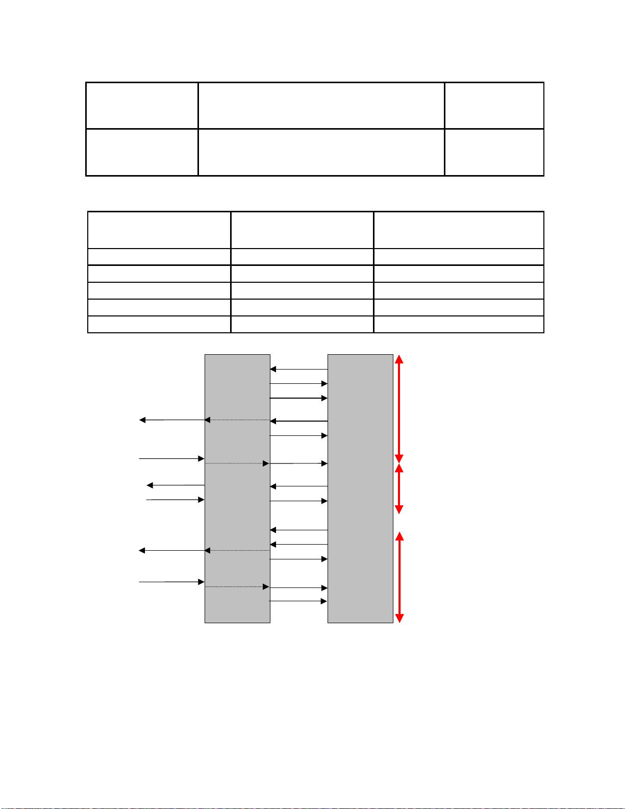
ATFn [CR][LF] None
ATZA
A
A
A
A
ATWn , A TXn None
If n=1
OK [CR][LF]
If others,
ERROR [CR][LF]
If n=0
OK [CR][LF]
If others,
ERROR [CR][LF]
Table 4-3 AT commands Response Code
Verbose Code
(After “ATV1” command executed)
Numeric Code
(After “ATV0” command executed)
Description
OK 0 Command executed
CONNECT 1 Modem connected to line
RING 2 A ring signal has been detected
NO CARRIER 3 Modem lost carrier signal
ERROR 4 Invalid command
TCP connection
Request
TCP connection
Established.
DATA….
DATA….
HelloDevice
SS100
TZ
OK
TDT
TDT
CONNECT
DATA….
DATA….
Serial
Device
Command mode
TCP mode
+++
Request TCP
disconnection
TCP
disconnection
TH
TH
Command mode
OK
NO CARRIER
Figure 4-7 T ypical case of co mmand/data flow of modem emulation mode
4.2.5. Remote host configuration
Remote host configuration is the list of hosts that will receive data from serial port of STS Series when
there is data transmission from a serial port of STS Series.
49
Page 50
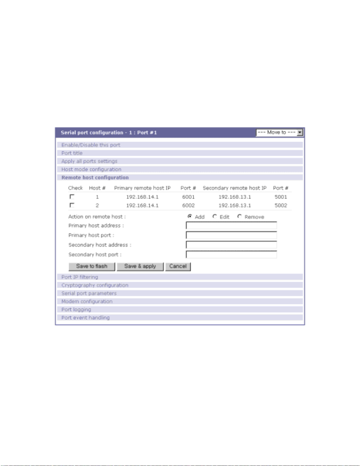
In TCP mode, user can also configure secondary remote host that will receive data from serial
port if STS Series fails to connect to primary remote host. But if connection to primary remote host can
be made, STS Series dose not send data to secondary remote host until connection to primary remote
host failed. And the maximum possible number of primary remote host is limited up to 16.
In UDP mode, user can configure only primary remote host because there is no way for STS
Series to check status of primary remote host, so secondary remote host is meaningless.
Figure 4-8 shows Remote host configuration pages of the Web UI. (TCP mode)
Figure 4-8 Remote host configuration
4.2.6. Port IP filtering configuration
The remote hosts that are allowed to access the STS Series serial ports can be specified based on the
IP address filtering rules. The user may allow specific hosts to access the STS Series s erial ports by
providing a valid IP address or network address and its subnet mask. Please refer to section 3.5 IP
Filtering for more details.
50
Page 51
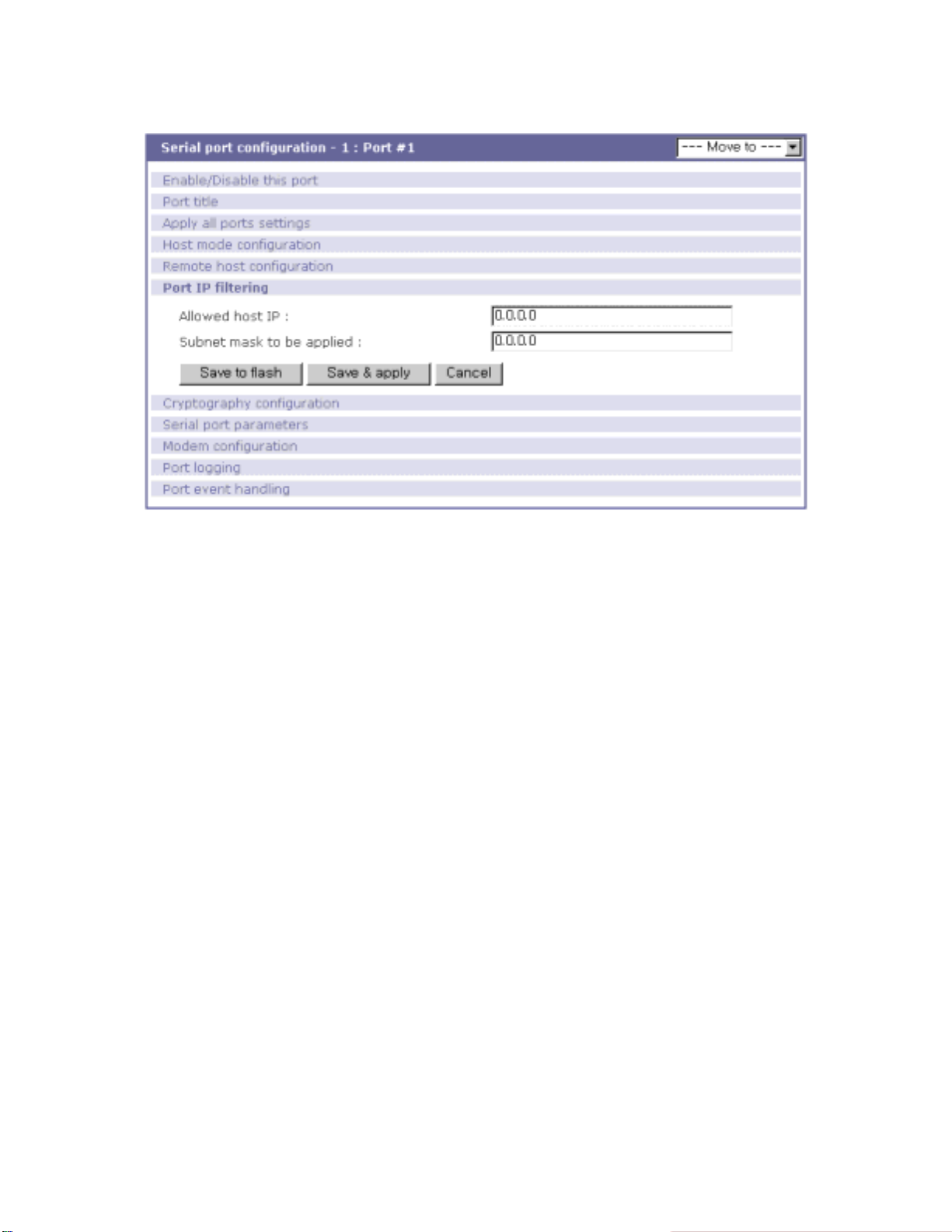
Figure 4-9 Port IP filtering for serial ports
4.2.7. Cry ptography configuration
The STS Series su pports encrypted sessio ns for only TCP mode including mod em emulation mode
(not UDP mode).
4.2.7.1. Secure Sockets Layer(SSL) and Transport Layer Security(TLS) cryptography method
By setting the cryptography method as one of SSLv2, SSLv3, SSLv3 rollback to v2 or TLSv1, the STS
Series can communicate with other device supporting SSL/TLS cryptography method in encrypted
sessions.
SSL was developed by Netscape for use between clients and servers. SSL layers on top of any
transport protocol and can run under application protocols such as HTTP. SSL aims to be secure, fast,
and adaptable to other Web protocols. SSL provides data security for applications that communicate
across networks. SSL is a transport-layer security protocol layered between application protocols and
TCP/IP.
TLS is an updated version of SSL. The protocol is specified in an Internet RFC, developed under
the auspices of t he In te rn et En gin ee ri ng Task Force (IETF). TLS is an ev ol ut io n of SS L and it spec i f ies
a mechanism for falling back to SSL if either client or server does not support the newer protocol, so a
transition to TLS is relatively painless.
To initiate SSL/TLS sessions, exchange of messages called the SSL handshake is required
between two devices (Server and Client). The SSL/TLS protocol uses a combination of public-key and
51
Page 52

symmetric key encryption. Symmetric key encryption is much faster than public-key encryption, but
public-key encryption provides better authentication techniques. The handshake allows the server to
authenticate itself to the client using public-key techniques, and then allows the client and the server to
cooperate in the creation of symmetric keys used for rapid encryption, decryption, and tamper
detection during the session that follows. The details of handshake process step involved can be
summarized as follows:
1. The client sends the server the client's SSL/TLS version number, cipher settings, randomly
generated data, and other information the server needs to communicate with the client using
SSL/TLS.
2. The server sends the client the server's SSL/TLS version number, cipher settings, randomly
generated dat a, and other informat ion the client needs to communicate wit h the server over
SSL/TLS. The server also sends its own certificate and, if the client is requesting a server
resource that requires client authentication, requests the client's certificate.
3. The client uses some of the information sent by the server to authenticate the server. If the
server cannot be authenticated, the user is warned of the problem and informed that an
encrypted and authenticated connection cannot be established. If the server can be
successfully authenticated, the client goes on to next step .
4. Using all data generated in the handshake so far, the client (with the cooperation of the server,
depending on the cipher being used) creates the premaster secret for the session, encrypts it
with the server's public-key (obtained from the server's certificate, sent in step 2), and sends
the encrypted premaster secret to the server. SSL/TLS differ in the way this "shared" master
secret is created
5. If the server has requested client authentication (an optional step in the handshake), the client
also signs another piece of data that is unique to this handshake and known by both the client
and server. In this case the client sends both the signed data and the client's own certificate to
the server along with the encrypted premaster secret.
6. If the server has requested client authentication, the server attempts to authenticate the client.
If the client cannot be authenticated, the session is terminated. if the client can be successfully
authenticated, the server uses its private key to decrypt the premaster secret, then performs a
series of steps (which the client also performs, starting from the same premaster secret) to
generate the master secret.
7. Both the client and the server use the master secret to generate the session keys, which are
symmetric keys used to encrypt and decrypt information exchanged during the SSL/TLS
session and to verify its integrity--that is, to detect any changes in the data between the time it
was sent and the time it is received over the SSL/TLS connection.
8. The client sends a message to the server informing it that future messages from the client will
be encrypted with the session key. It then sends a separate (encrypted) message indicating
52
Page 53

that the client portion of the handshake is finished.
9. The server sends a message to the client informing it that future messages from the server will
be encrypted with the session key. It then sends a separate (encrypted) message indicating
that the server portion of the handshake is finished.
10. The SSL/TLS handshake is now complete, and the SSL/TLS session has begun. The client
and the server use the session keys to encrypt and decrypt the data they send to each other
and to validate its integrity.
Plain
Text
Cipher
Text
Client
Client Hello
Certificate
ClientKeyExchange
CertificateVerify
ChangeCiperSpec
Handshake
Finished
Application Data
Server
Server Hello
Certificate
ServerKeyExchange
CertificateRequest
ServerHelloDone
ChangeCiperSpec
Application Data
Figure 4-10 Typical SSL/TLS Handshake Proc ess
The STS Series can act as a SSL/TLS server or as a SSL/TLS client depending on status of TCP
mode. If TCP connection with SSL/TLS is initiated from remote host first, STS Series acts as a
SSL/TLS server during the SSL handshake process. On the contrary, if TCP connection with SSL/TLS
is initiat ed from serial port of STS Series firs t, STS Series acts as a SSL/TLS client dur ing the SSL
handshake process.
When user uses SSL/TLS cryptography method, user can configure following parameters.
Enable/Disable cipher suites
A cipher suite is an object that sp ecifies the as ymmetric , symmetric and hash algorit hms that are
used to secure an SSL/TLS connection. The asymmetric algorithm is used to verify the identity of
the server (and optionally, that of the client) and to securely exchange secret key information. The
53
Page 54

symmetric algorithm is used to encrypt the bulk of data transmitted across the SSL/TLS
connection. The hash algorithm is used to protect transmitted data against modification during
transmiss ion. T he leng th of the ke ys used in bot h the s ymmet ric an d asymm etri c alg orith ms mus t
also be specified.
When a client makes an SSL/TLS connection to a server, it sends a list of th e cipher suites
that it is capable of and willing to use. The server compares this list with its own supported cipher
suites and chooses the first cipher suite proposed by the client that it is capable of and willing to
use. Both the c li e nt and server then use this cipher suite to secure the connection.
Choice of cipher suite(s) depends on environment and security requirements. The RSAbased cipher suites are the most widely used and may also give some advantages in terms of
speed.
The STS Series support various cipher suites and user can select each cipher suite by
enabling or disabling corresponding cipher suite.
Verify client (server mode only)
If user selects Verify clie nt option as Yes, STS Series will request the client's certificate while in
SSL handshaking process (Step 2). On the contrary, if user selects Verify client option as No, STS
Series does not request the client's certificate while in SSL handshaking process (Step 2).
Verify certificate chain depth
A certificate chain is a sequence of certificates, where each certificate in the chain is signed by
the subsequent certificate. The purpose of certificate chain is to establish a chain of trust from a
its own(peer) certificate to a trusted CA certificate. The CA vouches for the identity in the peer
certificate by signing it. If the CA is one that user trusts (indicated by the presence of a copy of the
CA certificate in user’s root certificate directory), this implies user can trust the signed peer
certific ate as well. In STS Series, user c an restrict nu mber of cert ificate chai n depth so that STS
Series does not search a trust ed CA certificate infinitely in a certificate c hain.
Check the certificate CN
If user selects Check the certificate CN option as Yes, STS Series will check whether the host
name is matched with Common Name(CN) in the certificate, and if they do not matched, STS
Series will close connection request to the remote host. On the contrary, if user selects Check the
certificate CN option as No, STS Series does not check whether the host name is matched with
Common Name(CN) in the certificate.
STS Series checks Common Name(CN) only if it acts as SSL/TLS client.
54
Page 55
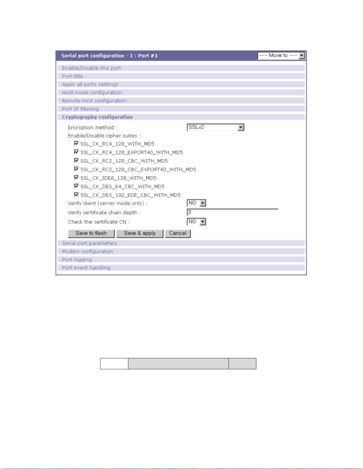
Figure 4-11 Cryptography configuration
4.2.7.2. 3DES cryptography method
By setting t he cryptography meth od a s 3DES, the STS Series can communicate with other STS Series
device or HelloDevice Pro Series in 3DES(168 bits) encrypted sessions.
Figure 4.12 shows record format of 3DES packet where meanings of each field are as follows,
Length Data Padding
Figure 4-12 Record Format of 3DES packet
Length
The length is 8-bits number. The length is the length of content (data and padding). 3DES is a 64bit block cipher algorithm, and then the length must be a multiple of 8(64/8).
55
Page 56

Padding
The padding is a standard block cipher. The pad value is the total number of pad bytes in the
padding(1~8).
In 3DES algorithm in STS Series, key and initial vector, which are used in generating encrypted data
packet, is derived from key block. And key block is generated by using user configured key string.
Figure 4-13 shows key derivation process.
Key Block(32-byte)
Key (24-byte) IV(8-byte)
Figure 4-13 Key derivation
The key block is defined as:
Key_Block = MD5(KEY_STRING) + MD5(MD5(KEY_STRING)+KEY_STRING)
= (16 bytes) + (16 bytes)
Key = first 24bytes of Key Block
IV(Initial Vector) = last 8 bytes of Key block
4.2.7.3. RC4 cryptography method
By setting the cryptography method as RC4, the STS Series can communicate with other STS Series
device in RC4 encrypted sessions. In RC4 encryption mode, STS Series will encrypt/decrypt all the
TCP stream with the user configured key string, and there is no header and no padding. RC4 is faster
than 3DES.
4.2.8. Serial port parameters
To connect the serial device to the STS Series serial port, the serial port parameters of the STS Series
should match exactly to that of the serial devi ce attached. The serial port parameters ar e required to
match this serial communication. The parameters required for the serial communication are: UART
type, baud rate, data bits, parity, stop bits, flow control DTR/DSR behavior and inter-character timeout.
First of all, the STS Series and the serial device must agree on the serial communication type,
56
Page 57
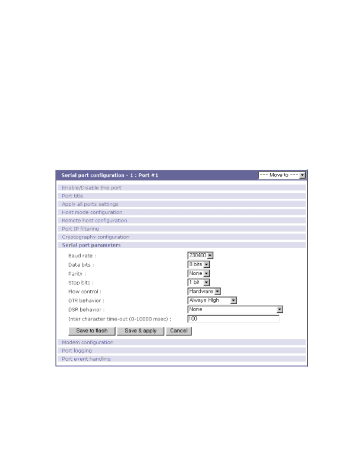
which is RS232 mode. For more information about pin out of serial port and wiring diagram, please
refer to Appendix 1 Connections section.
Baud rate
The valid baud rate for the STS Series is as follows:
75, 150, 200, 300, 600, 1200, 2400, 4800, 9600, 14400, 19200, 38400, 57600, 115200, and
230400
The factory default setting is 9600.
Data bits
Data bits can be between 7 bits and 8 bits. The factory default setting is 8 bits.
Parity
Parity can be
none, even
Figure 4-14 U ART configuration
or
. The factory default setting is none.
odd
57
Page 58

Stop bits
Stop bits can be between 1 bit and 2 bits. The factory default setting is 1 bit.
Flow control
The factory default setting of the flow control is None. Software Flow Co ntrol using XON/X OFF
and hardware flow control using RTS/CTS are supported by the STS Series.
Software flow control method controls data communication flow by sending special characters
XON/XOFF(0x11/0x13) between two connected devices. And hardware flow control method
controls data communication flow by sending signals back and forth between two connected
devices.
Note:
Flow control is supported only in RS232 mode. RS422 and RS485 mode do not support any kind
of flow control method in hardware or software.
DTR/DSR behavior
The purpose of the DTR/DSR pin is to emulate modem signal control or to control TCP
connection state by using serial port signal. The DTR is a write-only output signal, whereas the
DSR is a read-only input signal in the STS Series side.
The DTR output behavior can be set to one of three types: always high, always low or high
when open. If the DTR behavior is set to high when open, the state of the DTR pin will be
maintained high if the TCP connection is established.
The DSR input behavior can be set to one of two types: none or allow TCP connection only by
high. If user sets the DSR input behavior as Allow TCP connection only by HIGH, TCP connection
to remote host f rom STS Series is made on ly when the DSR status is changed from lo w to high.
And TCP connection to remote host is disconnected when the DSR status is changed from high to
low. And also STS Series accepts TCP connection from the remote host only when the DSR status
is high. In case of UDP mode, STS Series receives UDP data from the remote host only when the
DSR status is high.
In modem emulation mode, the connection to the remote host will be disconnected regardless of
the current DSR input behavior option if the DSR status goes to low.
Note:
DTR/DSR behavior menu will not be shown when the modem is enabled.
Inter-character timeout
This parameter defines the interval that the STS Series fetches the overall serial data from its
internal buffer. If there is incoming data through the serial port, the STS Series stores data into
58
Page 59

the internal buffer. The STS Series transfers data stored in the buffer via TCP/IP, only if the
internal buffer is full or if the inter-character time interval reaches to the time specified as inter-
character timeout. If inter-character timeout is set as 0, then data stored in the internal buffer will
be transferred immediately without any delay.
Optimal inter -character ti meout would be dif ferent accordi ng to your applic ation but at leas t it
must be larger than one character interval within specified baud rate. For example, assume that
the serial port is set to 1200 bps, 8 Data bits, 1 stop bit, and no parity. In this case, the total
number of bits to send a character is 10 bits and the time required to transfer one character is
10 (bits) / 1200 (bits/s) * 1000 (ms/s) = 8.3 ms.
Therefore, you have to set inter-character timeout to be larger than 8.3 ms. The inter-character
timeout is specified in milliseconds.
If users want to send the series of characters into a packet, serial device attached to the STS
Series should send characters without time delay larger than inter-character timeout between
characters and the total length of data must be smaller than or equal to the STS Series internal
buffer size. The serial communication buffer size of STS Series is 256 bytes.
4.2.9. Modem configuration
The STS Series supports direct modem connection to the serial port of it. When user wants to connect
modem to a serial port, he must configure Modem init-string and DCD behavior on modem
configuration page. The STS Series supports modem connection only when host mode is set as TCP
mode.
Enable/Disable modem
By enabling this menu, user can attach a modem directly to the serial port of STS Series. If this
parameter is enabled, STS Series considers this port will be used for modem use exclusively.
Modem init-string
User can specify modem initialization string for his modem in Modem init-string parameter. When
a serial port is set as modem mode by setting Enable/Disable modem parameter as Enabled,
STS Series sends modem initialization string to the serial port whenever rising edge of DTR pin is
detected or parameter related with serial port configuration is changed.
DCD behavior
If DCD behavior is set as Allow TCP connection only by HIGH, STS Series permits a c onnection
from the remote host only when the DCD status of serial port is high. This feature is useful when
user want to use a serial port only for dial-in modem mode. In this case, if there is no connection
59
Page 60
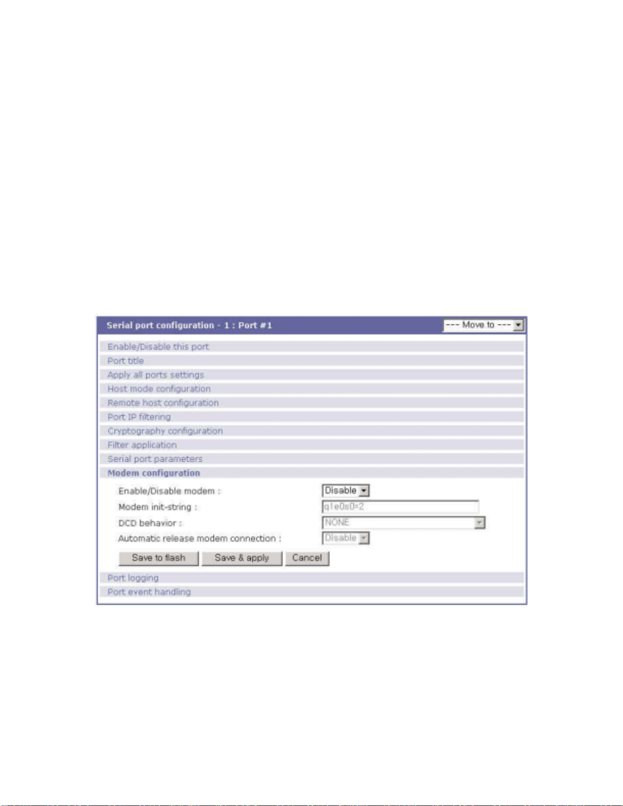
through modem already, STS Series dose not permit TCP side connection.
Automatic release modem connection
If Automatic release modem connection is set as Enable, modem connection will be closed by
STS Series if all TCP connections are closed once at least one TCP connection is opened. If this
option is set as Disable, modem connection will not be closed by STS series even if all TCP
connections are closed. Please note that actual phone line connection will be closed if one of
modems closes connection, regardless of this option. That is, this option can be used for STS
Series to disconnect modem connection by itself when all TCP connections are closed.
If user want to use dial-out function, he should set DCD behavior as None because he must
be able to access modem connected to a serial port to send dial out command to the modem first.
Figure 4-15 Modem configuration
4.2.10. Port Logging
With the port logging feature, the data sent through the serial port is stored to MEMORY, an ATA/IDE
fixed disk c ard, a SYSLOG server or a mounting point on an NFS server.
60
Page 61

Enable/disable port logging
This parameter defines whether to enable or disable the port-logging feature. The factory default
setting is [disabled].
Port log storage location
The port log data can be stored to the STS Series internal memory, an ATA/IDE fixed disk card
inserted in PCMCIA slot, the mounting point on an NFS server or the SYSLOG server. If the
internal memory is used to store port log data, the port log data will be cleared when the STS
Series is turned off. To preserve the serial port log data, set the storage location to be the ATA/IDE
fixed disk card, SYSLOG server or NFS server. To do this, the user must configure the
corresponding media in advance. Unless the media is properly set up, the user will not be able to
select a storage location from the interface.
Port log buffer size
This parameter defines the maximum amount of port log data to be logged. When using internal
memory to store the log data, the total size of the port buffer cannot exceed 3200 Kbytes (i.e. sum
of all port buffer size of each serial port should be smaller than or equal to 3200 Kbytes). The
factory default setting is 4 Kbytes.
When using an ATA/IDE fixed disk card to store log data, the maximum port buffer size is
dependent upon the card capacity.
When using an NFS server to store log data, the maximum port buffer size is unlimited. The
user should configure the NFS server to ensure that the port logging system works properly.
When using the SYSLOG server to store log data, the user cannot set the port log buffer size.
61
Page 62
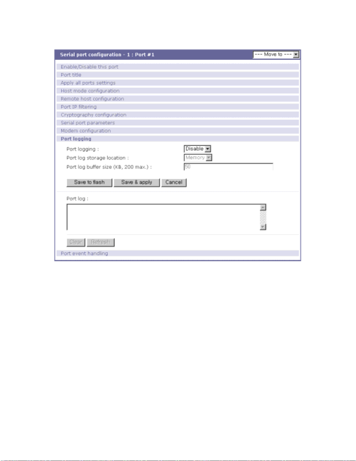
Figure 4-16 Port logging configuration
4.2.11. Port event handling configurations
The STS Series provides a user for a means of monitoring or reacting to data from serial device
attached to a serial port of it through Port event handling configuration. Namely, user can define
keywords for each serial port that will trigger the email/SNMP notification or command sent to the
serial port directly on Port event handling configuration. And this will enable the user to monitor the
data from the attached device or to manage/control a device attached serial port directly when predefined keywords are detected. At the same time, the status of the connection between the STS
Series and the serial device and the status of the TCP connection between the STS Series and
remote hosts could be monitored and managed in the same way of the port keywords as well.
Each reaction can be configured individually upon each keyword. Reaction can be an email
delivery, SNMP trap sending, command sending or either combination of all reactions.
Port event handling
62
Page 63

If the user wants to enable port event handling feature, set Port event handling as enable. . This is
a global parameter so if this feature is disabled, the STS Series does not take any actions on port
events.
Notification interval
To prevent STS Series from being trapped in handling port event, there is a Notification interval
parameter. STS Series will send notification email or SNMP trap every Notification interval ev en it
detect predefined keyword within Notification interval. The smaller value of this parameter will
result in immediate response for predefined keyword and heavy usage of system resources. The
largest value accepted by user is recommended to prevent system resource usage minimization.
Email notification
This parameter enables or disables Email notification feature of STS Series. When STS Series
sends Email notification, it used SMTP server configured in SMTP server configuration. If the
SMTP server is not configured correctly or disabled, Email feature gets disabled also. For details
of SMTP server configurations and descriptions, please refer to section 3.4 SMTP Configuration.
Title of Email
This parameter set Title of Email that will be sent by STS Series when pre-defined keyword is
detected.
Recipient's E m ail address
This parameter set mail recipient who will receive notification mail when pre-defined keyword is
detected.
SNMP notification
This parameter enables or disables SNMP notification feature of STS Series.
Title of SNMP trap
This parameter set Title of SNMP trap that will be sent by STS Series when pre-defined keyword
is detected.
SNMP trap receiver IP
This parameter set IP address of SNMP trap receiver that will receive SNMP trap notification
when pre-defined keyword is detected.
63
Page 64
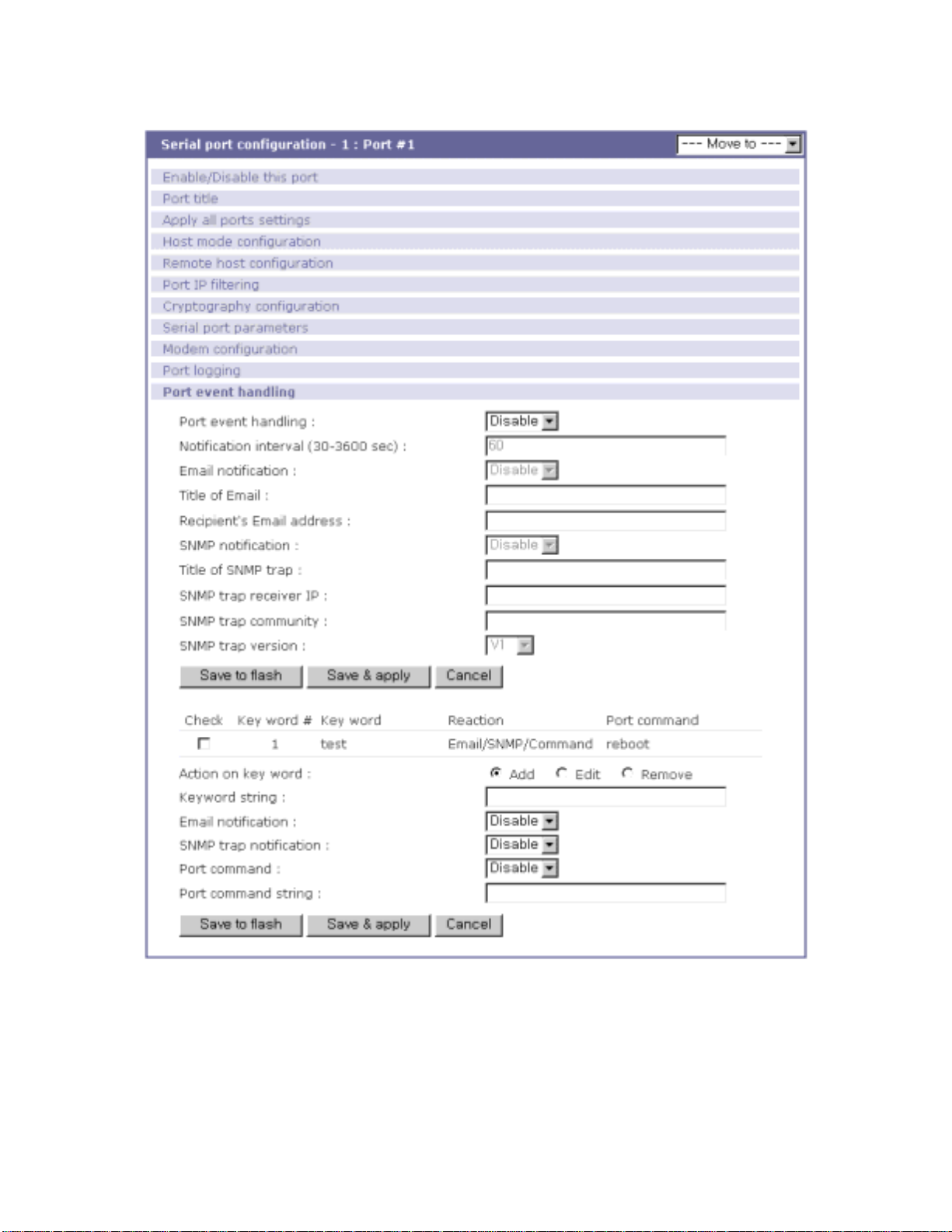
Figure 4-17 Port event handling configurations
SNMP trap community
This parameter set a community that will be included in SNMP trap message when pre-defined
keyword is detected.
64
Page 65

SNMP trap version
This parameter set a version of SNMP trap, which will be sent when pre-defined keyword is
detected.
[Status event edit]
Device connection/disconnection
Fill in the check boxes of the preferred actions that are to be taken on the event of serial device
connection or disconnection.
TCP connection/disconnection
Fill in the check boxes of the preferred actions that are to be taken on the event of TCP
connection or disconnection from remote hosts.
[Keyword list edit]
Action on key word
User can select “Add” or “Remove” for the action on keyword selected.
Keyword string
User can specify any word, which he/she wants to set as a keyword.
Email notification
User can select enable or disable for the Email notification action on keyword selected.
SNMP trap notification
User can select enable or disable for the SNMP trap notification action on keyword selected.
Port command
User can select enable or disable for the port command action on keyword selected.
Port command string
STS Series supports direct reaction to a device attached to serial port when pre-defined keyword
is detected. User can specify command or string, which will be sent to a serial port on this menu.
65
Page 66
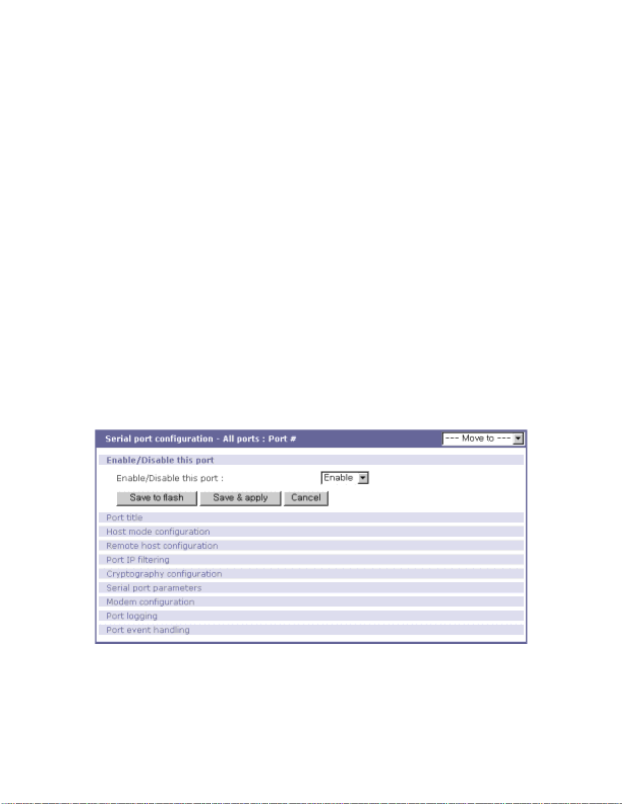
4.3. All Port Configurations
If modifications are being made to all serial ports are similar or the same, changes can be made to the
serial port configuration for all serial ports simultaneously. With the
all port configuration
function, the
configuration will be applied to all the serial ports; unless an individual ports “apply all port setting”
option is disabled.
“All port configuration” parameters can be grouped into the following groups:
1. Port enable/disable
2. Port title
3. Host mode
4. Remote host configuration
5. Port IP filtering
6. Cryptography configuration (Only valid and visible if host mode set to TCP or Modem
Emulation mode)
7. Serial port parameters
8. Modem configuration (Only valid and visible if host mode set to TCP mode)
9. Port logging
10. Port event handling
Figure 4-18 All port configuration
Port enable/disable
This parameter enables or disables port function.
Port title
If this parameter is set with a certain string, the port title of each serial port will be set with a
66
Page 67

combination of this string and the port number. For example, if the port title is set with “my
server”, the port title of port 1 will be set with “my server #1”, the port title of port#2 will be “my
server #2”, and so on.
Host mode
If the host mode is set to TCP or UDP mode, the listening port number of each serial port will be
set with the following equation:
(listening port number + serial port number - 1)
Other parameters of each serial port will be set as the s ame value set in as “all port configuration”.
Remote host configuration, Port IP filtering, Cryptography configuration, Serial port
parameters, Modem configuration, Port logging, Port event handling
For the parameters of the groups above, the values set in an “all port configuration” will be set
identically for all of the serial ports.
67
Page 68
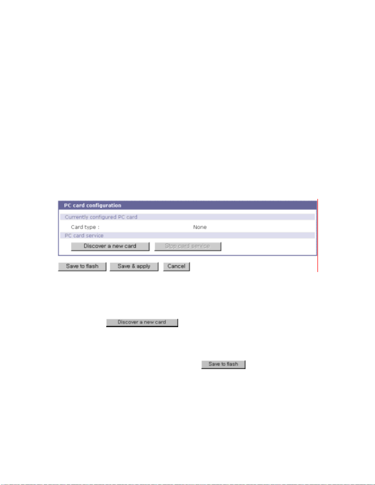
5. PC Card Configuration
The STS Series has one extra PC card slot for increased expandability. It supports four types of PC
cards:
- Wireless LAN card
- Modem card
- ATA/IDE fixed disk card
The user can allow access via another network connection with either a LAN or wireless LAN card.
The ATA/IDE fixed disk card allows the user the ability to store and carry system and serial port log
data. Using the card slot for a modem card allows the user out-of-band access to the STS Series
without a serial port to connect to an external modem.
Figure 5-1 Initial PC card configuration menu screen
To use the PC card slot, the users must complete the following steps.
Step 1. Insert the PC card into the PC card slot.
Step 2. Select
Step 3. The STS Series will use its plug and play functionality to discover the card type. It will
then display the configuration menu screens. The user can now set card’s operation
parameters.
Step 4. Save the configuration settings by selecting
Step 5. Select [
If STS Series fail s to disc over t he PC card, the foll owing er ror mes sage will be dis playe d on the me nu
screen.
Apply changes
] from the m enu to apply the newly configured settings.
on the PC card configuration menu.
.
68
Page 69

Figure 5-2 Failure to detect error message
Refer to Appendix B.PC Card supported by STS Series to view a list of PC cards support by the STS
Series.
To stop or remove the PC card, user must complete the following steps.
Step 1. Select [(
Step 2. Save the configuration changes by selecting [
Step 3. Apply changes by selecting [Apply changes] from the menu.
Step 4. Remove the PC card from the PC card slot.
Removing the PC card from the slot without following the above instructions may cause a
Note:
system malfunction.
Ban- show the actual button)
Stop card service].
Save to flash
].
5.1. LAN Card Configuration
A LAN card will create two network interfaces and two IP addresses. The users can assign a valid IP
address to each serial port. The IP address must be valid in the STS Series built-in network interface
or the environment of STS Series PC card LAN interface environment.
69
Page 70
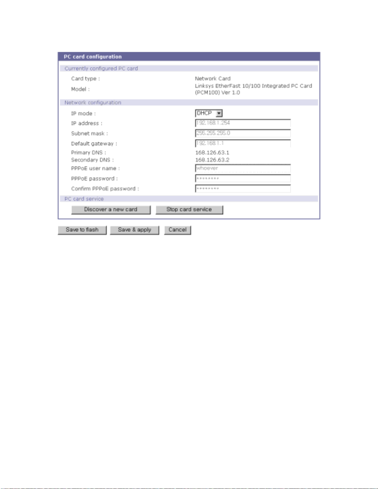
Figure 5-3 PC LAN card configuration
The user must manually select PC LAN card as the card type and set the primary and secondary DNS
servers when configuring a PC LAN card. All other configuration steps are the same as detailed in
Section 3.1 IP Configuration.
Refer to Appendix B.PC Card supported by STS Series to view a list of LAN PC cards supported
by the STS Series.
5.2. Wireless LAN Card Configuration
A wireless LAN card will result in two network interfaces and two IP addresses. The user can assign a
valid IP address to each serial port. The IP address must valid in the STS Series built-in network
interface or in the wireless LAN interface environment.
70
Page 71
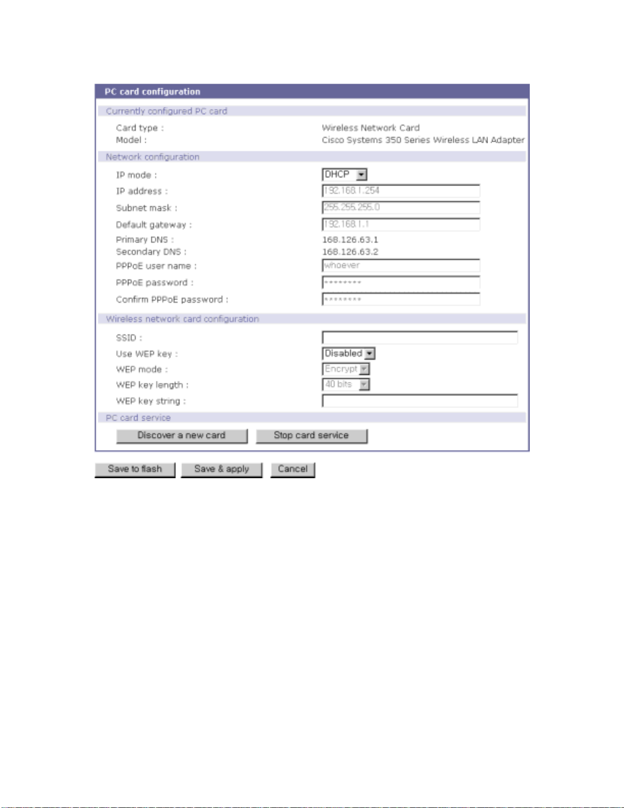
Figure 5-4 PC wireless LAN card configuration
The user must manually select WIRELESS LAN CARD as the card type and set the primary and
secondary DNS servers when configuring a PC LAN card. All other configuration steps are the same
as detailed in Section 3.1 IP Configuration.
The STS Series supports SSID(Service Set Identifier) and WEP(Wired Equivalent Privacy) key
features for the wireless LAN configuration. The user may configure the SSID to specify an AP
(Access Point). The user may also configure the WEP mode as either encrypted or shared. The WEP
key length must be either 40 or 128 bits. The 40-bit WEP key length requires the user to enter 5
hexadecimal code sets without colons (:). The 128 bits WEP key length requires the user to enter 13
hexadecimal code sets without colons (:).
For example, to use the 128 bits WEP key length option, the user must enter 13 hexadecimal
code sets as follows:
000F25E4C2000F25E4C2000F24
71
Page 72
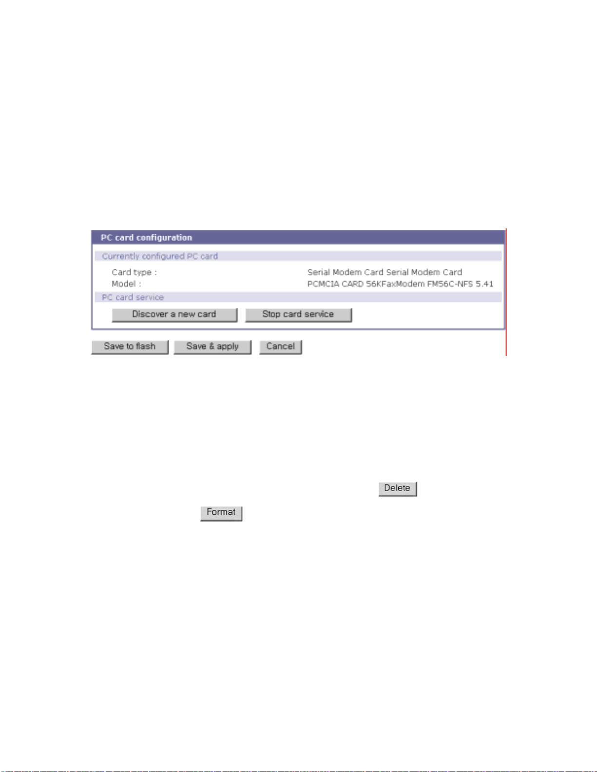
Refer to Appendix B.PC Card supported by STS Series to view a list of wireless LAN cards supported
by the STS Series.
5.3. Serial Modem Card Configuration
Using the extr a PC card slot as a modem will allow the user o n-line access wit hout tying up a seria l
port with an external modem. Most 56Kbps PC serial modem cards are compatible with the PC card
slot. A complete catalog of modem cards supported by the STS Series is list ed in Appendix B.
Figure 5-5 PC serial modem card configuration
5.4. ATA/IDE Fixed Disk Card Configuration
The user must configure the total data size required to use the PC ATA/IDE fixed disk card to store the
system and ser ial p ort log. The ST S Se ries will a utom atic all y loca te t he tot al st orag e siz e and t he di sk
space available on the disk.
The user may delete all the files currently on the card by selecting
The user may select
file systems for the disk card.
VFAT
The user may store or retrieve the STS Series configuration files to/from the disk by
exporting/importing the STS Series configuration.
to format the card. The STS Series supports both EXT2 and
.
72
Page 73
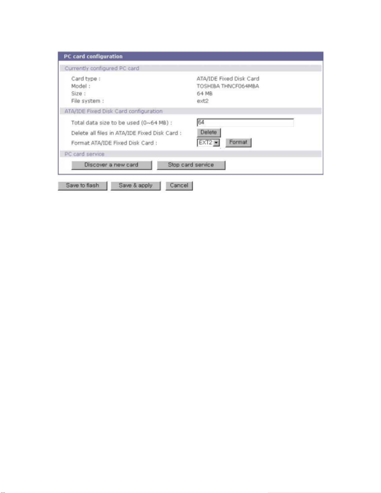
Figure 5-6 PC ATA/IDE fixed disk card conf igu r at i o n
73
Page 74
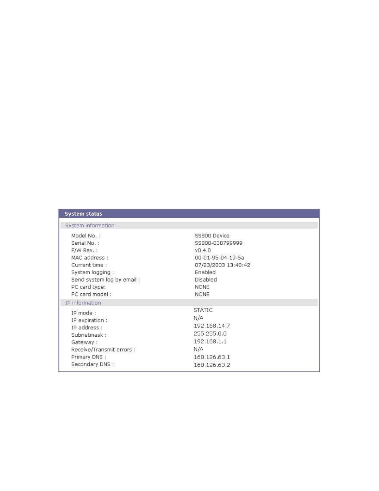
6. System Administration
The STS Series display the system status and the log data via a Status Display Screen. This screen is
to be used for management purposes. System status data includes the model name, serial number,
firmware version and the network configuration of the STS Series. The STS Series can also be
configured to deliver log data automatically via email to a specified recipient with the system-logging
feature.
The users can configure the STS Series’s device name, date and time settings, and reload factory
default settings in this menu group. The users can also upgrade the firmware of the STS Series using
the web interface, remote consoles or serial console.
6.1. System Status
Figure 6-1 System status display
6.2. System Logging
The STS Series provid es both t he syst em loggi ng fe ature a nd the s ystem log status display. The user
may configure the STS Series to enable or disable the system logging process, the system log buffer
size, as well as select the log storage location.
74
Page 75

System log storage location
The system log c an be stor ed in th e STS Series internal memory, the ATA/IDE fixed disk card
inserted in PCMCIA slot, the
mounting point on an NFS server
or the
SYSLOG server
internal memory is used to store system log data, the log data will be cleared when the STS
Series is turned off. To preserve the system log data, set the storage location to be the ATA/IDE
fixed disk card, SYSLOG server or NFS server. To do this, the user must configure the
corresponding media in advance. Unless the media is properly set up, the user will not be able to
select a storage location from the interface.
System log buffer size
This parameter defines the maximum amount of system log data that can be logged. When using
internal memory to store data, the total size of the system log cannot exceed 300 Kbytes.
When using an ATA/IDE fixed disk card to store log data, the maximum buffer size is
dependent upon the card capacity.
When using an NFS server to store logs data, the maximum buffer size is unlimited. The user
should configure the NFS server to ensure that the port logging system works properly.
When using the SYSLOG server to store log data, the user cannot set the buffer size.
The STS Series can also be configured to send log data automatically if the number of logs
unsent reaches a pre-defined number. If enabled, the user must set parameters to initiate the
creation of a email. These parameters would include the number of logs required to trigger an
email, the recipient email address, etc. Figure 6-2 shows the configuration and system log view
screen.
. If the
75
Page 76
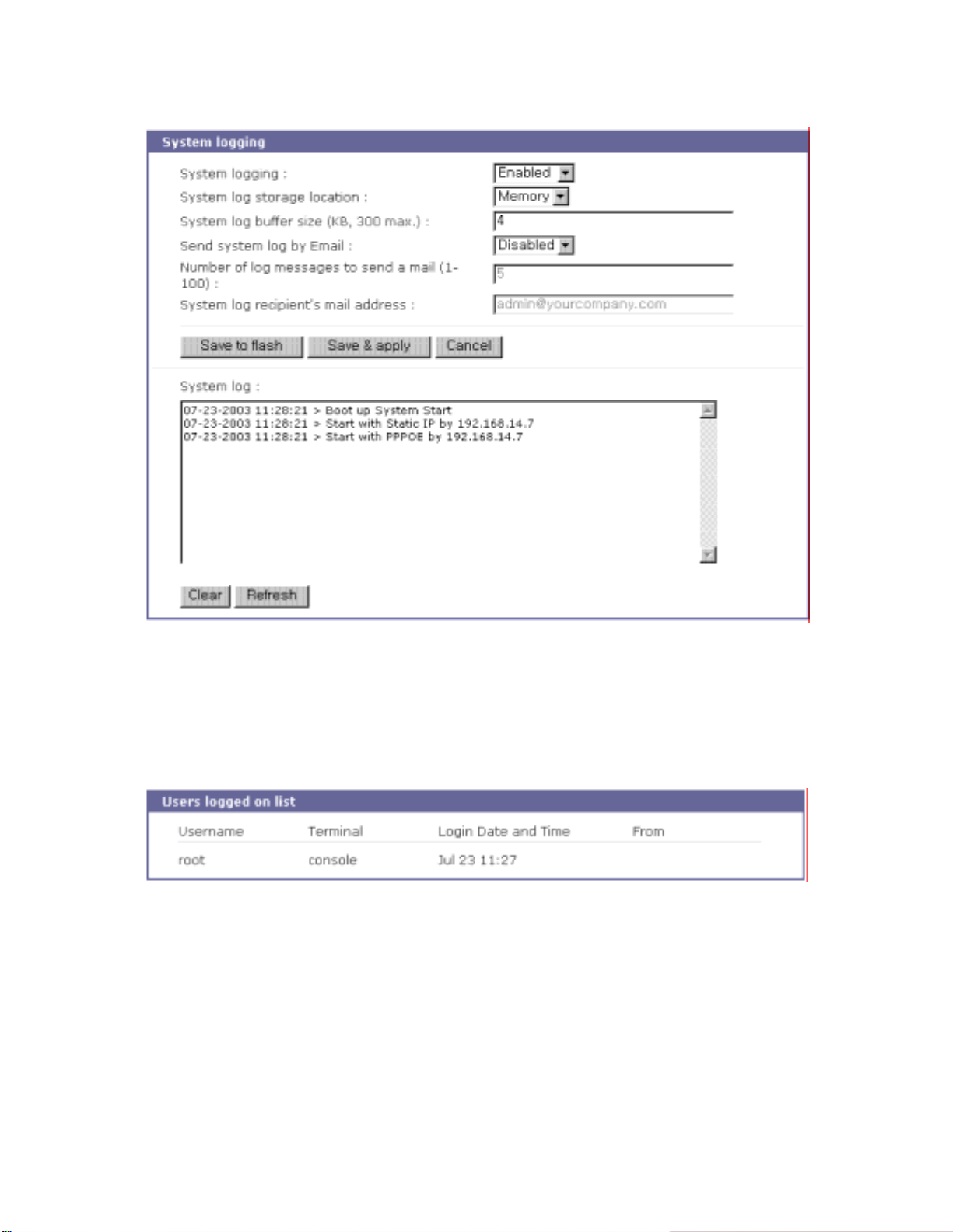
Figure 6-2 System log configuration and view
6.3. User Logged on List
This function allows a user to view current and historical user activity on the shell of STS Series.
Figure 6-3 User logged on list
The list displays the following information for users who have logged into the system:
User name
Terminal type for the session
Time connected
IP address of the remote host
Note: Users access via the web will not appear on the list. Connections are not always made using
HTTP/HTTPS protocol.
76
Page 77
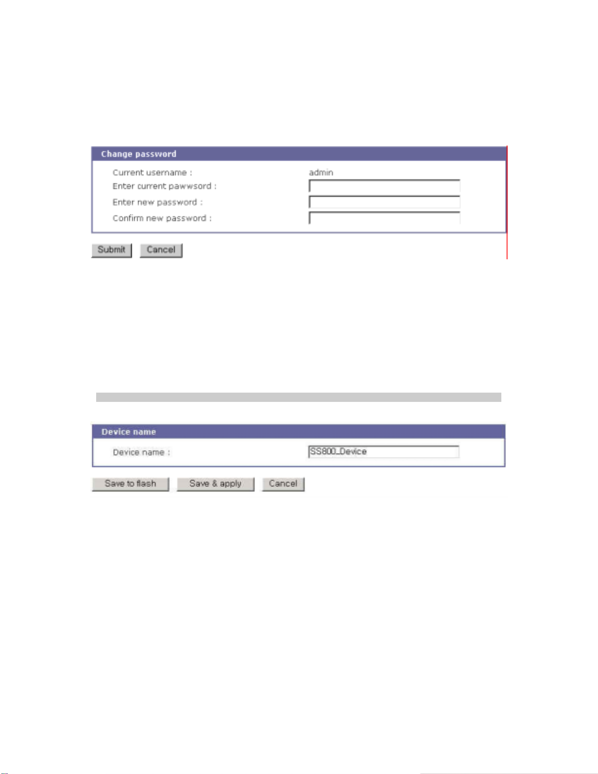
6.4. Change Password
The password for the administrative users of STS Series can be changed.
Figure 6-4 Changing the password
6.5. Device Name Configuration
The STS Series has its own name for administrative purposes. Figure 6-5 shows the device name
configuration screen. When user changes Device name, hostname of STS series shall be changed
and then prompt on CLI also shall be changed to the corresponding one as follows,
root@STS800_Device:~#
Figure 6-5 Device name configuration
Please note that user cannot set space character as one of device name. And If user sets blank
as Device name then hostname is set as IP address of STS series automatically.
And also the device name is utilized for management program, HelloDevice Manager.
6.6. Date and Time Settings
The STS Series maintains current date and time information. The STS Series clock and calendar
settings are backed up by internal battery power. The user can change the current date and time, as
shown in Figure 6-6.
There are two date and time settings. The first is to use the NTP server to maintain the date and
77
Page 78
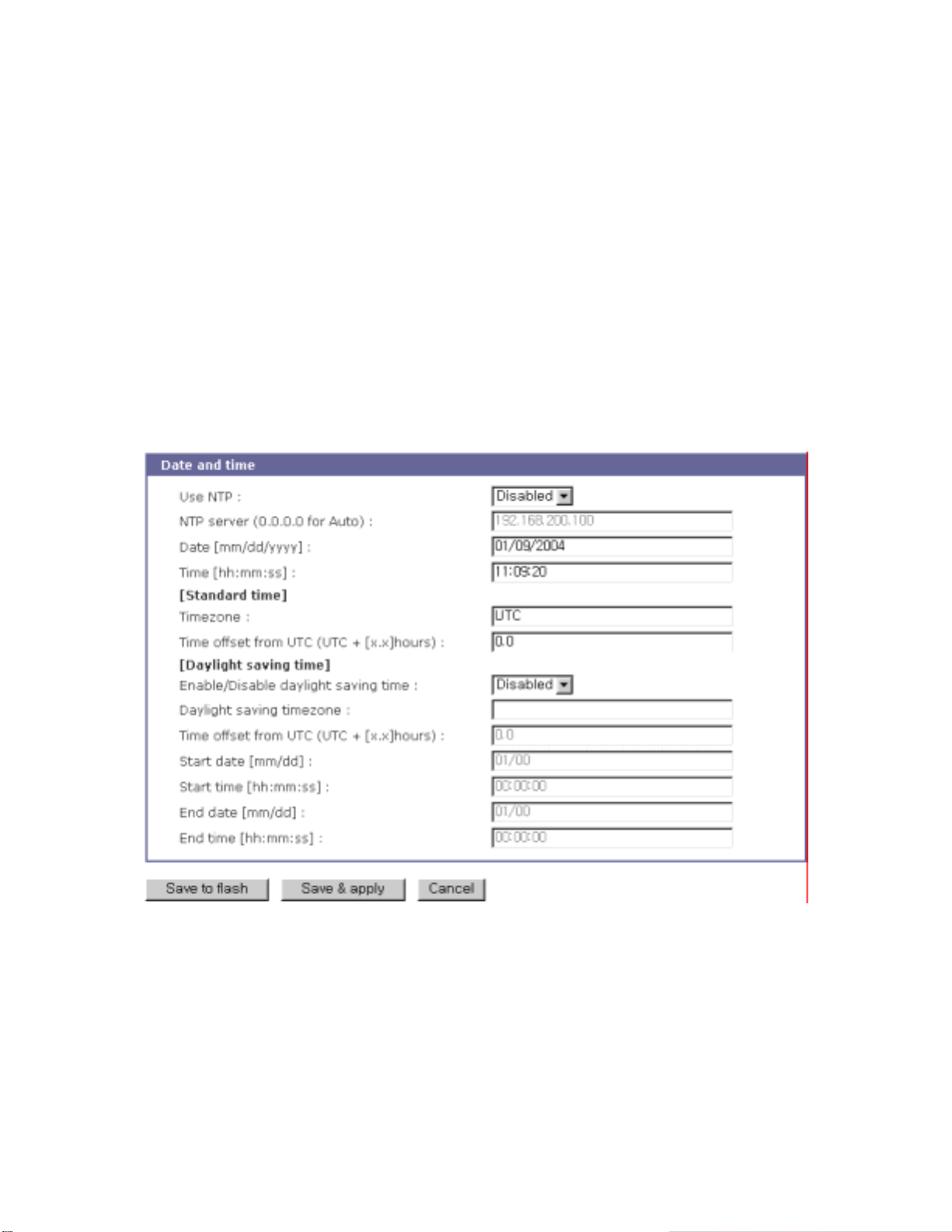
time settings. If the NTP feature is enabled, the STS Series will obtain the date and time information
from the NTP server at each re boot. If the NTP s erver is set to 0. 0.0.0, the STS S eries will use the
default NTP servers. In this case, the STS Series should be connected from the network to the
Internet. The user may also need to set the time offset from UTC depending on the users’ location.
The second method is to set date and time manually without using the NTP server. This will allow
the date and time information to be kept maintained by the internal battery backup.
The users may also need to set the timezone and the time offset from UTC depending on the
users’ locat ion t o set syst em da te an d tim e exac tl y. I f the user u ses da yli ght sav ing t ime , the user ma y
need to set the daylight saving time properties such as the daylight saving timezone, the time offset
from UTC, start data and time, end date and time. It allows the STS Series to calculate the exact
system time.
Figure 6-6 Date and time configuration
6.7. Configuration management
The user may export the current configurations to a file at such locations as CF card, NFS server, user
space or local machine and import the exported configurations as current configurations from CF card,
NFS server, user space or local machine.
The user may restore the factory default settings at any time by selecting “Factory default” at
78
Page 79
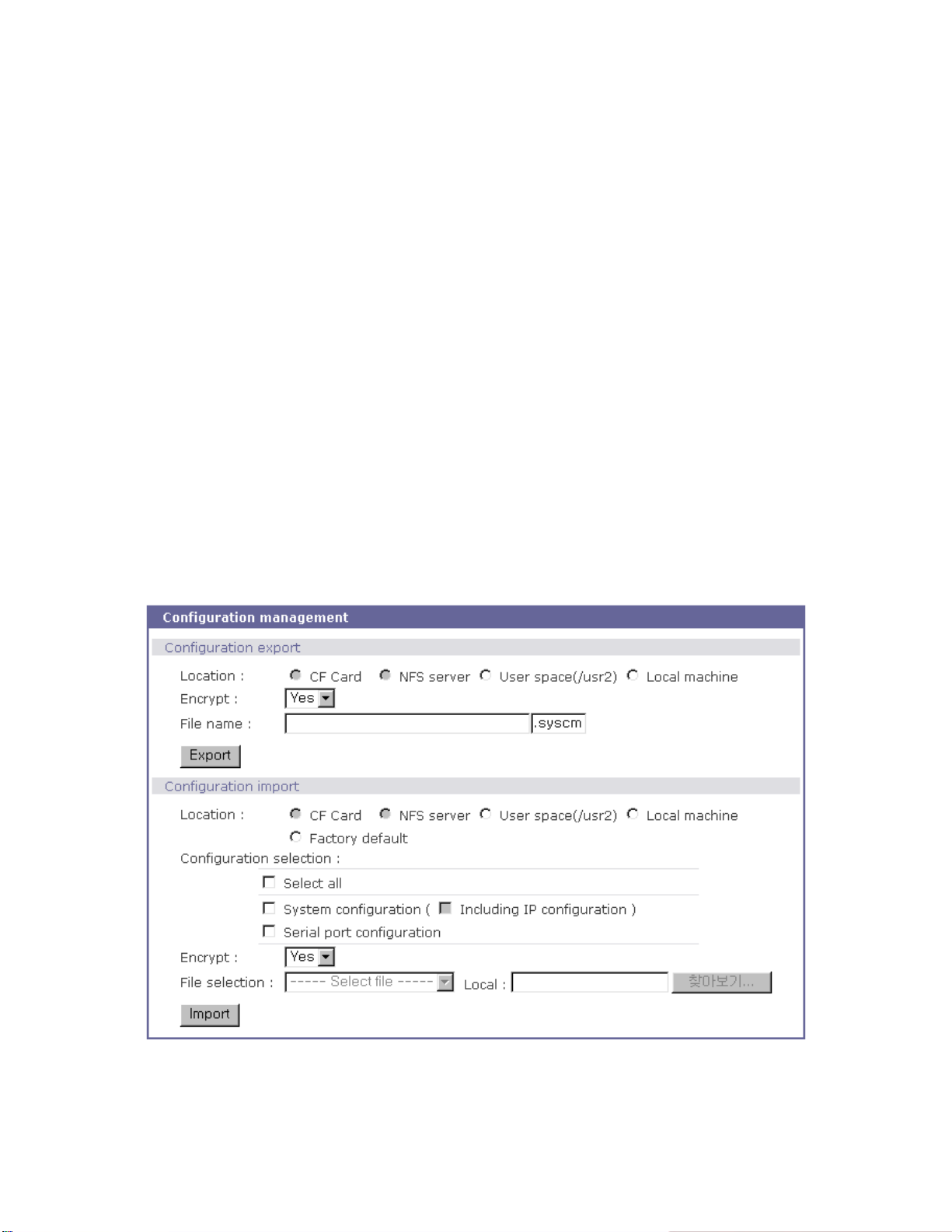
location property at the import part or by pushing the factory default reset switch on the back panel of
the STS Series. Figure 6-7 shows the configuration management screen. The following parameters
should be properly set up to export / import configurations:
Configuration export
Location : Location to export to.
Encrypt : Yes or No.
File name
Configuration import
Location : Location to im port f rom. B y selec ting Factor y default, the user may restore the factory
settings.
Configuration selection :
Determines what kinds of configurations are imported.
Encrypt : Yes or No. If location is Factory default, it has no effects.
File selection : List all the exported files satisfying the encrypting option at the selected location
which is one of CF card, NFS server and user space.
Local :
Helps to browse the exported file at local machine if location is local machine.
Figure 6-7 Configuration management
To export the current configurations, follow this:
79
Page 80
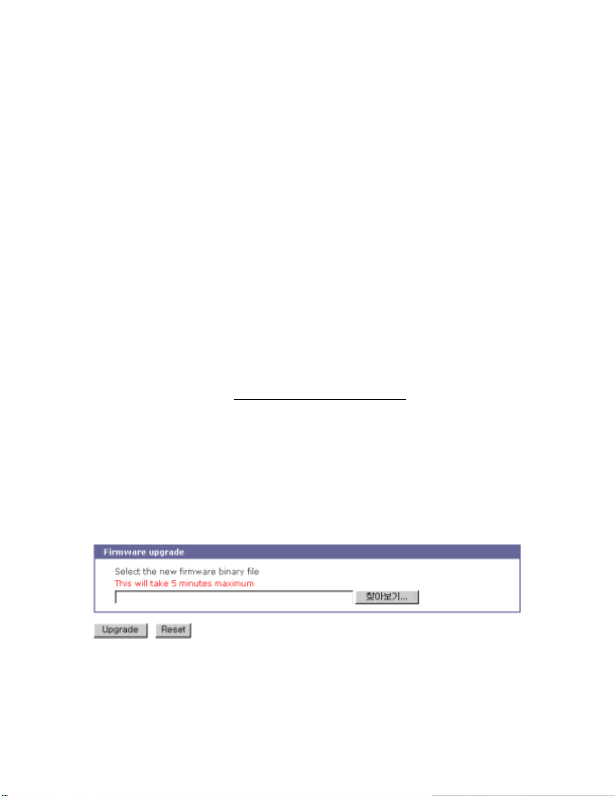
1. Select the location to export to.
2. Select the encrypting option
3. Type the file name.
4. Click the [Export] button.
To import the exported configurations, follow this:
1. Select the location to import from.
2. Select the configurations to import.
3. Select the encrypting option.
4. Select the file to import from the file selection list box if location is not local machine nor
factory default.
5. Select the file to import by clicking browse button if location is local machine.
6. Click the [Import] button.
6.8. Firmware Upgrade
Firmware upgrades are available via serial, remote console or web interface. The latest upgrades are
available on the Sena web site at http://www.s en a.com/support/downloads/
Figure 6-8 shows the firmware upgrade web interface.
To upgrade f irmware via the web:
1. Select the latest firmware binary by clicking browse button.
2. Select and upload the selected version.
3. Once the upgrade has been completed, the system will reboot to apply the changes.
.
Figure 6-8 Firmware upgrade
To use either a remote or serial console to upgrade your firmware, the TELENT/SSH or terminal
emulation program must support Zmodem transfer protocol. After the firmware upgrade, the previous
settings will be reset to the factory default settings, except the IP configuration settings.
80
Page 81

To upgrade firmware via a remote console:
1. Obtain the latest firmware.
2. Connect the terminal emulation program using either TELENT/SSH or a serial console
port.
(TELNET or SSH is recommended since the process of firmware upgrade by serial
console requires extremely long time.)
3. Select from the firmware upgrade menu as shown Figure 6-9.
4. Follow the online directions and transfer the firmware binary file using the Zmodem
protocol as shown in Figure 6-10.
5. Once the upgrade has been completed, the system will reboot to apply the changes
6. If the firmware upgrade fails, the STS Series will display error messages as shown in
Figure 6-11. It will also maintain the current firmware version.
Login : admin
Password : *****
----------------------------------------------------------------------------- Welcome to STS-800 configuration page
Current time: 07/23/2003 15:04:07 F/W REV.: v1.0.0
Serial No.: STS800438349-42944 MAC address: 00-01-95-04-19-5a
IP mode: Static IP IP address: 192.168.14.7
----------------------------------------------------------------------------- Select menu:
1. Network configuration
2. Serial port configuration
3. PC Card configuration
4. System administration
5. Save changes
6. Exit without saving
7. Exit and apply changes
8. Exit and reboot
<Enter> Refresh
---> 4
----------------------------------------------------------------------------- System administration
----------------------------------------------------------------------------- Select menu:
1. System status
2. System logging
3. Device name: STS800 Device
4. Date and time
5. Change password
6. User file upload
7. Reload factory default settings
8. Reload factory default settings except IP settings
9. Firmware upgrade
<ESC> Back, <Enter> Refresh
--->9
Do you want to upgrade firmware? (y/n): y
Transfer firmware by zmodem using your terminal application.
To escape, press Ctrl+X
**B0ff000005b157
Figure 6-9 Firmware upgrade using remote/serial console
81
Page 82
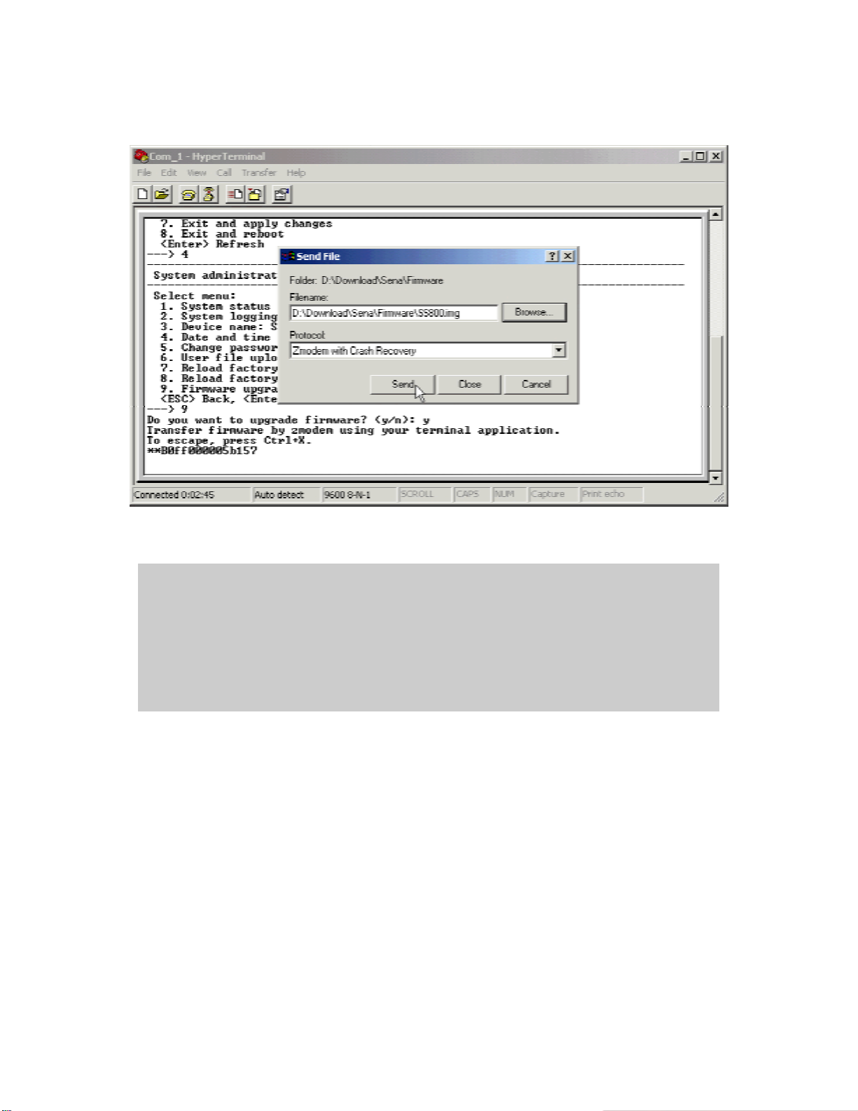
Figure 6-10 Tr a nsfer binary file by Zmodem (HyperTermi n al )
--->9
Do you want to upgrade firmware? (y/n): y
Transfer firmware by zmodem using your terminal application.
To escape, press Ctrl+X
**B0ff000005b157
**B0ff000005b157
**B0ff000005b157
**B0ff000005b157
Firmware upgrade failed !
Now reboot ...
Figure 6-11 Firmware upgrade failure message
82
Page 83

6.9. User File Uploading
User can upload his own file to the STS Series. But file uploading feature is only supported in console
menu. File uploading menu is located under “4. System administration --> 6. User file upload” of
console menu as shown on Figure 6-12.
To upload user file to the STS Series using console menu, user must use a TELNET/SSH or
terminal emulation program which supports Zmodem transfer protocol.
Uploading procedure is similar to firmware upgrade using console menu as follows,
1. Prepare user file to be uploaded.
2. Connect the terminal emulation program using either TELNET/SSH or a serial console
port.
(TELNET or SSH is recommended since the process of firmware upgrade by serial
console. Using a serial console port may take a long time.)
3. Select from the user file upload menu as shown Figure 6-12.
4. Follow the online directions and transfer the user file using the Zmodem protocol as
shown in Figure 6-10.
5. Once the upload has been completed, the system will display success messages as
shown in Figure 6-12.
6. If the upload fails, the STS Series will display error messages as shown in Figure 6-13.
Note :
User file uploading is permitted only under user space (/usr2) directory. For more information about
file system inside STS Series, please refer to 8.2 Flash partition section.
----------------------------------------------------------------------------- Welcome to STS-800 configuration page
Current time : 08/14/2003 11:56:13 F/W REV. : v1.0.0
Serial No. : STS800438349-42944 MAC address : 00-01- 95- 04-d3-03
IP mode : DHCP IP address : 192.168.222.206
----------------------------------------------------------------------------- Select menu:
1. Network configuration
2. Serial port configuration
3. PC Card configuration
4. System administration
5. Save changes
6. Exit without saving
7. Exit and apply changes
8. Exit and reboot
<Enter> Refresh
---> 4
----------------------------------------------------------------------------- System administration
------------------------------------------------------------------------------
83
Page 84

Select menu:
1. System status
2. System logging
3. Device name: STS800 Device
4. Date and time
5. Change password
6. User file upload
7. Reload factory default settings
8. Reload factory default settings except IP settings
9. Firmware upgrade
<ESC> Back, <Enter> Refresh
---> 6
Do you want to upload a file to user space? (y/n): y
Enter a filename: test.txt
The file will be saved as /usr2/test.txt.
Transfer a file by zmodem using your terminal application.
To escape, press Ctrl+X.
**B01ff000005b157
Uploading a file is completed.
Figure 6-12 User file upload menu and success messages
Do you want to upload a file to user space? (y/n): y
Enter a filename: test.txt
The file will be saved as /usr2/test.txt.
Transfer a file by zmodem using your terminal application.
To escape, press Ctrl+X.
**B01ff000005b157
Uploading a file failed.
Figure 6-13 User file upload fail messages
84
Page 85
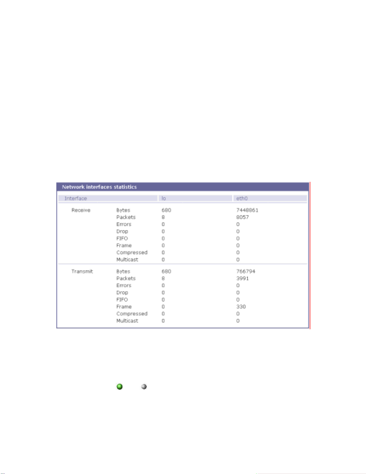
7. System Statistics
The STS Series Web interface provides system statistics menus. The user can use the menus to
access statisti cal data and tabl es stored in the S TS Series memory. N etwork interf aces statist ics and
serial ports statistics display statistical usage of the link layer, lo, eth and serial ports. IP, ICMP, TCP
and UDP statistics display usages of four primary components in the TCP/IP protocol suite.
7.1. Network Interfaces Statistics
Network int erf ac es st ati st ics di spl ay b asi c ne two rk in terf ac es usag e of the S TS S eries , lo and eth0. lo
is a local loop back interface and
is a default network interface of STS Series.
eth0
Figure 7-1 Network interfaces statistics
7.2. Serial Ports Statistics
Serial ports statistics display the usage history of 32 serial ports, baud rate configurations and
each port’s pin status. (
: On : Off )
85
Page 86
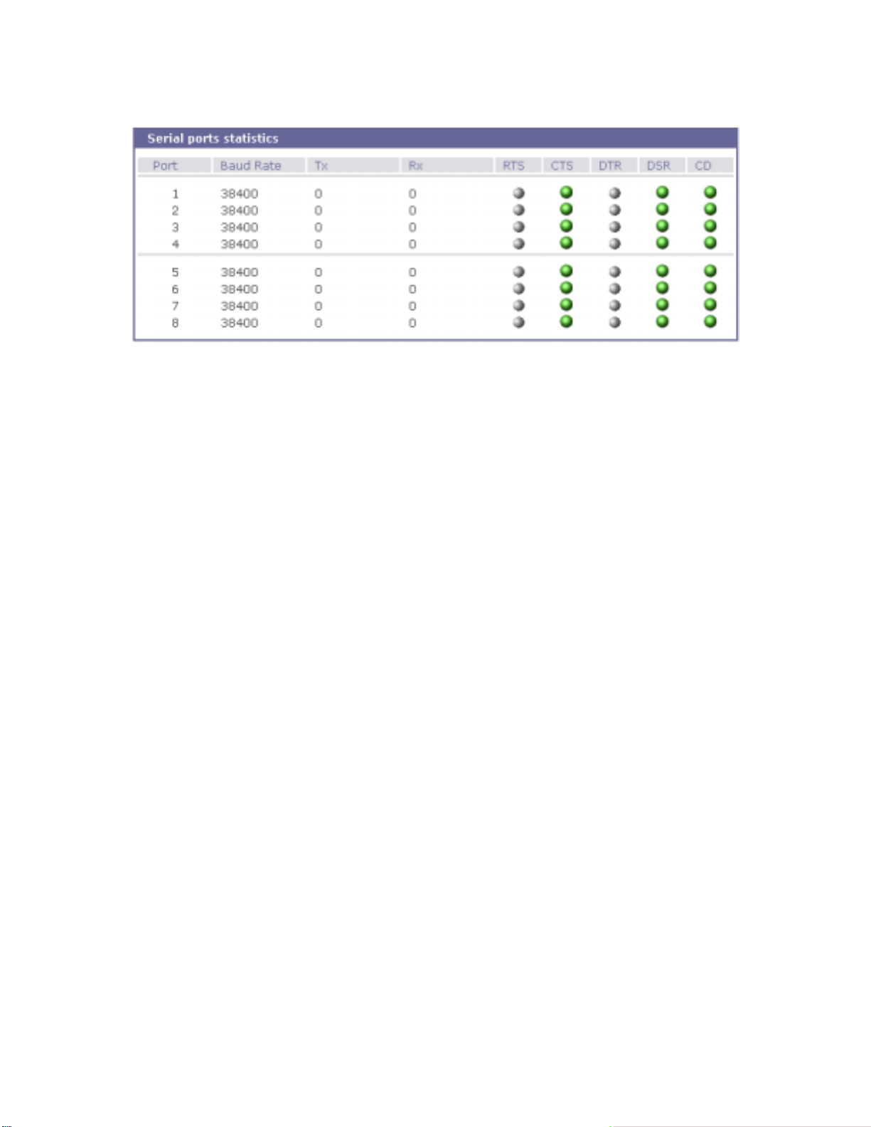
Figure 7-2 S erial ports status
7.3. IP Statistics
The IP Statistics screen provides statistical information about packets/connections using an IP
protocol. Definitions and descriptions of each parameter are described below:
Forwarding :
Specifies whether IP forwarding is enabled or disabled.
DefaultTTL :
Specifies the default initial time to live (TTL) for datagrams originating on a particular computer.
InReceives :
Shows the number of datagrams received.
InHdrErrors :
Shows the number of datagrams received that have header errors. Datagrams Received Header
Errors is the number of input datagrams discarded due to errors in their IP headers, including bad
checksums, version number mismatch, other format errors, time-to-live exceeded, errors
discovered in processing their IP options, etc.
InAddrErrors :
Specifies the number of datagrams received that have address errors. These datagrams are
discarded because the IP address in their IP header's destination field was not a valid address to
be received at this entity. This count includes invalid addresses (for example, 0.0.0.0) and
addresses of unsupported Classes (for example, Class E).
ForwDatagrams :
Specifies the number of dat agrams forwarded.
InUnknownProtos :
Specifies the number of locally addressed datagrams received successfully but discarded because
of an unknown or unsupported protocol.
86
Page 87

InDiscard :
Specifies the number of input IP datagrams for which no problems were encountered to prevent
their continued processing, but which were discarded (for example, for lack of buffer space). This
counter does not include any datagrams discarded while awaiting reassembly.
InDelivers :
Specifies the number of received datagrams delivered.
OutRequests :
Specifies the number of outgoing datagrams that an IP is requested to transmit. This number does
not include forwarded datagrams.
OutDiscards :
Specifies the number of outgoing datagrams discarded.
OutNoRoutes :
Specifies the number of datagrams for which no route could be found to transmit them to the
destination IP address. These datagrams were discarded. This counter includes any packets
counted in Datagrams Forwarded that meet this "no route" criterion.
ReasmTimeout :
Specifies t he amo unt o f time al lo wed fo r all pi eces of a fragmented datagram to arrive. If all pieces
do not arrive within this time, the datagram is discarded.
ReasmReqds :
Specifies the number of datagrams that require reassembly.
ReasmOKs :
Specifies the number of datagrams that were successfully reassembled.
ReasmFails :
Specifies the number of datagrams that cannot be reassembled.
FragOKs :
Specifies the number of dat agrams that were fragmented successfully.
FragFails :
Specifies the number of datagrams that need to be fragmented but couldn't be because the IP
header specifies no fragmentation. For example, if the datagrams "Don't Fragment" flag was set,
the datagram would not be fragmented. These datagrams are discarded.
FragCreates :
Specifies the number of fragments created.
87
Page 88
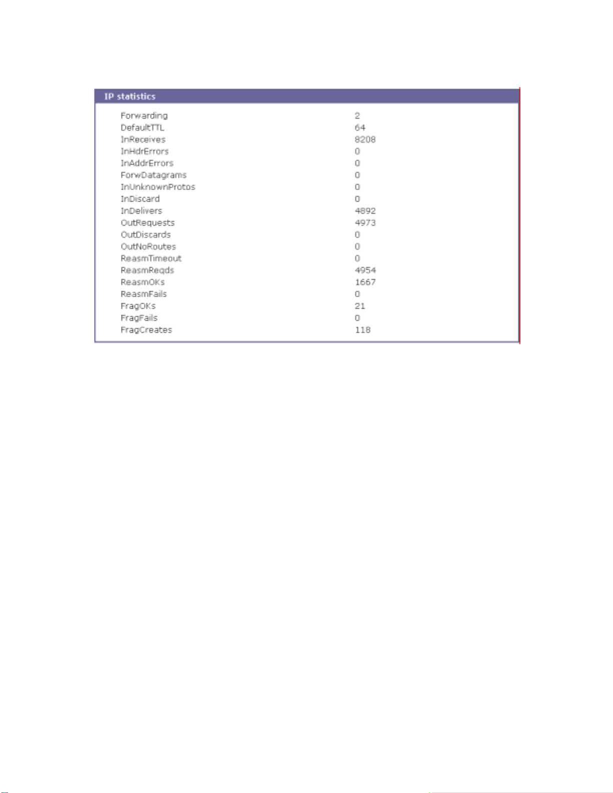
Figure 7-3 IP statistics
7.4. ICMP Statistics
The ICMP Statis tics screen pro vides stat istical info rmation about packets/c onnections using an ICMP
protocol. Definitions and descriptions of each parameter are described below:
InMsgs, OutMsgs :
Specifies the nu m b er of m essages received or sent.
InErrors, OutErrors :
Specifies the number of errors received or sent.
InDestUnreachs, OutDestUnreachs :
Specifies the number of destination-unreachable messages received or sent. A destinationunreachable message is sent to the originating computer when a datagram fails to reach its
intended destination.
InTimeExcds, OutTimeExcds :
Specifies the number of time-to-live (TTL) exceeded messages received or sent. A time-to-live
exceeded mes sage is sent to t he origi natin g compu ter whe n a data gram is discar ded beca use th e
number of routers it has passed through exceeds its time-to-live value.
InParmProbs, OutParmProbs :
Specifies the number of parameter-problem messages received or sent. A parameter-problem
message is sent to the originating computer when a router or host detects an error in a datagram's
IP header.
88
Page 89

InSrcQuenchs, OutSrcQuenchs :
Specifies the number of source quench messages received or sent. A source quench request is
sent to a computer to request that it reduces its rate of packet transmission.
InRedirects, OutRedirects :
Specifies the number of redirect messages received or sent. A redirect message is sent to the
originating computer when a better route is discovered for a datagram sent by that computer.
InEchos, OutEchos :
Specifies the number of echo requests received or sent. An echo request causes the receiving
computer to send an echo reply message back to the originating computer.
NEchoReps, OutEchoReps :
Specifies the number of echo replies received or sent. A computer sends an echo reply in
response to receiving an echo request message.
InTimestamps, OutTimestamps :
Specifies the number of time-stamp requests received or sent. A time-stamp request causes the
receiving computer to send a time-stamp reply back to the originating c omputer.
InTimestampReps, OutTimestampReps :
Specifies the number of time-stamp replies received or sent. A computer sends a time-stamp reply
in response to receiving a time-stamp request. Routers can use time-stamp requests and replies to
measure the transmission speed of datagrams on a network.
InAddrMasks, OutAddrMasks :
Specifies the number of address mask requests received or sent. A computer sends an address
mask request to determine the number of bits in the subnet mask for its local subnet.
InAddrMaskReps, OutAddrMaskReps :
Specifies the number of address mask responses received or sent. A computer sends an address
mask response in response to an address mask request.
89
Page 90
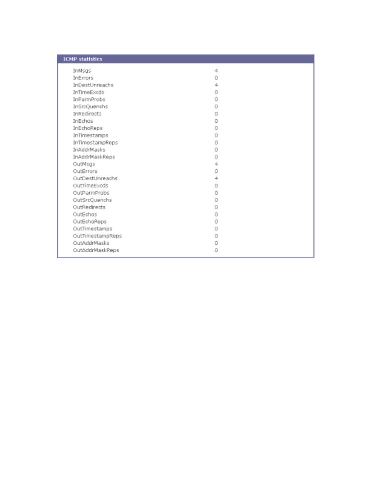
Figure 7-4 ICMP statistics
7.5. TCP Statistics
The TCP Statistics screen provides statistical information about packets/connections using a TCP
protocol. Definitions and descriptions of each parameter are described below:
RtoAlgorithm :
Specifies the retransmission time-out (RTO) algorithm in use. The Retransmission Algorithm can
have one of the following values.
0 : CONSTANT - Constant Time-out
1: RSRE - MIL-STD-1778 Appendix B
2: VANJ - Van Jacobso n' s Algorithm
3: OTHER - Other
RtoMin :
Specifies the minimum retransmission time-out value in milliseconds.
RtoMax :
Specifies t he maximum retransmission time-out v alue in milliseconds.
90
Page 91

MaxConn :
Specifies the maximum number of connections. If is the maximum number is set to -1, the
maximum number of connections are dynamic.
ActiveOpens :
Specifies the number of active opens. In an active open, the client is initiating a connection with the
server.
PassiveOpens :
Specifies the number of passive opens. In a passive open, the server is listening for a connection
request from a client.
AttemptFails :
Specifies the number of failed connection attempts.
EstabResets :
Specifies the number of established connections that have been reset.
CurrEstab :
Specifies the number of currently established connections.
InSegs :
Specifies the number of segments received.
OutSegs :
Specifies the number of segments transmitted. This number does not include retransmitted
segments.
RetransSegs :
Specifies the number of segments retransmitted.
RetransSegs :
Specifies the number of errors received.
OutRsts :
Specifies the number of segments transmitted with the reset flag set.
91
Page 92
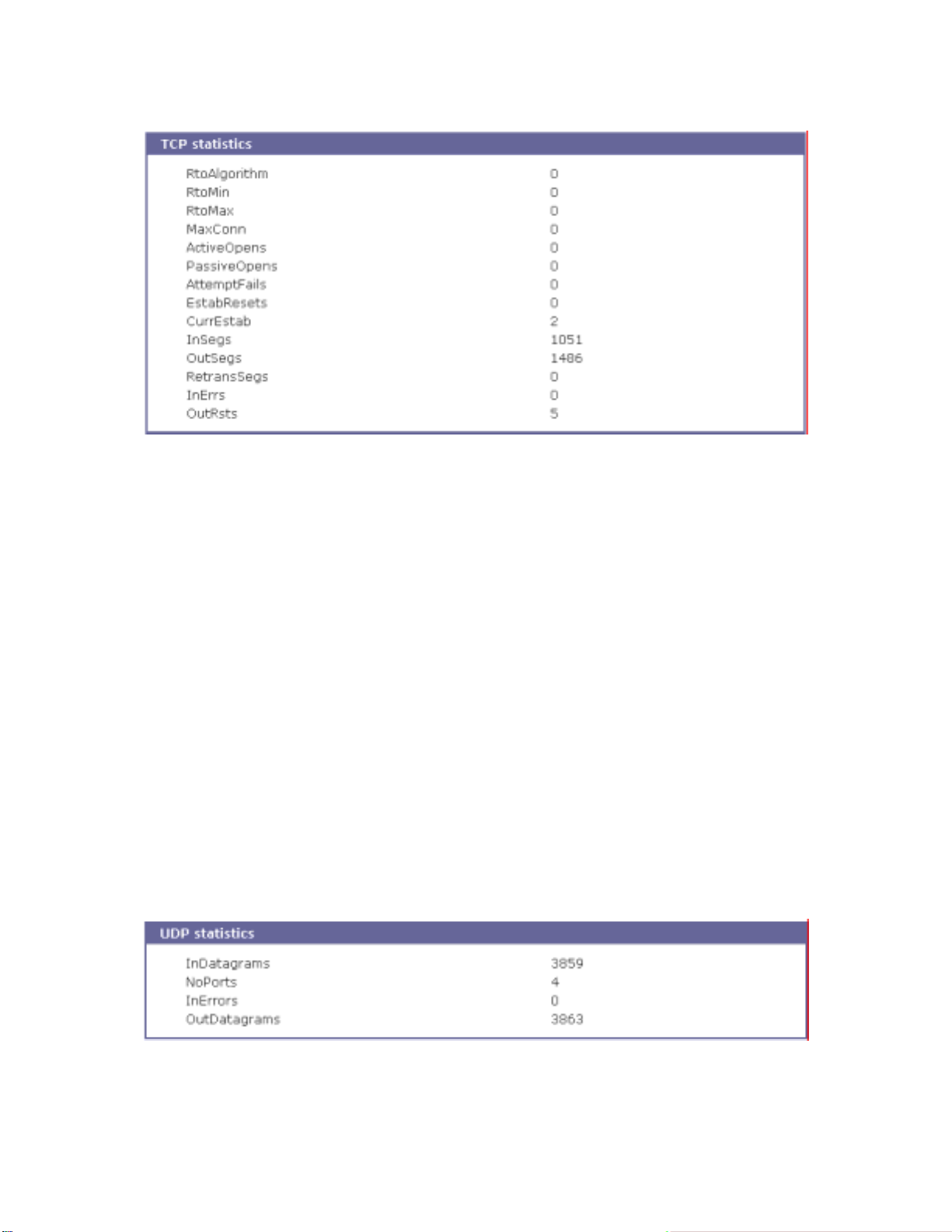
Figure 7-5 TCP statistics
7.6. UDP Statistics
The UDP Statistics screen provides statistical information about packets/connections using a
UDP protocol. Definitions and descriptions of each parameter are described below:
InDatagrams :
Specifies the number of dat agrams received.
NoPorts :
Specifies the number of received datagrams that were discarded because the specified port was
invalid.
InErrors :
Specifies the number of erroneous datagrams that were received. Datagrams Received Errors is
the number of received UDP datagrams that could not be delivered for reasons other than the lack
of an application at the destination port.
OutDatagrams :
Specifies the number of dat agrams transmitted.
Figure 7-6 UDP statistics
92
Page 93

8. CLI guide
8.1. Introduction
The STS Series root or System Administrator (only admin account is added for this group user by
factory default) can access the Linux console command line interface (CLI) of the STS Series via the
serial console or TELENT/SSH. In the CLI, the authorized user can perform standard Linux commands
to view the status of the STS Series, edit the configuration, apply configuration changes, define user
scripts and transmit files between the STS Series and remote hosts.
The STS Series provides 1024 KB user space mounted in /usr2 for read/write capabilities in its
internal flash memory. Using the user space, the user can create his own scripts or executable
binaries to customize the STS Series.
A root user will always have access to the CLI through the serial console on the STS Series back
panel or by using a Telnet client from thei r workstation.
A
System Administrator
configuration menu or Web UI.
cannot have access to the CLI. He can only access console
8.2. Flash partition
The STS Series internal flash is part itioned as shown in the table below. The users can freely access
the Mtdblock5 which is mounted on /usr2 for their own needs. The user can also access files at /etc,
/var, and /temp at their own risk. Simply accessing these files will not affect the STS Series after
rebooting. However, if the user invokes the command saveconf, the changes in the configuration file
will be committed to the internal flash memory area of the STS Series. This will result in the changes
being kept after the reboot sequence. Invalid configuration changes can affect the STS Series
behavior. At worst, it may cause the STS Series to be inoperable.
Block Type Mou nt poi nt Size (KB)
Mtdblock0 Bootloader None 128
Mtdblock1 Kernel None 768
Mtdblock2 CRAMFS (Read only) / 6080
Mtdblock3 Ram disk image (4MB) /etc, /var, /tmp 64
Mtdblock4 EXT2 (R/W) /cnf (normally unmounted) 64
Mtdblock5 JFFS2 (R/W) /usr2 1024
Mtdblock6 Reserved None 64
Total 8192
93
Page 94

8.3. Supported Linux Utilities
8.3.1. Shell & shell utilities:
sh, ash, bas h, echo, env, false, grep, more, sed, which, pwd
8.3.2. File and disk utils:
ls, cp, mv, rm, mkdir, rmdir, ln, mknod, chmod, touch, sync,
gunzip, gzip, zcat, tar, dd, df, du, find, cat, vi, tail,
mkdosfs, mke2fs, e2fsck, fsck, mount, umount, scp
8.3.3. System utilities:
date, free, hostname, sleep, stty, uname, reset,
insmod, rmmod, lsmod, modprobe,
kill, killall, ps, halt, shutdown, poweroff, reboot, telinit, init,
useradd, userdel, usermod, whoami, who, passwd, id, su, who
8.3.4. Network utilities:
ifconfig, iptables, route, telnet, ftp, ssh, ping
8.4. Accessing CLI as root or system administrator
Serial cons ole:
1) Connect the console port of the STS Series with the PC serial port
2) Run the PC terminal emulation program
3) Configure the PC serial port to: 9600-8-N-1 No flow control
4) Press <enter>
5) Login with the STS Series root or admin account
Telnet console:
1) telnet STS Series_ip_address
8.5. Examples
8.5.1. Disabling the Telnet Port of the Unit
The STS Series unit does not support di sabling the remot e console port indi vidually (port 22 f or
SSH or port 23 for Telnet to the box)
Currently, the user can only disable or enable all remote consoles together. This must be done
94
Page 95

using the UI or console configuration menu.
The user may bypass this and disable only one (Telnet or SSH) remote console by modifying the
script 'rc.user'. Below are two examples of how this could be done.
Example1. Modify 'inetd.conf'
Step 1 Modify /etc/inetd.conf (comment out or delete telnet service)
Copy inetd.conf to /usr2/inetd.conf
Step 2
Step 3
Edit
usr2/rc.user
script as follows:
#!/bin/bash
#
# rc.user : Sample script file for running user programs at boot time
#
#PATH=/bin:/usr/bin:/sbin:/usr/sbin
# Add shell command to execute from here
# Add shell command to execute from here
cp -a /usr2/inetd.conf /etc/inetd.conf
ps -ef
while killall inetd 2>/dev/null;
do sleep 1;
ps -ef
done
/usr/sbin/inetd
ps -ef
exit 0
The user may now disable the telnet service every time the system boots up.
Example 2. Run iptables rule
Step 1 Modify 'usr2/rc.user script as follows:
#!/bin/bash
#
# rc.user : Sample script file for running user programs at boot time
#
#!/bin/bash
#
# rc.user : Sample script file for running user programs at boot time
#
#PATH=/bin:/usr/bin:/sbin:/usr/sbin
# Add shell command to execute from here
# if user wants to disable telnet service from all host
iptables -A INPUT -p tcp -s --dport 23 -j DROP
# if user wants to enable telnet service only from specific hosts(192.168.0.0 ~
95
Page 96

192.168.0.255)
#iptables -A INPUT -p tcp -s ! 192.168.0.1/255.255.255.0 --dport 23 -j DROP
exit 0
The user may now disable the telnet service every time the system boots up.
If the user resets the STS Series to the factory defaults, /usr2/rc.user script file will be renamed to
/usr2/rc.user.old# file, and the default rc.user file will be restored.
8.5.2. Periodical program execution
User can use crontab to execute a specific program periodically. To enable periodical jobs using
crontab, please complete following steps,
Step 1 Create a crontab file on /usr2 directory. Following sample crontab file generates
current_date file under /tmp directory and revise its contents every 2 minutes.
SHELL=/bin/bash
# Sample crontab job
# Run every two minutes
* * * * * echo `date` > /tmp/current_date
Register crontab file using following command.
Step 2
root@STS800_Device:/usr2# crontab samplecrontab_file
Step 3 To make cron job permanent for every system reboot, please use rc.user script as follows:
#!/bin/bash
#
# rc.user : Sample script file for running user programs at boot time
#
#PATH=/bin:/usr/bin:/sbin:/usr/sbin
# Add shell command to execute from here
crontab /usr/samplecrontab_file
exit 0
Please note that –e option (editing current crontab using editor) is not supported in STS. So user must
user vi editor to change contents in crontab file.
For more information about the format of crontab file, please refer to Linux crontab manual(man 5
crontab).
96
Page 97

Appendix 1. Connections
A 1.1. Ethernet Pin outs
The STS Series uses the standard Ethernet connector that is shielded connector compliant with
AT&T258 specifications. Table A-1 shows the pin assignment and wire color.
Figure A-1 Pin layout of the RJ45 connector
Table A-1 Pin assignment of the RJ45 connector for Ethernet
Pin Description Color
1 Tx+ White with orange
2 Tx- Orange
3 Rx+ White with green
4 NC Blue
5 NC White with blue
6 Rx- Green
7 NC White with brown
8 NC Brown
A 1.2. Console and Serial port pin-outs
The STS Series uses an RJ45 connector for console and serial ports. The pin assignment of the RJ45
connector for console and serial ports is summarized in Tab le A- 2. Eac h pin has a func tion acco rding
to the serial communication type configuration.
Table A-2 Pin assignment of RJ45 connector for console and serial ports
Pin RS232
1 CTS
2 DSR
3 RxD
4 GND
5 DCD
6 TxD
7 DTR
8 RTS
(console and
serial ports)
97
Page 98
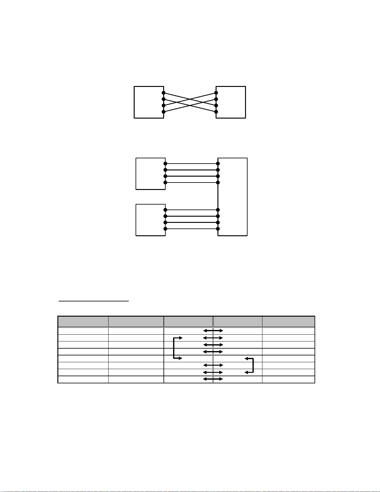
A 1.3. Ethernet Wiring Diagram
HelloDevice
Rx+(1)
Rx-(2)
Tx+(3)
Tx-(6)
Remote Host
Rx+(1)
Rx-(2)
Tx+(3)
Tx-(6)
Figure A-2 Ethernet direct connection using crossover Ethernet cable
HelloDevice
Rx+(1)
Rx-(2)
Tx+(3)
Tx-(6)
Hub
Rx+(1)
Rx-(2)
Tx+(3)
Tx-(6)
Remote Host
Rx+(1)
Rx-(2)
Tx+(3)
Tx-(6)
Rx+(1)
Rx-(2)
Tx+(3)
Tx-(6)
Figure A-3 Ethernet connection using straight through Ethernet cable
A 1.4. RS232 Serial Wiring Diagram
RJ45-DB9 female adapter
Using RJ45 to DB9(Female)
Description (RJ45) I nternal Cable Color RJ45 Pin No. DB9 Pin No. Descrip tion (DB9)
CTS Blue 1 7 RTS
DSR Orange 2 4 DTR
RXD Black 3 3 TXD
GND Red 4 5 GND
DCD Green 5 1 DCD
TXD Yellow 6 2 RXD
DTR Brown 7 6 DSR
RTS White 8 8 CTS
Cross-over
Cable
98
Page 99
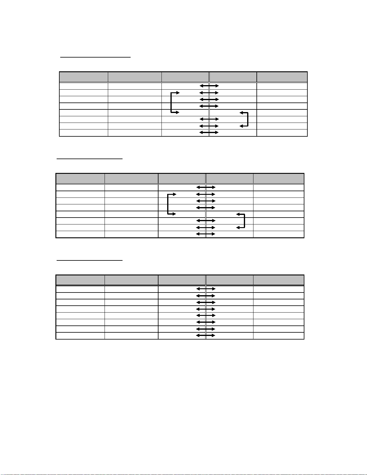
RJ45-DB25 female adapter
Using RJ45 to DB25(Female)
Description (RJ45) I nternal Cable Color RJ45 Pin No. DB25 Pin No. Description (DB25)
CTS Blue 1 4 RTS
DSR Orange 2 20 DTR
RXD Black 3 2 TXD
GND Red 4 7 GND
DCD Green 5 8 DCD
TXD Yellow 6 3 RXD
DTR Brown 7 6 DSR
RTS White 8 5 CTS
Cross-over
Cable
RJ45-DB25 male adapter
Using RJ45 to DB25(Male)
Description (RJ45) I nternal Cable Color RJ45 Pin No. DB25 Pin No. Description (DB25)
CTS Blue 1 4 RTS
DSR Orange 2 20 DTR
RXD Black 3 2 TXD
GND Red 4 7 GND
DCD Green 5 8 DCD
TXD Yellow 6 3 RXD
DTR Brown 7 6 DSR
RTS White 8 5 CTS
Cross-over
Cable
RJ45-DB25 male adapter
Using RJ45 to DB25(Male)
Description (RJ45) I nternal Cable Color RJ45 Pin No. DB25 Pin No. Description (DB25)
CTS Blue 1 5 CTS
DSR Orange 2 6 DSR
RXD Black 3 3 RXD
GND Red 4 7 GND
DCD Green 5 8 DCD
TXD Yellow 6 2 TXD
DTR Brown 7 20 DTR
RTS White 8 4 RTS
Straight
Cable
99
Page 100

Appendix 2. PC card supported by STS
The following PC cards are supported by the STS Series series:
Table A-3 Network card
Manufacturer Model/Name STS probed Model name Specification
3COM 3CXE589ET-AP 3Com Megahertz 589E
Linksys Linksys EtherFast 10/100
Integrated PC Card
(PCM100)
Corega FetherII PCC-TXD corega K.K. corega FEtherII
Netgear 16bit PCMCIA Notebook Adapter
FA411
TP/BNC LAN PC Card
Linksys EtherFast 10/100
Integrated PC Card
(PCM100) Ver 1.0
PCC-TXD
NETGEAR FA411 Fast
Ethernet
Table A-4 Wireless Network card
Manufacturer Model/Name STS probed Model name Specification
Cisco Systems AIR-PCM340/Aironet 340 Cisco Systems 340 Series
Lucent
Technologies
Lucent
Technologies
Agere Systems
(Lucent
Technologies)
Buffalo AirStation
PC24E-H-FC/Orinoco Silver Lucent Technologies
PC24E-H-FC/Orinoco Gold Lucent Technologies
Orinoco Classic Gold
(PC24E-H-FC/Orinoco Gold)
(WLI-PCM-L11GP)
Wireless LAN Adapter
WaveLAN/I EEE Version
01.01
WaveLAN/I EEE Version
01.01
Lucent T echnologies
WaveLAN/I EEE Version
01.01
MELCO WLI-PCM-L11
Versio n 01.01
10 Mbps LAN card
10/100 Mbps LAN card
10/100 Mbps LAN card
10/100 Mbps LAN card
11 Mbps Wireless LAN
Adapter
11 Mbps Wireless LAN
Adapter
11 Mbps Wireless LAN
Adapter
11 Mbps Wireless LAN
Adapter
11 Mbps Wireless LAN
Adapter
Table A-5 ATA/IDE Fixed Disk Card
Manufacturer Model/Name STS probed Model name Specification
Advantech CompactFlash CF 48M 48 MB Storage card
SanDisk SDP series SunDisk SDP 5/3 0.6 64 MB Storage card
SanDisk SDP series SanDisk SDP 5/3 0.6 256 MB Storage card
Kingston CompactFlash Storage Card TOSHIBA THNCF064MAA 64 MB Storage card
Viking CompactFlash TOSHIBA THNCF064MBA 64 MB Storage card
100
 Loading...