


SEMITEC Z1100, Z1120, Z10D470, Z10D471, Z10D511 Datasheet
...PRODUCT CATALOG
CAT. No.129E

SURGE ABSORBERS
SENSORS AND MODULES
THERMISTORS

NON-CONTACT SENSOR |
4 |
 THERMOPILE
 NC SENSOR
THERMISTOR |
6 |
|
|
HIGH PRECISION SERIES |
|
|
|
SMD SERIES |
|
|
|
HIGH HEAT-RESISTANCE SERIES |
|
|
|
DISK SERIES |
|
|
|
SENSORS |
|
|
|
|
|
|
|
POWER THERMISTOR |
21 |
|
|
D-TYPE SERIES |
|
|
|
 MARK
MARK 
 SERIES
 D2-TYPE SERIES
VRD (TRANSIENT VOLTAGE SUPPRESSOR) |
26 |
 LEAD TYPE SERIES
 SMD SERIES
CRD (CURRENT REGULATIVE DIODE) |
30 |
 LEAD TYPE SERIES
 MELF TYPE SERIES
ZENAMIC (METAL OXIDE VARISTOR) |
32 |
 LEAD TYPE SERIES
 M TYPE SERIES
 SURGE ABSORBER UNIT SERIES
GAS TUBE ARRESTER |
40 |
 CERAMIC TUBE SERIES
 GLASS TUBE SERIES
 SA-01 SERIES
3
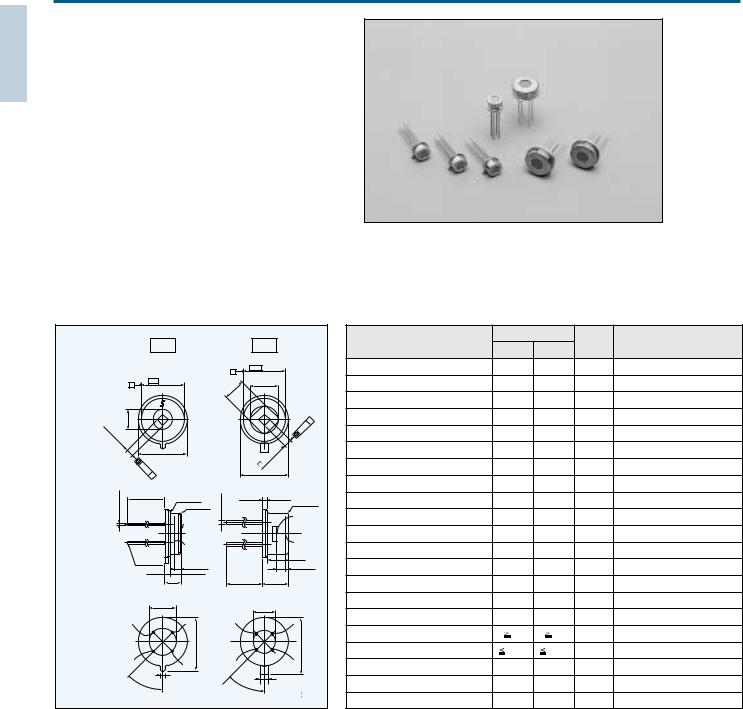
THERMOPILE TYPE INFRARED SENSOR
THERMOPILE
Thermopile type Infrared sensor utilizing own silicon micromachining technology.
Applications:Eardrum thermometer Microwave oven
Non contact temparature measurement
Part number
Part No. |
type |
Thermistor |
|
15TP551T |
TO5 |
Built-in |
|
15TP551N |
|
||
|
|||
10TP581T |
TO18 |
Built-in |
Dimensions |
|
|
|
|
|
|
|
|
|
|
|
|
Ratings |
|
|
|
|
|
|
|
|
|
|
|
|
|
|
|
|
|
|
|
|
|
|
|
Parameters |
Value |
Unit |
Conditions |
|||
|
|
TO5 |
|
|
|
|
TO18 |
|
|
|
|
|
|
||||||||
|
|
|
|
|
|
|
|
|
|
|
|
|
15TP551 |
10TP581 |
|
|
|||||
|
|
|
|
|
|
|
|
|
|
|
|
|
|
|
|
|
|
|
|
||
|
|
|
|
|
|
|
|
|
4.65 0.05 |
|
|
|
|
Sensitive area |
1.56 1.56 |
1.05 1.05 |
mm2 |
Size of Absorbing Film |
|||
|
|
|
|
|
|
|
|
A |
|
|
|
|
|
|
|
|
|
|
|
|
|
|
|
8.2 |
0.05 |
|
|
|
|
0.1.4 |
(3.12) |
|
|
|
|
* |
1 |
Responsivily |
16 30% |
15 30% |
V/ W |
|
|
|
|
A |
|
|
|
|
|
|
0 |
|
|
|
|
|
|
|
|||||
|
|
|
|
|
|
|
|
.4 |
|
|
|
|
|
|
|
|
|
|
|
|
|
|
|
|
|
|
|
|
|
2 |
|
|
|
|
|
|
|
|
|
|
|
|
|
|
3.80.05 |
|
|
|
|
|
|
|
|
|
|
|
|
|
*1 Output Voltage |
490 30% |
200 30% |
V |
|
||
. |
5 |
|
|
1 |
|
|
|
|
|
|
|
* |
|
Temperature Coefficient |
2.49 30% |
1.00 30% |
mV |
|
|||
(TOP VIEW) |
|
|
|
|
|
|
|
|
|
|
|
A |
|
|
*2 |
Output Voltage |
|
||||
1 |
|
1 |
|
|
|
1 |
|
|
|
|
.7 |
|
1 |
|
|
|
|
|
|
|
|
|
5 |
|
|
|
|
|
|
|
|
|
|
|
|
|
|
|
|
||||
|
|
|
|
|
|
|
|
|
0 |
|
|
|
|
|
|
|
|
|
|||
56 |
|
1 |
T |
0 |
|
|
|
|
|
|
|
|
|
|
|
|
|
0.01 0.02 |
0.02 0.02 |
% / C |
Reference |
|
0 |
|
|
|
|
|
|
|
|
|
|
of Responsivily |
|||||||||
|
0 |
|
|
|
|
|
|
|
|
|
|
|
|
|
|
|
|
|
|||
|
. |
|
|
|
|
|
|
|
|
|
|
|
|
|
|
|
|
|
|
|
|
|
01 |
|
|
|
|
|
|
|
|
.01 |
|
|
|
|
|
|
|
|
|
|
|
|
|
9.4 max |
|
|
|
|
|
|
|
|
|
Thermopile Resistans |
55 30% |
65 30% |
k |
|
|||||
|
|
|
|
|
|
|
0 |
|
|
|
|
|
|||||||||
|
|
|
|
|
|
|
|
|
|
|
|
|
|
|
|
|
|
|
|
|
|
|
|
|
|
|
|
|
|
|
|
.05 |
|
|
|
Temperature Coefficient |
|
|
|
|
|||
|
|
|
|
|
|
|
|
|
1 |
|
|
|
0.1 |
0.1 |
% / C |
|
|||||
|
|
. |
|
|
|
|
|
|
|
|
|
|
|
|
|
|
|
|
|||
|
|
0 |
|
|
|
|
|
|
|
|
|
|
of Thermopile Resistance |
|
|
|
|
||||
|
|
8 |
|
|
|
|
|
|
5.6 max |
|
|
|
|
|
|
||||||
|
|
A |
|
|
|
|
|
|
|
|
|
|
|
|
|
|
|
|
|
||
|
|
|
|
|
|
|
|
|
|
|
|
|
|
|
Johnson Noise Voltage |
30 |
33 |
nV/ |
Johnson Noise r.m.s.,298K 1Hz Typical |
||
0.450.03 |
|
|
|
|
|
|
|
|
|
|
|
|
|
|
|
|
|
|
|
Hz |
|
|
13.2 0.5 |
|
|
R 0.3 max |
0.050.03 |
|
|
0.55 0.2 |
|
|
|
|
*1 S/N Ratio |
84.2 |
75.7 |
dB |
Output Voltage/Johnson Noise, Typical |
||||
|
|
|
|
|
|
|
|
R 0.3 max |
|
|
|
||||||||||
|
|
|
|
|
R 0.5 max |
0.45 |
|
|
|
*1 Noise Equivalent Power |
1.9 |
2.2 |
nW/ Hz1/2 |
Typical |
|||||||
|
|
|
|
|
|
|
|
SENSOR |
|||||||||||||
|
|
|
|
|
|
|
|
|
|
|
|
|
|
|
|
|
|
|
|
|
|
|
|
|
|
|
|
FILTER |
|
|
|
|
SURFACE |
|
|
|
|
|
|
|
|
|
|
|
|
|
|
|
|
SURFACE |
|
|
|
|
|
|
|
|
|
|
|
|
|
|
|
(SIDE VIEW) |
|
|
|
|
|
SENSOR |
|
|
|
|
|
|
|
|
*1 Specific Detecivity |
8.4 107 |
4.7 107 |
cm•Hz1/2/ w |
Typical |
||
|
|
|
|
|
|
|
|
|
|
FILTER |
|
|
|
|
|
|
|
|
|
||
|
|
|
|
|
|
SURFACE |
|
|
|
|
SURFACE |
|
|
Time Constant |
45 |
15 |
ms |
Typical |
|||
|
|
|
|
|
|
OPTICAL |
|
|
|
|
(2.4) |
|
|
|
|||||||
|
|
Au plated |
|
|
DISTANCE |
|
|
|
|
|
|
|
|
|
|
|
|
|
|
||
|
|
|
|
|
|
|
|
1.25 0.2 |
|
|
|
|
|
|
|
|
|
||||
|
|
|
|
1.35 0.2 |
|
|
|
|
Operating Temperature range |
20 100 |
20 100 |
C |
|
||||||||
|
|
1 0.2 |
|
|
|
|
|
|
|
||||||||||||
|
|
|
|
2.2 0.1 |
|
|
|
|
OPTICAL |
|
|
|
|
|
|
|
|
|
|||
|
|
|
|
3.2 00..13 |
|
|
|
|
|
|
|
|
|
|
|
|
|
||||
|
|
|
|
|
|
13.2 0.5 |
2.95 0.2 |
DISTANCE |
Strage Temperature renge |
40 100 |
40 100 |
C |
|
||||||||
|
|
|
|
|
|
|
|
|
|
|
|
|
|
||||||||
|
|
5.08 0.2 |
|
|
|
|
2.54 0.2 |
|
|
|
|
|
Filter Range |
Cut on 5 |
Cut on 5 |
m |
Standard |
||||
|
|
|
|
|
|
|
|
|
|
|
|
|
|
|
|
|
|||||
|
|
|
|
|
|
|
|
|
|
|
|
|
|
|
|
|
|
|
|
||
|
|
2 |
|
|
|
3 |
|
2 |
|
3 |
|
|
|
|
Field of View |
45 |
50 |
deg. |
Incident Angle to Ahieve 50% Responsivity |
||
|
|
|
|
|
|
|
|
|
|
|
|
|
|
|
|
|
|||||
|
|
|
|
|
|
|
|
|
|
|
|
|
|
|
|
|
|
|
|
|
|
|
|
|
|
|
|
10.3max |
|
|
|
|
6.6max |
|
|
|
Insulation Rasistance |
500 |
500 |
M |
Application of DC25V |
||
(BOTTOM VIEW) |
|
|
|
|
|
|
|
|
|
|
|
|
|
|
Sealing |
1 10 9 |
1 10 9 |
Pa•m3/ s |
|
||
|
|
1 |
|
|
|
4 |
|
|
1 |
|
4 |
|
|
|
|
|
|
|
|
|
|
|
|
|
|
|
|
|
|
|
|
*3 Thermistor Resistance Value |
100 3% |
100 3% |
k |
Rated zero-power resistance Value at 25 C |
|||||||
|
|
|
|
|
|
|
|
|
|
|
|
||||||||||
|
|
0.8 0.1 |
|
|
|
|
|
|
|
1.8 max |
|
|
|
|
|
|
|
|
|
|
|
|
|
45 3 |
|
|
|
|
|
|
4.5 3 |
|
|
|
*3 Thermistor B-Value |
3435 0.7% |
3435 0.7% |
K |
|
||||
|
|
|
|
|
|
|
|
|
|
|
|
|
|
||||||||
|
|
|
|
|
|
|
|
|
|
|
Unit mm |
*3 Thermistor Rated Power |
0.5 |
0.5 |
mW |
at 25 C |
|||||
|
|
|
|
|
|
|
|
|
|
|
|
|
|||||||||
*1 Test Condition |
|
*2 |
Test Condition |
|
Blackbody Temperature |
: 500K |
|
Blackbody Temperature |
: 310K |
Sensor-Blackbody Distance |
: 100mm |
|
Sensor Temperature |
: 298K |
Sensor Temperature |
: 298K |
|
|
|
Aperture size |
: 12.7mm |
*3 |
Built-in Type |
|
4

NON-CONTACT SENSOR (Infrared sensing temperature detector)
NC SENSOR
NC SENSOR is the remote temperature sensor consisting of two precision thermistors.
1.Features
•Larger output in comparison with other IR sensors.
•Operating temperature of up 150 C.
•Minimum negative influence caused by a dew and/or dust.
2.Applications
•Temperature measurment of the LBP and PPC heatroller.
•White goods such as microwave-ovens, air-conditioner, refrigerator and so on.
•Any other measurement requiring the remote-sensing.
3. Dimensions |
4.Specification |
|
|
|
|
|
|
|
|
Parameters |
F-type (for heat-roller) |
M-type (for microwave ovens) |
|
|
|
|
|
|
|
|
|
Conditions |
Performance |
Conditions |
|
F-type |
|
|
|
|
|
|
Performance |
||||
|
|
|
|
|
|
|
|
|
|
||
|
|
|
|
52.5 |
|
|
|
|
Blackbody Temperature : 180 C |
|
Blackbody Temperature : 60 C |
|
|
|
|
28 |
|
|
|
|
Thermal Emissivity : 0.96 |
|
Thermal Emissivity : 0.995 |
|
|
|
|
|
|
|
|
Temperature |
Temperature compensation : 100 C |
|
Temperature compensation : 25 C |
|
|
|
|
|
|
|
|
Roller Size : 40mm |
60 C 5 C |
Resistor Connected : 68.0 |
|
|
12.6 |
10 |
|
|
|
|
|
180 C 3 C |
|||
|
|
|
|
|
|
Accuracy |
Testing Distance : 5mm |
|
Power Line Voltage : DC 5.000V |
||
|
|
|
|
|
|
|
|
|
|||
|
|
|
|
|
|
|
|
|
|
||
|
3.2 |
|
|
3 |
|
|
|
|
Resistor Connected : 33.0 |
|
|
|
|
5 5.5 |
|
34.5 |
5 |
|
200 (120 300) |
|
Power Line Voltage : DC 5.000V |
|
|
|
|
|
|
Operating |
|
|
|
||||
|
|
|
|
|
|
|
|
|
|
|
|
|
5 |
|
|
|
|
1 |
|
Temperature |
10 C 150 C |
|
|
12 |
|
|
|
|
|
Range |
|
|
|
||
4 |
|
|
|
|
|
|
|
|
|
||
|
|
|
|
|
|
|
Unit mm |
Temperature |
|
|
|
|
|
|
|
|
|
|
Detecting |
10 C 260 C |
|
10 C 100 C |
|
|
|
|
|
|
|
|
|
|
|||
|
|
|
|
|
|
|
|
range |
|
|
|
M-type |
|
|
|
|
|
|
|
|
|
|
|
|
|
|
|
|
|
|
6 |
|
|
|
|
|
|
|
|
28 |
|
|
23 |
|
|
|
|
|
|
2 |
|
|
8 |
|
18 |
|
|
|
|
|
1 |
|
|
|
|
|
21.2 |
|
|
|
|
|
|
4.6 |
38 |
29.2 |
|
|
|
|
|
|
|
|
.6 |
|
|
|
|
|
|
|
|
|
|
|
5 |
|
|
|
|
|
|
|
|
|
|
|
|
8 |
|
|
|
|
160 (120 300) |
|
|
|
|
|
|
|
|
|
|
|
|
|
|
|
|
|
|
|
|
|
|
|
|
|
|
|
|
|
|
|
|
|
|
|
Unit mm |
|
|
|
|
5
THERMISTOR
"Thermistor" is the generic name given to thermally sensitive resistors.
Negative temperature coefficient thermistor is generally called as thermistor. Thermistor is a semiconducting ceramic resistor produced by sintering the materials at high temperature and made mainly from metal oxide.
Depending on the manufacturing method and the structure, there are many shapes and characteristics for various purposes such as temperature measurement, temperature compensation and etc.
The thermistor resistance values, unless otherwise specified, are classified at a standard temperature of 25 C.
B constant is calculated from the resistance values at 25 C and 85 C.
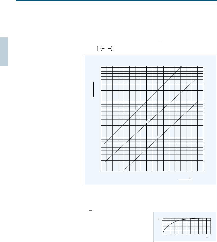
Resistance -Temperature Characteristics
The resistance of a temperature is solely a function of its absolute temperature. Since electrical power being dissipated within a temperature might heat above its ambient temperature and thereby reduce its resistance, it is necessary to test for resistance with temperature. The resistance so measured is called RT, which means the resistance at essentially zero-power.
The mathematical expression which relates the resistance and the absolute temperature of
a thermistor is as follows:
Where: Ra is the resistance at absolute temperature T1 Rb is the resistance at absolute temperature T2
Bis a constant which depends on the material of the thermistor
Unless otherwise specified,all values of B are determined from measurements made at 25 C and 85 C.
The temperature coefficient of resistanceis expressed in the following equation:
TB2 100(%/ C)
Ra Rb exp B |
1 |
1 |
|
|
|
|
|
|
|
|
|
|
|
|
|
|
|
|
|
|
T1 |
T2 |
|
|
|
|
|
|
|
|
|
|
|
|
|
|
|
|
|
||
|
|
|
|
|
|
|
|
|
|
|
|
|
|
|
|
|
|
|
||
|
100k |
|
|
|
|
|
|
|
|
|
|
|
|
|
|
|
|
|
|
|
) |
|
|
|
|
|
|
|
|
|
|
|
|
|
|
|
|
|
|
|
|
Resistance( |
10k |
|
|
|
|
|
|
|
|
|
|
|
|
|
|
|
|
|
|
|
|
|
|
|
|
|
|
B:3650 |
|
|
|
|
|
|
|
|
|
|
|
|
|
|
|
|
|
|
|
|
|
|
|
|
|
|
|
|
|
|
|
|
|
|
|
|
|
|
|
|
|
|
|
|
B:3350 |
|
|
|
|
|
|
|
|
|
|
|
1k |
|
|
|
|
|
|
|
|
|
|
B:3400 |
|
|
|
|
|
|
|
|
|
2.1 |
2.2 |
2.3 |
2.4 |
2.5 |
2.6 |
2.7 |
2.8 |
2.9 |
3.0 |
3.1 |
3.2 |
3.3 |
3.4 |
3.5 |
3.6 |
3.7 |
3.8 |
3.9 |
|
|
|
|
|
|
|
|
|
|
|
|
|
Temperature(1/ Tx103) |
|
|
|
|
|
|||
Dissipation factor
Dissipation factor ( ) is power in milliwatts required to raise thermistor temperature 1 C.
Measured with thermistor suspended by its leads in a specified environment.
P
t (mW/ C)
P:Power(mW)
t:Raise temperature( C)
Thermal time constant
Thermal time constant ( a) is the time required by a thermistor to change 63% of the difference between its initial and final temperature. Measured with thermistor suspended by its leads in specified environment.
|
95 |
|
|
|
(%) |
87 |
|
|
|
63 |
|
|
|
|
|
|
|
|
|
|
a |
2 a |
3 a |
5 a |
|
|
|
|
Time (s) |
6

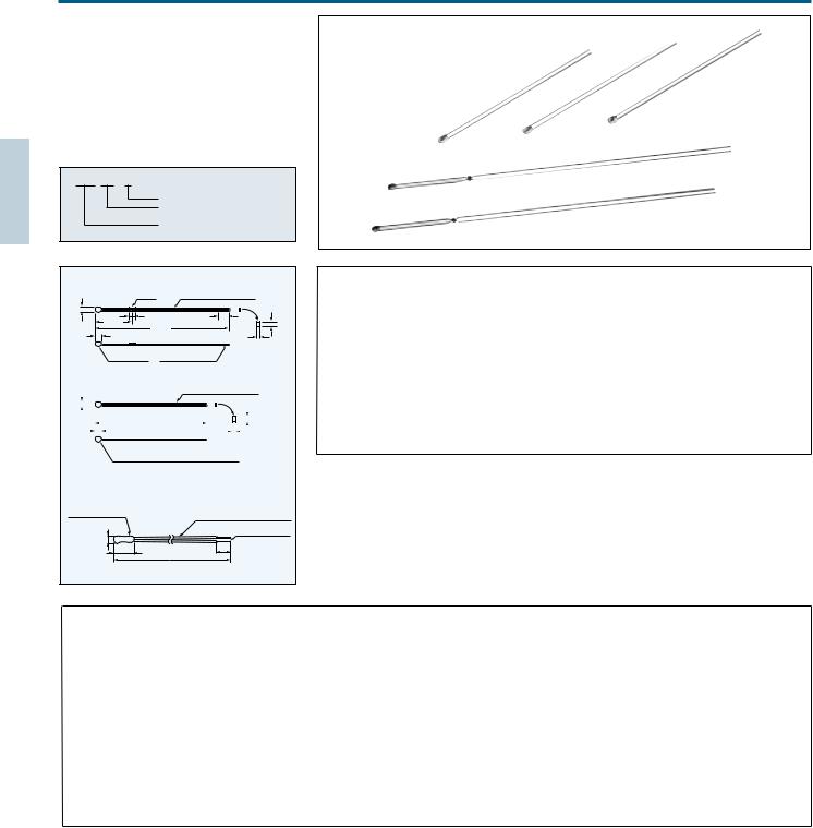
ULTIMATE THINNESS, JT THERMISTOR 500 m only
JT THERMISTOR
JT thermistors feature ultra thinness of 500 m and superior electrical insulation.
It is possible to use with safety in ambience that might contact with electrodes.
Part number
103 JT025
Shape
JT thermistor
Rated zero-power resistance at 25 C 103 : 10k
Dimensions
|
|
|
A |
|
||
3.6 0.5 |
|
|
5 1 |
|||
|
|
|
|
|
|
|
|
|
|
|
|
|
|
|
|
|
|
|
|
|
|
|
|
|
|
|
|
|
|
|
0.17 0.02 |
|
|
||
|
|
|
|
|
|
2.0 0.5 |
|
|
|
|
|
|
|
|
|
|
|||||
|
|
|
|
|
|
|
|
|
|
|
|
|
|
|
|
|
|
|
|||
|
|
|
|
|
|
|
|
|
|
|
|
|
|
|
|
|
|
|
|||
|
|
|
|
|
|
|
|
|
|
|
|
|
|
|
|
|
|
|
|
|
|
|
|
|
|
|
|
|
|
|
|
Tin plated |
wires |
|
|
|
|
|
|
|
|
||
|
|
|
|
|
|
|
|
|
|
|
|
1.8 0.1 |
|
|
|||||||
|
|
|
|
|
|
|
|
|
|
|
42 Alloy |
leads |
0.5 0.035 |
|
|
|
|
||||
0.5max. |
|
|
|
|
|
|
|
||||||||||||||
|
|
|
|
|
|
|
|
||||||||||||||
|
|
|
|
|
|
|
|
|
|
|
|
|
Slipped film : 1 max. |
|
|
|
|
|
|||
|
|
|
|
|
|
|
|
|
|
|
|
|
|
|
|
|
|
||||
|
|
|
|
|
|
|
|
|
|
|
|
|
Protruded adhesive : 1 max. |
|
|
|
|
|
|||
|
|
|
|
|
|
|
|
|
|
|
|
|
|
|
Shape |
Dimensions A |
|||||
|
|
|
|
|
|
|
|
|
|
|
|
|
|
|
|
|
|
|
|||
|
|
|
|
|
|
|
|
|
|
lnsulation film |
|
|
|
|
|
025 |
25 1 |
||||
|
|
|
|
|
|
|
|
|
|
|
|
|
|
|
|
|
|
||||
|
|
|
|
|
|
|
Adhesive |
|
lnsulation film |
|
|
|
|
050 |
50 1 |
||||||
|
|
|
|
|
|
|
|
|
|
|
|||||||||||
|
|
|
|
|
|
|
|
|
|
|
|
|
|
|
075 |
75 1 |
|||||
|
|
|
|
|
|
|
|
|
|
|
|
|
|
|
|
|
|
||||
|
|
|
|
|
|
|
|
|
|
|
|
|
|
Unit(mm) |
|
|
100 |
100 1 |
|||
|
|
|
|
|
|
|
|
|
|
|
|
|
|
|
|
|
|
|
|||
Specifications
Resistance-Temperature
Temperature |
|
Type |
|
( C) |
103JT |
|
104JT |
50 |
367.7 |
|
9584 |
40 |
204.7 |
|
4572 |
30 |
118.5 |
|
2282 |
20 |
71.02 |
|
1191 |
10 |
43.67 |
|
647.2 |
0 |
27.70 |
|
365.0 |
10 |
18.07 |
|
212.5 |
20 |
12.11 |
|
127.7 |
30 |
8.301 |
|
78.88 |
40 |
5.811 |
|
50.03 |
50 |
4.147 |
|
32.51 |
60 |
3.011 |
|
21.61 |
70 |
2.224 |
|
14.66 |
80 |
1.668 |
|
10.13 |
90 |
1.267 |
|
7.135 |
100 |
|
|
5.111 |
110 |
|
|
3.720 |
120 |
|
|
2.746 |
125 |
|
|
2.371 |
Unit(k )
Part No. |
R25*1 |
B value*2 |
Dissipation factor |
Thermal time |
Rated power |
Operating temp. |
|
(mW/ C) |
constant(s)*3 |
at 25 C(mW) |
range( C) |
||||
103JT- |
10k |
1% |
3435K 1% |
0.7 |
5 |
3.5 |
50 90 |
104JT- |
100k |
1% |
4390K 1% |
0.7 |
5 |
3.5 |
50 125 |
*1 R25 : Rated zero-power resistance value at 25 C, 2% and 3% are also available. *2 B value : determined by rated zero-power resistance at 25 C and 85 C.
*3 Time when thermistor temperature reaches 63.2% of the temperature difference. The value is measured in the air.
7

HIGH PRECISION THERMISTOR
AT THERMISTOR
The AT thermistor is a high-precision thermal sensing device featuring extremely small B-value tolerance and resistance.
When used as a temperature gauge, the AT thermistor requires no adjustment between the control circuit and the sensor.
This insures temperature precision of 0.3 C. Temperature indicators and control instruments are now available for use with the thermistor.
Part number
102 AT- 2
Shape
High-precision AT thermistor
Rated zero-power
Resistance at 25 C 102 : 1 k
k
Dimensions
AT-11
|
5 max. |
|
|
|
|
|
|
|
|
|
|
Marking |
0.3sq |
|
|
|
|
|
6 0.2 |
|
TPE lead wire |
Soldered |
||||
|
|
15 max. |
|
|
|
|
5 1 |
|
|
|
|
|
|
|
|
||
|
|
|
600 |
20 |
|
|
||
|
|
|
|
0 |
|
|
||
AT-2 |
|
|
3.8 max. |
|
|
|
2.4 max. |
|
1.5 |
8.51 |
|
max.4.0 |
|
|
|
Color code |
|
|
Tiebar cut |
|
|
|||||
|
|
|
|
|
|
|
Epoxy |
|
17 |
|
|
0.7 |
|
|
0.5 Tin-Plated |
||
|
|
|
|
|
|
|
||
|
|
|
|
|
|
|
42 Alloy |
|
|
|
|
2.54 0.25 |
|
|
|
|
|
AT-3 |
|
|
3.8 max. |
|
|
|
2.4 max. |
|
|
8.51 |
|
max.4.0 |
|
|
|
Color code |
|
1.5 |
|
|
|
|
Epoxy |
|||
17 |
|
|
|
Tiebar cut |
0.5 |
Tin-Plated |
||
|
|
1.0 |
|
|
|
|||
|
|
|
|
|
|
42 Alloy |
||
|
|
|
|
|
|
|
||
|
|
|
2.54 0.25 |
|
|
|
|
|
AT-4 |
|
|
|
|
|
|
|
|
Shape1 |
2.5max. |
Epoxy |
|
UL1685 AWG30 |
||||
|
|
|
||||||
|
|
|
8max. |
|
|
|
|
3 |
|
|
|
|
40 100 |
|
|
||
Shape2 |
|
Epoxy resin |
|
|
|
|||
|
|
|
|
|
|
|||
|
|
|
HVFF 0.14sq |
|
||||
|
4max. |
|
|
|
|
|
|
|
13max. |
|
30 |
5 |
|
|
|
100 225 |
Unit mm
AT-11,AT-2 AT-4
|
|
|
|
|
|
|
|
|
|
|
|
|
Resistance tolerance |
|
|
|
|
|
||||||||||||||||||
|
|
|
|
|
|
|
|
|
|
|
|
|
|
|
|
|
5 |
|
|
|
|
|
|
|
|
|
|
|
|
|
|
|
|
|
|
|
|
|
|
|
|
|
|
|
|
|
|
|
|
|
|
|
|
4 |
|
|
|
|
|
|
|
|
|
|
|
|
|
|
|
|
|
|
|
AT-2S |
|
|
|
|
|
|
|
0.25t Tin plated 42 Alloy leads |
|
Resistance |
tolerance |
|
|
|
|
|
|
|
|
|
|
|
|
|
|
|
|
|
|
|
||||||
|
|
|
|
|
|
|
|
3 |
|
|
|
|
|
|
|
|
|
|
|
|
|
|
|
|
|
|
|
|||||||||
|
|
|
|
|
|
(0.7) |
(0.35) |
|
|
|
|
|
|
|
|
|
|
|
|
|
|
|
|
|
|
|
|
|||||||||
|
|
|
|
|
|
Epoxy |
|
|
|
|
|
|
|
|
|
|
|
|
|
|
|
|
|
|
|
|
|
|
|
|
||||||
Color code |
3.0 4.0 |
|
|
|
|
|
|
|
|
|
|
|
2 |
|
|
|
|
|
|
|
|
|
|
|
|
|
|
|
|
|
|
|
||||
3.32.9 |
|
|
|
|
|
|
|
|
|
|
0.252.54 |
|
|
|
|
1 |
|
|
|
|
|
|
|
|
|
|
|
|
|
|
|
|
|
|
|
|
|
|
|
|
|
|
|
|
|
|
|
|
|
|
|
|
|
|
|
|
|
|
|
|
|
|
|
|
|
|
|
|
|||||
|
|
|
|
|
|
|
|
|
|
|
|
|
|
|
|
|
|
|
|
|
|
|
|
|
|
|
|
|
|
|
||||||
|
|
|
|
|
|
|
|
|
|
|
|
|
|
|
|
|
|
|
|
|
|
|
|
|
|
|
|
|
|
|
|
|
|
|
|
|
|
|
|
|
|
|
|
|
|
|
|
|
|
|
|
|
|
|
|
|
|
|
|
|
|
|
|
|
|
|
|
|
|
|
|
|
|
|
|
|
|
|
|
|
|
|
|
|
|
|
|
|
|
|
40 30 20 10 0 10 20 30 40 50 60 70 80 |
90 100 |
|
|
||||||||||||||||
|
|
|
|
|
|
|
|
|
|
|
|
|
|
|
|
|
|
|
||||||||||||||||||
|
|
|
|
|
|
|
|
|
|
|
|
|
|
|
|
|
|
|
|
|
|
|
|
|
|
Ambient temperature |
C |
|
|
|||||||
|
|
|
|
|
|
|
|
|
|
|
|
|
|
|
|
|
|
|
|
|
|
|
|
|
|
|
||||||||||
|
|
|
|
|
|
|
|
|
|
|
|
|
|
|
|
|
|
|
|
|
|
|
|
|
|
|
|
|
|
|
|
|
|
|
|
|
8.5 1
|
17 1.5 |
|
|
Interchange precision |
|
|
||
|
|
|
|
|
|
|||
AT-2SS |
|
|
|
|
2.5 |
|
|
|
|
4.0 4.5 |
|
|
|
|
|
|
|
|
|
0.25t Tin plated 42 Alloy leads |
|
|
|
|
|
|
|
(0.6) |
|
|
2.0 |
|
|
|
|
3.32.9 |
(0.35) |
0.252.54 |
TemperatureprecisionC |
|
|
|
||
(0.7) |
|
|
|
|
||||
Color code |
|
|
|
|
|
|
1 C |
|
|
|
|
|
|
1.5 |
|
0.7 C |
|
|
|
|
|
|
|
|
|
|
|
|
|
|
|
1.0 |
|
0.5 C |
|
|
|
|
|
|
|
|
|
|
Epoxy |
(0.9) |
|
|
|
0.5 |
|
|
|
|
|
|
|
|
|
|
||
|
8.5 1 |
|
|
|
40 30 20 10 |
0 |
10 20 30 40 50 60 70 80 |
90 100 |
|
17 1.5 |
|
|
|
|
|
Ambient temperature |
C |
Specifications
|
Part No |
R25*1 |
B value*2 |
Dissipation factor |
Thermal time |
Rated power |
Operating temp. |
Color code |
||
|
(mW/ C) |
constant (s)*3 |
at 25 C (mW) |
range( C) |
||||||
102AT-2 |
1.0k |
1% |
3100K 1% |
2 |
15 |
10 |
50 90 |
Black |
||
202AT-2 |
2.0k |
1% |
3182K 1% |
2 |
15 |
10 |
50 90 |
Red |
||
502AT-2 |
5.0k |
1% |
3324K 1% |
2 |
15 |
10 |
50 110 |
Yellow |
||
103AT-2 |
10.0k |
1% |
3435K 1% |
2 |
15 |
10 |
50 110 |
White |
||
203AT-2 |
20.0k |
1% |
4013K 1% |
2 |
15 |
10 |
50 110 |
None |
||
503AT-2 |
50.0k |
3% |
4060K 1% |
2 |
15 |
10 |
50 110 |
None |
||
104AT-2 |
100.0k |
1% |
4665K 1% |
2 |
15 |
10 |
50 110 |
None |
||
103AT-3 |
10.0k |
1% |
3435K 1% |
2 |
15 |
10 |
50 110 |
White |
||
102AT-11 |
1.0k |
1% |
3100K 1% |
3 |
75 |
15 |
50 90 |
None |
||
202AT-11 |
2.0k |
1% |
3182K 1% |
3 |
75 |
15 |
50 90 |
None |
||
502AT-11 |
5.0k |
1% |
3324K 1% |
3 |
75 |
15 |
50 105 |
None |
||
103AT-11 |
10.0k |
1% |
3435K 1% |
3 |
75 |
15 |
50 105 |
None |
||
103AT-4 |
10.0k |
1% |
3435K 1% |
2 |
10 |
10 |
30 90 |
None |
||
Shape1 |
||||||||||
|
|
|
|
|
|
|
|
|||
103AT-4 |
10.0k |
1% |
3435K 1% |
4 |
35 |
20 |
30 90 |
None |
||
Shape2 |
||||||||||
|
|
|
|
|
|
|
|
|||
103AT-2S |
10.0k |
1% |
3435K 1% |
1 |
15 |
5 |
50 110 |
white |
||
103AT-2SS |
10.0k |
1% |
3435K 1% |
1 |
15 |
5 |
50 110 |
white |
||
|
Other resistance is also available, please ask. |
|
|
|
|
|
||||
*1 |
R25 : Rated zero-power resistance value at 25 C. |
|
|
|
|
|||||
*2 |
B value : determined by rated zero-power |
resistance at 25 C |
and 85 C. |
|
|
|
||||
*3 |
Time when thermistor temperature reaches 63.2% of the temperature difference. The value is measured in the air. |
|||||||||
8

AT-5 THERMISTOR |
|
AT-5 |
AT-5 thermistor is available in taping.
Part number
103 AT- 5-TP |
|
|
|
|
|
|
|
|
|
|
|
|
|
|
|
|
|
||
|
|
|
Taping |
|
|
|
|
|
|
|
|
|
|
|
|
|
|
|
|
|
|
|
Shape |
|
|
|
|
|
|
|
|
|
|
|
|
|
|
|
|
|
|
|
High-precision AT thermistor |
|
|
|
|
|
|
|
|
|
|
|
|
|
|
|
|
|
|
|
Rated zero-power |
|
|
|
|
|
|
|
|
|
|
|
|
|
|
|
|
|
|
|
resistance at 25 C |
|
|
|
|
|
|
|
|
|
|
|
|
|
|
|
|
Dimensions |
|
|
|
|
|
|
|
|
|
|
|
|
|
|
|
|
|
||
AT-5 |
|
|
|
|
|
|
|
|
|
|
|
|
|
|
|
|
|
|
|
|
|
Epoxy |
0.5 Tin plated CP leads |
|
|
|
|
|
|
|
|
|
|
|
|
|
|
|
|
|
|
|
|
|
|
|
|
|
|
|
|
|
|
|
|
|
|
||
|
|
103AT |
|
|
|
|
|
|
|
|
|
|
|
|
|
|
|
|
|
|
|
2.5 0.5 |
|
|
|
|
|
|
|
|
|
|
|
|
|
|
|
|
|
1 |
3 1 |
|
|
|
|
|
Specifications |
|
|
|
|
|
|
|
|
|
|||
3.5 |
|
|
|
|
|
|
|
|
|
|
|
|
|
|
|
|
|||
|
6 1 |
|
|
|
|
|
|
Part No |
|
1 |
B value |
2 Dissipation |
factor Thermal time |
Rated power |
|
Operating temp. |
|
||
|
|
|
|
|
|
|
|
R25 |
|
|
|||||||||
1 |
|
|
30 1 |
|
|
|
|
|
|
|
|
|
(mW/ C) |
constant (s) |
3 at 25 C (mW) |
|
range( C) |
|
|
2.4 |
|
|
|
|
|
|
|
|
103AT-5 |
10.0k 1% |
3435K 1% |
2.5 |
15 |
10 |
|
50 110 |
|
||
|
|
|
|
|
|
|
|
|
|
|
|||||||||
|
|
|
|
|
|
|
|
|
Other resistance is also available, please ask. |
|
|
|
|
|
|
||||
|
|
|
|
|
|
|
|
*1 |
R25 : Rated zero-power |
resistance value at 25 C. |
|
|
|
|
|
||||
|
|
|
|
|
|
|
|
*2 |
B value : determined by |
rated zero-power resistance at 25 C and 85 C. |
|
|
|
|
|||||
|
|
|
|
|
|
|
|
*3 Time when thermistor temperature reaches 63.2% of the |
temperature difference. The value |
is |
measured in the |
air. |
|||||||
Taping |
|
|
|
|
|
|
|
|
|
|
|
|
|
|
|
|
|
|
|
|
|
|
6.35 1.3 12.7 1.0 |
|
|
2.4 1 |
|
|
|
|
|
|
|
|
|
|
|
|
|
|
|
|
3.5 1 |
|
|
|
2.0 max. |
2.0 max. |
|
|
|
|
|
|
|
|
|
|
|
2.0 1.0 |
|
|
3 1 |
|
|
|
|
|
|
|
|
|
|
|
|
|
|
|
|
|
|
|
|
|
|
|
|
|
|
|
|
|
|
|
|
|
|
|
|
9.0 |
|
|
|
|
max. |
|
|
|
1.5 max. |
|
|
|
|
|
|
|
|
|
|
16.0 0.5 |
|
11.0max. |
|
|
3 |
|
|
|
|
|
0.3 |
|
|
|
|
|
|
|
|
|
|
|
min |
9.0 |
0.5 |
|
|
|
0.6 |
|
|
|
|
|
|
|
|
||
|
|
|
|
|
|
0.75 0.5 |
|
|
|
|
|
|
|
|
|
|
|
|
|
|
|
|
|
|
12.5 |
|
18.0 |
|
|
|
|
|
|
|
|
|
|
|
|
|
|
|
|
0.5 0.05 |
4.0 0.3 |
|
|
|
|
|
|
|
|
|
|
|
|
||
|
|
|
5 0.20.8 |
1 max. |
|
|
|
|
|
|
|
|
|
|
|
|
|||
|
|
|
12.7 0.3 |
|
|
|
|
|
|
|
|
|
|
|
|
|
|
|
|
Resistance -Temperature |
|
|
|
|
|
|
|
|
|
|
|
|
|
||
Temperature |
|
|
|
Type |
|
|
|
Temperature |
|
|
|
Type |
|
|
|
( C) |
102AT |
202AT |
502AT |
103AT |
203AT |
503AT |
104AT |
( C) |
102AT |
202AT |
502AT |
103AT |
203AT |
503AT |
104AT |
50 |
24.46 |
55.66 |
154.6 |
329.5 |
1253 |
3168 |
11473 |
35 |
0.7229 |
1.424 |
3.508 |
6.940 |
13.06 |
32.48 |
60.94 |
45 |
18.68 |
42.17 |
116.5 |
247.7 |
890.5 |
2257 |
7781 |
40 |
0.6189 |
1.211 |
2.961 |
5.827 |
10.65 |
26.43 |
48.10 |
40 |
14.43 |
32.34 |
88.91 |
188.5 |
642.0 |
1632 |
5366 |
45 |
0.5316 |
1.033 |
2.509 |
4.911 |
8.716 |
21.59 |
38.13 |
35 |
11.23 |
24.96 |
68.19 |
144.1 |
465.8 |
1186 |
3728 |
50 |
0.4587 |
0.8854 |
2.137 |
4.160 |
7.181 |
17.75 |
30.44 |
30 |
8.834 |
19.48 |
52.87 |
111.3 |
342.5 |
872.8 |
2629 |
55 |
0.3967 |
0.7620 |
1.826 |
3.536 |
5.941 |
14.64 |
24.42 |
25 |
6.998 |
15.29 |
41.21 |
86.43 |
253.6 |
646.3 |
1864 |
60 |
0.3446 |
0.6587 |
1.567 |
3.020 |
4.943 |
12.15 |
19.72 |
20 |
5.594 |
12.11 |
32.44 |
67.77 |
190.0 |
484.3 |
1340 |
65 |
0.3000 |
0.5713 |
1.350 |
2.588 |
4.127 |
10.13 |
15.99 |
15 |
4.501 |
9.655 |
25.66 |
53.41 |
143.2 |
364.6 |
969.0 |
70 |
0.2622 |
0.4975 |
1.168 |
2.228 |
3.464 |
8.482 |
13.05 |
10 |
3.651 |
7.763 |
20.48 |
42.47 |
109.1 |
277.5 |
709.5 |
75 |
0.2285 |
0.4343 |
1.014 |
1.924 |
2.916 |
7.129 |
10.68 |
5 |
2.979 |
6.277 |
16.43 |
33.90 |
83.75 |
212.3 |
523.3 |
80 |
0.1999 |
0.3807 |
0.8835 |
1.668 |
2.468 |
6.022 |
8.796 |
0 |
2.449 |
5.114 |
13.29 |
27.28 |
64.88 |
164.0 |
390.3 |
85 |
0.1751 |
0.3346 |
0.7722 |
1.451 |
2.096 |
5.105 |
7.271 |
5 |
2.024 |
4.188 |
10.80 |
22.05 |
50.53 |
127.5 |
292.5 |
90 |
0.1536 |
0.2949 |
0.6771 |
1.266 |
1.788 |
4.345 |
6.041 |
10 |
1.684 |
3.454 |
8.840 |
17.96 |
39.71 |
99.99 |
221.5 |
95 |
|
|
0.5961 |
1.108 |
1.530 |
3.712 |
5.037 |
15 |
1.408 |
2.862 |
7.267 |
14.69 |
31.36 |
78.77 |
168.6 |
100 |
|
|
0.5265 |
0.9731 |
1.315 |
3.185 |
4.220 |
20 |
1.184 |
2.387 |
6.013 |
12.09 |
24.96 |
62.56 |
129.5 |
105 |
|
|
0.4654 |
0.8572 |
1.134 |
2.741 |
3.546 |
25 |
1.000 |
2.000 |
5.000 |
10.00 |
20.00 |
50.00 |
100.0 |
110 |
|
|
0.4128 |
0.7576 |
0.9807 |
2.369 |
2.994 |
30 |
0.8486 |
1.684 |
4.179 |
8.313 |
16.12 |
40.20 |
77.81 |
|
|
|
|
|
|
|
|
Unit(k )
9
ET THERMISTOR
The ET thermistor is smaller version of the AT thermistor. Its fast response time and high reliability makes it Particularly suitable for use in medical equipment
and thermometers. Manufactured by full-automated production line, all ET thermistors have identical size and that makes it possible to assemble sensors automatically.
Part number
503 ET - 1
Shape
ET thermistor
Rated zero-power resistance at 25 C 503 : 50k
Dimensions
ET-1
max. |
|
Solder plated lead wires |
|
Resin |
(resin coated insulation) |
||
1.5 |
21 1 |
|
(0.25) |
|
3 2 |
4 2 |
|
|
|
|
|
4 max. |
87 1 |
|
|
|
|
(0.17) |
|
|
|
|
|
|
Resin(black) |
Soldered terminal |
Enlarged view |
|
|
||
ET-2, ETB
max. |
|
|
|
|
|
|
|
|
|
|
Solder plated lead wires |
||||||||||||
|
|
|
|
(0.25) |
|||||||||||||||||||
|
|||||||||||||||||||||||
1.6 |
|
|
|
|
|
|
|
|
|||||||||||||||
|
|
|
|
|
|
|
|
|
|
|
|
|
|
|
|
|
|
|
|
|
|
|
|
|
|
|
|
|
|
|
|
|
|
|
|
|
|
|
|
|
|
|
|
|
|
|
|
4 max. |
|
|
|
|
|
|
45 1 |
|
|
|
|
|
|
|
|
|
|
|
|
|
|||
|
|
|
|
|
|
|
|
|
|
|
|
|
|
|
|
|
|
|
|||||
|
|
|
|
|
|
|
|
|
(0.17) |
|
|
|
|||||||||||
|
|
|
|
|
|
|
|
|
|
|
|
|
Enlarged view |
||||||||||
|
|
|
|
|
|
|
|
|
Resin (ET-2 : light brown, ETB : black) |
||||||||||||||
ET-3
Epoxy resin (White) |
Polyurethane-covered CP wire |
|
0.16 Color:White |
||
|
1.6max. |
5max. |
3 1 |
|
|
Soldered (Pb free) |
|
|
100 2 |
Unit (mm)
Specifications
Part No. |
R25*1 |
B value*2 |
Dissipation factor |
Thermal time |
Rated power |
Operating temp. |
||
(mW/ C) |
constant (s)* |
3 |
at 25 C(mW) |
range ( C) |
||||
402ET-1(2) |
4.0k |
3% |
3100K 1% |
0.7 |
6 |
|
3.5 |
40 90 |
103ET-1(2) |
10.0k |
3% |
3250K 1% |
0.7 |
6 |
|
3.5 |
40 90 |
303ET-1(2) |
30.0k |
3% |
3760K 1% |
0.7 |
6 |
|
3.5 |
40 100 |
403ET-1(2) |
40.0k |
3% |
3525K 1% |
0.7 |
6 |
|
3.5 |
40 100 |
413ET-1(2) |
41.0k |
3% |
3435K 1% |
0.7 |
6 |
|
3.5 |
40 100 |
503ET-1(2) |
50.0k |
3% |
4055K 1% |
0.7 |
6 |
|
3.5 |
40 100 |
593ET-1(2) |
59.0k |
3% |
3617K 1% |
0.7 |
6 |
|
3.5 |
40 100 |
833ET-1(2) |
83.0k |
3% |
4013K 1% |
0.7 |
6 |
|
3.5 |
40 100 |
104ET-1(2) |
100.0k |
3% |
4132K 1% |
0.7 |
6 |
|
3.5 |
40 90 |
224ET-1(2) |
226.0k |
3% |
4021K 1% |
0.7 |
6 |
|
3.5 |
40 100 |
234ET-1(2) |
232.0k |
3% |
4274K 1% |
0.7 |
6 |
|
3.5 |
40 100 |
103ETB |
10.0k |
2% |
3435K 1% |
0.7 |
6 |
|
3.5 |
40 90 |
503ET-3 |
50.0k |
2% |
4086K 1% |
0.7 |
6 |
|
3.5 |
40 100 |
*1 |
R25 : Rated zero-power resistance value at 25 C. |
*2 |
B value : determined by rated zero-power resistance at 25 C and 85 C. |
*3 |
Time when thermistor temperature reaches 63.2% of the temperature difference. The value is measured in the air. |
Resistance-Temperature
Temperature ( C) |
|
|
|
|
|
|
|
|
|
|
Type |
|
|
|
|
|
|
||
402ET |
|
103ET |
|
303ET |
403ET |
413ET |
|
503ET |
593ET |
833ET |
104ET |
224ET |
234ET |
103ETB |
|||||
|
|
|
|
||||||||||||||||
40 |
57.71 |
170.9 |
|
810.7 |
|
833.3 |
772.8 |
|
1602 |
|
1318 |
2664 |
3325 |
7005 |
9046 |
204.7 |
|||
30 |
35.34 |
102.2 |
|
445.1 |
|
481.1 |
456.5 |
|
855.0 |
|
754.3 |
1421 |
1769 |
3784 |
4680 |
118.5 |
|||
20 |
22.38 |
63.07 |
|
253.7 |
|
287.5 |
277.9 |
|
474.4 |
|
445.8 |
788.5 |
977.5 |
2116 |
2515 |
71.02 |
|||
10 |
14.60 |
40.08 |
|
149.8 |
|
177.2 |
174.1 |
|
272.7 |
|
271.7 |
453.0 |
559.0 |
1225 |
1401 |
43.67 |
|||
0 |
9.797 |
26.16 |
|
91.30 |
|
112.4 |
111.7 |
|
161.9 |
|
170.1 |
269.3 |
329.8 |
730.1 |
808.2 |
27.70 |
|||
10 |
6.737 |
17.51 |
|
57.31 |
|
73.00 |
73.63 |
|
99.13 |
|
109.4 |
164.8 |
200.5 |
447.8 |
480.2 |
18.07 |
|||
20 |
4.736 |
11.99 |
|
37.00 |
|
48.61 |
49.57 |
|
62.38 |
|
72.10 |
103.6 |
125.3 |
282.1 |
293.7 |
12.11 |
|||
30 |
3.394 |
8.387 |
|
24.47 |
|
33.08 |
34.08 |
|
40.24 |
|
48.55 |
66.91 |
80.27 |
182.1 |
184.4 |
8.301 |
|||
40 |
2.476 |
5.988 |
|
16.56 |
|
22.96 |
23.89 |
|
26.58 |
|
33.41 |
44.18 |
52.62 |
120.3 |
118.6 |
5.811 |
|||
50 |
1.835 |
4.353 |
|
11.45 |
|
16.26 |
17.06 |
|
17.93 |
|
23.44 |
29.80 |
35.23 |
81.07 |
78.00 |
4.147 |
|||
60 |
1.378 |
3.217 |
|
8.070 |
11.70 |
12.38 |
|
12.33 |
|
16.73 |
20.51 |
24.00 |
55.75 |
52.39 |
3.011 |
||||
70 |
1.049 |
2.414 |
|
5.791 |
8.569 |
9.135 |
|
8.588 |
|
12.15 |
14.37 |
16.59 |
39.01 |
35.87 |
2.224 |
||||
80 |
0.7997 |
1.836 |
|
4.222 |
6.367 |
6.838 |
|
6.064 |
|
8.951 |
10.24 |
11.64 |
27.78 |
24.99 |
1.668 |
||||
90 |
0.6145 |
1.416 |
|
3.125 |
4.797 |
5.190 |
|
4.338 |
|
6.697 |
7.419 |
8.287 |
20.10 |
17.72 |
1.267 |
||||
100 |
|
|
|
|
2.346 |
3.662 |
3.990 |
|
3.142 |
|
5.077 |
5.459 |
|
14.75 |
12.75 |
|
|||
Specifications for |
clinical thermo-meter |
|
|
|
|
|
|
|
|
|
|
|
|
|
|
|
Unit (k ) |
||
|
|
|
|
|
|
|
|
|
|
|
|
|
|
|
|
||||
|
|
|
|
|
|
|
|
|
|
|
|
|
|
|
|
|
|
|
|
Temperature ( C) |
|
|
|
|
|
|
Type |
|
|
|
|
|
|
|
|
|
|
||
|
503ET |
|
833ET |
|
|
224ET |
|
234ET |
|
|
|
|
|
|
|||||
|
|
|
|
|
|
|
|
|
|
|
|
|
|||||||
R30 |
|
|
|
40.22 |
|
67.04 |
|
|
182.4 |
|
184.5 |
|
|
|
|
|
|
||
R37 |
|
|
|
30.00 |
|
50.00 |
|
|
136.0 |
|
135.0 |
|
|
|
|
|
|
||
R45 |
|
|
|
21.75 |
|
36.25 |
|
|
98.56 |
|
95.87 |
|
|
|
|
|
|
||
B30/45(K) |
|
3953 |
|
3953 |
|
|
3958 |
|
4209 |
|
|
|
|
|
|
||||
|
|
|
|
|
|
|
|
|
|
|
|
|
|
Unit (k ) |
|
|
|
|
|
10
ACCURATE AXIAL TYPE THERMISTOR
IT THERMISTOR
Our newly developed IT thermistors are axial leaded diode type packaged in high-density resin mold and featured strength against various operating environments.
We offer IT thermistor with 2% tolerance for a resistance value of 25 C and 1% for B value.
IT thermistors are the most appropriate device for accurate temperature control below 100 C.
Part number |
|
|
|
103 I T |
|
|
|
|
|
IT thermistor |
|
|
|
Rated zero-power resistance |
|
|
|
at 25 C 103 : 10k |
|
Dimensions |
|
|
|
|
|
Mark |
|
Epoxy |
|
0.1 |
|
0.6 Silver plated |
|
|
|
|
2.5 |
|
|
CP wire |
|
|
|
|
|
|
|
|
|
103 |
AA |
|
|
|
Lot NO |
30 2 |
3 0.1 |
30 2 |
103 : 10k |
|
|
|
|
|
|
|
Unit (mm) |
|
|
|
|
|
|
|
|
|
|
|
|
|
|
|
|
|
|
|
|
|
|
|
|
|
|
|
|
|
|
|
|
|
|
|
|
|
|
|
|
|
|
|
|
|
|
|
|
|
|
|
|
|
|
Package |
|
|
|
|
|
|
|
|
|
|
|
|
|
|
|
||
|
|
|
|
|
|
|
|
|
|
|
|
|
|
|
|
|
|
|
Reel |
|
|
|
|
|
|
24 0.5 |
|
Ammopack (Zig-Zag) |
Label |
|
|
||||
|
|
|
|
|
|
|
|
|
|
|
|
|
|
||||
|
|
|
30 2 |
|
|
|
|
|
|
|
5 |
|
|
|
|||
|
|
|
|
|
|
|
|
|
|
|
|
|
|||||
|
|
|
|
|
|
|
|
|
|
|
|
|
|||||
|
|
|
|
|
|
|
|
|
|
|
|
|
100 |
|
|
|
|
2 |
2 |
|
|
|
|
|
|
|
|
|
|
|
|||||
|
|
|
|
|
|
|
|
|
|
|
|||||||
95 |
76 |
|
|
|
|
|
|
|
|
|
|
|
|
|
|
||
|
|
|
|
|
|
|
|
|
|
|
|
|
|
|
|
|
|
|
|
|
|
|
|
|
|
|
|
|
|
|
|
|
|
|
|
|
|
|
2 |
|
|
|
|
|
|
5 |
|
|
|
||||
|
|
|
350 |
|
|
|
|
260 5 |
|
|
|
|
|||||
|
|
|
|
|
|
|
80 |
|
|
|
|||||||
|
|
|
|
|
|
|
70 2 |
2 |
|
|
|
|
|
|
|
|
|
|
|
|
|
|
|
|
|
|
|
|
|
|
|
|
|||
|
Minimum quantity : 5000 pcs/reel |
|
Minimum quantity : 2000 pcs/box |
|
|
Unit (mm) |
|
|
|||||||||
|
|
Unit (mm) |
|
|
|
|
|
||||||||||
|
|
|
|
|
|
|
|
|
|
|
|
|
|
|
|
|
|
Taping
0.5 max. 
 6
6
5
1.2 max
52
Unit(mm)
Specifications
Part No. |
R25*1 |
B value*2 |
Dissipation factor |
Thermal time |
Rated power |
Operating temp. |
||
(mW/ C) |
constant (s) * |
3 |
at 25 C (mW) |
range ( C) |
||||
302I T |
3.0k |
2% |
3860K 1% |
3.6 |
13.5 |
|
18.0 |
50 125 |
502I T |
5.0k |
2% |
3860K 1% |
3.6 |
13.5 |
|
18.0 |
50 125 |
103I T |
10.0k |
2% |
3435K 1% |
3.6 |
13.5 |
|
18.0 |
50 100 |
203I T |
20.0k |
2% |
3760K 1% |
3.6 |
13.5 |
|
18.0 |
50 125 |
303I T |
30.0k |
2% |
3760K 1% |
3.6 |
13.5 |
|
18.0 |
50 125 |
503I T |
50.0k |
2% |
4055K 1% |
3.6 |
13.5 |
|
18.0 |
50 125 |
104 I T |
100.0k |
2% |
4390K 1% |
3.6 |
13.5 |
|
18.0 |
50 125 |
*1 R25 : Rated zero-power resistance value at 25 C, 1% and 3% are also available. *2 B value : determined by rated zero-power resistance at 25 C and 85 C.
*3 Time when thermistor temperature reaches 63.2% of the temperature difference. The value is measured in the air.
Resistance-Temperature
Temperature |
|
|
|
Type |
|
|
|
Temperature |
|
|
|
Type |
|
|
|
( C) |
302I T |
502I T |
103I T |
203I T |
303I T |
503I T |
104I T |
( C) |
302I T |
502I T |
103I T |
203I T |
303I T |
503I T |
104I T |
50 |
182.1 |
303.4 |
367.7 |
1026 |
1539 |
3135 |
9584 |
50 |
1.109 |
1.849 |
4.147 |
7.632 |
11.45 |
17.93 |
32.51 |
40 |
93.35 |
155.6 |
204.7 |
540.5 |
810.8 |
1602 |
4572 |
60 |
0.7744 |
1.291 |
3.011 |
5.380 |
8.070 |
12.33 |
21.61 |
30 |
49.85 |
83.09 |
118.5 |
296.7 |
445.1 |
855.0 |
2282 |
70 |
0.5513 |
0.9189 |
2.224 |
3.861 |
5.792 |
8.588 |
14.66 |
20 |
27.75 |
46.25 |
71.02 |
169.2 |
253.8 |
474.4 |
1191 |
80 |
0.4000 |
0.6667 |
1.668 |
2.815 |
4.223 |
6.064 |
10.13 |
10 |
16.02 |
26.70 |
43.67 |
99.85 |
149.8 |
272.7 |
647.2 |
90 |
0.2951 |
0.4918 |
1.267 |
2.083 |
3.125 |
4.338 |
7.135 |
0 |
9.541 |
15.90 |
27.70 |
60.87 |
91.31 |
161.9 |
365.0 |
100 |
0.2210 |
0.3683 |
0.9753 |
1.564 |
2.346 |
3.142 |
5.111 |
10 |
5.876 |
9.793 |
18.07 |
38.21 |
57.32 |
99.13 |
212.5 |
110 |
0.1680 |
0.2800 |
|
1.190 |
1.785 |
2.302 |
3.720 |
20 |
3.728 |
6.214 |
12.11 |
24.66 |
36.99 |
62.38 |
127.7 |
120 |
0.1295 |
0.2158 |
|
0.9159 |
1.374 |
1.705 |
2.746 |
30 |
2.431 |
4.051 |
8.301 |
16.31 |
24.47 |
40.24 |
78.88 |
125 |
0.1142 |
0.1903 |
|
0.8067 |
1.210 |
1.472 |
2.371 |
40 |
1.623 |
2.705 |
5.811 |
11.04 |
16.56 |
26.58 |
50.03 |
|
|
|
|
|
|
|
|
Unit (k )
11

SURFACE MOUNT TYPE THERMISTOR
HT THERMISTOR
HT thermistors are entirely new type of thermistor for surface mounting (by reflow soldering) and were acquired from advanced technology.
Our HT thermistors are adapted metal electrodes packaged in a resin mold, unlike conventional chip thermistors, and can offer 2% tolerance for a resistance value at 25 C.
HT series (SMD Thermistor) is not only compactsurface mounting type but also highly accurate and reliable.
Part number
103 HT - 

 -TP
-TP
Taping HTF only
|
Tolerance of R25 |
|
|
|
|
|
|
|
|
|
|
|||
|
Shape |
|
1P : 1% 2P : 2% |
|
|
|
|
|
|
|
|
|
||
|
|
|
|
|
|
|
|
|
|
|
|
|
|
|
|
Rated zero-power resistance at 25 C 103 :10k |
|
|
|
|
|
|
|
||||||
|
|
|
HT |
|
|
|
|
|
|
|
HTF |
|
|
|
Dimensions |
|
|
|
|
|
|
Dimensions |
|
|
1.6 0.15 |
|
|
|
|
|
|
|
|
|
|
|
|
Solder plated |
1.7 |
5.25 0.1 |
|
|
|
|
|
|
|
|
|
|
|
|
|
Mark |
|
|
|
||
|
|
|
1.6 0.15 |
|
|
|
lead wires |
|
|
|
|
|
|
|
|
Mark |
Epoxy resin |
42 Alloy |
|
|
103 |
|
|
0.8 |
|||||
42 Alloy |
|
|
|
|
|
|
|
|||||||
|
|
|
|
|
|
|
|
|
|
0.6 0.1 |
|
|
0.6 |
|
|
|
|
|
|
|
|
|
|
|
|
|
|
||
|
103 |
|
|
|
|
|
|
|
|
3.0 0.3 2.65 0.2 |
|
|
|
|
|
|
|
|
|
|
|
|
|
|
8.65 0.5 |
|
|
|
|
|
|
|
|
|
|
|
|
|
|
|
|
|
|
|
|
2.65 0.2 |
|
0.6 |
0.2 |
|
|
|
|
|
|
Epoxy resin |
|
|
|
|
3.80 0.15 |
|
0 |
0.02 0.05 |
1.1 0.15 |
|
|
|
0.3 |
|
(0.1) |
|||
|
|
|
|
|
|
|
|
|||||||
|
|
|
|
|
|
|
|
|
|
|
|
|
|
|
|
|
|
|
|
|
|
|
|
|
|
0.8 |
|
|
|
|
|
|
|
|
|
|
|
|
|
|
1.1 0.15 |
|
|
|
Taping |
|
|
|
4.0 0.1 |
|
|
Taping |
1.55 0.05 |
4.0 0.1 |
|
0.1 |
|
||
1.5 0.1 |
|
|
1.55 0.1 |
|
1.75 |
|
||||||||
|
|
|
|
|
1.9 0.1 |
|
||||||||
|
0.2 0.05 |
|
1.9 0.1 |
|
|
0.2 0.05 |
|
|
||||||
|
|
|
|
|
|
|
|
|
||||||
|
|
|
|
|
|
|
|
|
|
|
|
|||
|
|
|
|
|
4.1 0.1 |
3.55 0.1 |
8.0 0.2 |
|
|
|
9.3 0.1 |
|
7.5 0.1 |
16.0 0.2 |
|
(1.45) |
|
|
|
2.0 0.1 |
|
|
|
|
|
2.0 0.1 |
|
|
|
|
|
4.0 0.1 |
|
|
|
|
1.45 0.1 |
4.0 0.1 |
|
|
|
|||
Specifications |
|
|
|
|
|
|
|
|
Minimum quantity:3000pcs/reel |
|
Unit (mm) |
|||
|
|
|
|
|
|
|
|
|
|
|
|
|
||
Part No. |
R25*1 |
|
|
B value*2 |
|
Dissipation factor |
|
Thermal time |
|
Rated power |
|
Operating temp. |
|
|
|
|
|
|
|||||||||
|
|
|
(mW/ C) |
|
|
constant (s)* |
3 |
|
at 25 C (mW) |
|
range ( C) |
|
|
|
|
|
|
|
|||||||||
302HT(F) |
3.0k |
2% |
|
3860K 1% |
|
1.0 |
|
8.0 |
|
|
|
|
5.0 |
|
50 125 |
|
|
|
|
|
|
|
|||||
502HT(F) |
5.0k |
2% |
|
3860K 1% |
|
1.0 |
|
8.0 |
|
|
|
|
5.0 |
|
50 125 |
|
|
|
|
|
|
|
|||||
103HT(F) |
10.0k |
2% |
|
3435K 1% |
|
1.0 |
|
8.0 |
|
|
|
|
5.0 |
|
50 100 |
|
|
|
|
|
|
|
|||||
203HT(F) |
20.0k |
2% |
|
3760K 1% |
|
1.0 |
|
8.0 |
|
|
|
|
5.0 |
|
50 125 |
|
|
|
|
|
|
|
|||||
303HT(F) |
30.0k |
2% |
|
3760K 1% |
|
1.0 |
|
8.0 |
|
|
|
|
5.0 |
|
50 125 |
|
|
|
|
|
|
|
|||||
503HT(F) |
50.0k |
2% |
|
4055K 1% |
|
1.0 |
|
8.0 |
|
|
|
|
5.0 |
|
50 125 |
|
|
|
|
|
|
|
|||||
104HT(F) |
100.0k |
2% |
|
4390K 1% |
|
1.0 |
|
8.0 |
|
|
|
|
5.0 |
|
50 125 |
|
|
|
|
|
|
|
|||||
1 R25 : Rated |
zero-power resistance value at 25 C, 1% and 3% are also |
available. |
|
|
|
|
|
|
|
|
|
|
|
|
|
|
|||||||||||
*2 B value : determined by rated zero-power resistance at 25 C |
and 85 C. |
|
|
|
|
|
|
|
|
|
|
|
|
|
|
|
|
||||||||||
**3 Time when |
thermistor temperature reaches 63.2% of the temperature difference. The |
value |
is |
measured in |
the air. |
|
|
|
|
|
|
|
|||||||||||||||
Resistance-Temperature |
|
|
|
|
|
|
|
|
|
|
|
|
|
|
|
|
|
|
|
|
|
|
|
||||
Temperature |
|
|
|
|
|
|
|
Type |
|
|
|
|
|
|
|
Temperature |
|
|
|
|
Type |
|
|
|
|||
( C) |
302HT |
|
502HT |
|
103HT |
|
203HT |
|
303HT |
|
503HT |
|
104HT |
( C) |
|
302HT |
502HT |
103HT |
203HT |
303HT |
503HT |
104HT |
|||||
50 |
182.1 |
|
303.4 |
|
367.7 |
1026 |
|
1539 |
|
3135 |
|
9584 |
|
50 |
|
|
1.109 |
1.849 |
4.147 |
7.632 |
11.45 |
17.93 |
32.51 |
||||
40 |
93.35 |
|
155.6 |
|
204.7 |
540.5 |
|
810.8 |
|
1602 |
|
4572 |
|
60 |
|
|
0.7744 |
1.291 |
3.011 |
5.380 |
8.070 |
12.33 |
21.61 |
||||
30 |
49.85 |
|
83.09 |
|
118.5 |
296.7 |
|
445.1 |
|
855.0 |
|
2282 |
|
70 |
|
|
0.5513 |
0.9189 |
2.224 |
3.861 |
5.792 |
8.588 |
14.66 |
||||
20 |
27.75 |
|
46.25 |
|
71.02 |
169.2 |
|
253.8 |
|
474.4 |
|
1191 |
|
80 |
|
|
0.4000 |
0.6667 |
1.668 |
2.815 |
4.223 |
6.064 |
10.13 |
||||
10 |
16.02 |
|
26.70 |
|
43.67 |
99.85 |
|
149.8 |
|
272.7 |
|
647.2 |
90 |
|
|
0.2951 |
0.4918 |
1.267 |
2.083 |
3.125 |
4.338 |
7.135 |
|||||
0 |
9.541 |
|
15.90 |
|
27.70 |
60.87 |
|
91.31 |
|
161.9 |
|
365.0 |
100 |
|
|
0.2210 |
0.3683 |
0.9753 |
1.564 |
2.346 |
3.142 |
5.111 |
|||||
10 |
5.876 |
|
9.793 |
18.07 |
38.21 |
|
57.32 |
|
99.13 |
|
212.5 |
110 |
|
|
0.1680 |
0.2800 |
|
1.190 |
1.785 |
2.302 |
3.720 |
||||||
20 |
3.728 |
|
6.214 |
12.11 |
24.66 |
|
36.99 |
|
62.38 |
|
127.7 |
120 |
|
|
0.1295 |
0.2158 |
|
0.9159 |
1.374 |
1.705 |
2.746 |
||||||
30 |
2.431 |
|
4.051 |
8.301 |
16.31 |
|
24.47 |
|
40.24 |
|
78.88 |
125 |
|
|
0.1142 |
0.1903 |
|
0.8067 |
1.210 |
1.472 |
2.371 |
||||||
40 |
1.623 |
|
2.705 |
5.811 |
11.04 |
|
16.56 |
|
26.58 |
|
50.03 |
|
|
|
|
|
|
|
|
|
|
|
|||||
Unit (k )
12

THIN FILM TYPE THERMISTOR
FT THERMISTOR
The FT thermistors, the highly reliable thermistors, are characterized by their fast response time, which was made possible by the miniaturization of the thermistor dimensions. FT thermistors are also heat-resistant type. FT thermistors are the most excellent products of today,s chip thermistors manufacturing.
Part number
364 FT
Thin film thermistor
|
Rated zero-power Resistance |
|
|
at 25 C : 364k |
|
Dimensions |
|
|
|
(0.5) |
|
0.44 0.03 |
Glass |
0.5 0.1 |
|
||
0.22 0.03 |
0.22 0.03 |
|
|
1.0 0.1 |
0.05 |
|
0.15 |
|
|
|
|
|
|
Unit (mm) |
Connect the FTs to the electrodes with using conductive epoxy |
resins. |
|
|
|
|
|
|
|
|
|
|
|
|
|
|
||||||||||
The FTs cannot be soldered onto the electrodes. |
|
|
|
|
|
|
|
|
|
|
|
|
|
|
|
|
|
||||||||
Specifications |
|
|
|
|
|
|
|
|
|
|
|
|
|
|
|
|
|
|
|
|
|
|
|||
|
|
|
|
|
|
|
|
|
|
|
|
|
|
|
|
|
|
|
|
|
|
|
|
|
|
Part No. |
|
|
R25*1 |
|
|
|
B value*2 |
|
Dissipation |
factor |
|
Thermal |
time |
|
Rated power |
|
|
Operating temp. |
|||||||
|
|
|
|
|
(mW/ C) |
|
|
constant (s)*3 |
|
at 25 C (mW) |
|
|
range ( C) |
||||||||||||
103FT |
|
10k |
5% |
|
|
3435K 1% |
|
|
0.3 |
|
|
2.0 |
|
|
1.5 |
|
|
|
|
20 125 |
|||||
103FT |
|
10k |
5% |
|
|
3370K 1% |
|
|
0.3 |
|
|
2.0 |
|
|
1.5 |
|
|
|
|
20 125 |
|||||
503FT |
|
50k |
5% |
|
|
3435K 1% |
|
|
0.3 |
|
|
2.0 |
|
|
1.5 |
|
|
|
|
20 125 |
|||||
503FT |
|
50k |
5% |
|
|
3370K 1% |
|
|
0.3 |
|
|
2.0 |
|
|
1.5 |
|
|
|
|
20 125 |
|||||
364FT |
|
364k |
5% |
|
|
3370K 1% |
|
|
0.3 |
|
|
2.0 |
|
|
1.5 |
|
|
|
|
20 250 |
|||||
1 R25 : Rated |
zero-power resistance value at |
25 C. |
|
|
|
|
|
|
|
|
|
|
|
|
|
|
|
|
|
||||||
*2 B value : determined by rated |
zero-power resistance at 25 C |
and 85 C. |
|
|
|
|
|
|
|
|
|
|
|
|
|
|
|
|
|||||||
**3 Time when |
thermistor temperature reaches |
63.2% of the temperature difference. The value is measured in the |
air. |
|
|
|
|
|
|
|
|
|
|||||||||||||
Resistance -Temperature |
|
|
|
|
|
|
|
|
|
|
|
|
|
|
|
|
|
|
|
|
|
|
|||
Temperature |
|
|
|
|
|
|
P/N |
|
|
|
Temperature |
|
|
|
|
|
P/N |
|
|
|
|
|
|||
|
103FT |
|
|
|
503FT |
|
364FT |
|
103FT |
503FT |
|
|
|
364FT |
|||||||||||
( C) |
|
|
|
|
|
|
( C) |
|
|
|
|
||||||||||||||
B=3370K |
|
B=3435K |
|
B=3370K |
B=3435K |
B=3370K |
|
|
B=3370K |
|
B=3435K |
B=3370K |
|
B=3435K |
|
B=3370K |
|||||||||
|
|
|
|
|
|
|
|
|
|||||||||||||||||
20 |
67.26 |
|
70.34 |
|
336.3 |
351.9 |
2447 |
|
120 |
0.6345 |
|
0.6064 |
|
3.172 |
|
|
3.029 |
|
23.09 |
||||||
10 |
42.10 |
|
43.55 |
|
210.5 |
217.7 |
1532 |
|
125 |
0.5671 |
|
0.5418 |
|
2.836 |
|
|
2.706 |
|
20.64 |
||||||
0 |
27.08 |
|
27.71 |
|
135.4 |
138.5 |
985.4 |
|
130 |
|
|
|
|
|
|
|
|
|
|
|
18.50 |
||||
10 |
17.86 |
|
18.11 |
|
89.31 |
90.48 |
650.0 |
|
140 |
|
|
|
|
|
|
|
|
|
|
|
14.97 |
||||
20 |
12.07 |
|
12.12 |
|
60.33 |
60.58 |
439.1 |
|
150 |
|
|
|
|
|
|
|
|
|
|
|
12.23 |
||||
25 |
10.00 |
|
10.00 |
|
50.00 |
50.00 |
363.9 |
|
160 |
|
|
|
|
|
|
|
|
|
|
|
10.07 |
||||
30 |
8.332 |
|
8.299 |
|
41.66 |
41.50 |
303.2 |
|
170 |
|
|
|
|
|
|
|
|
|
|
|
8.364 |
||||
40 |
5.871 |
|
5.804 |
|
29.36 |
29.03 |
213.7 |
|
180 |
|
|
|
|
|
|
|
|
|
|
|
7.000 |
||||
50 |
4.216 |
|
4.139 |
|
21.08 |
20.70 |
153.4 |
|
190 |
|
|
|
|
|
|
|
|
|
|
|
5.901 |
||||
60 |
3.081 |
|
3.006 |
|
15.40 |
15.04 |
112.1 |
|
200 |
|
|
|
|
|
|
|
|
|
|
|
5.008 |
||||
70 |
2.288 |
|
2.220 |
|
11.44 |
11.11 |
83.25 |
|
210 |
|
|
|
|
|
|
|
|
|
|
|
4.277 |
||||
80 |
1.725 |
|
1.666 |
|
8.623 |
8.331 |
62.76 |
|
220 |
|
|
|
|
|
|
|
|
|
|
|
3.676 |
||||
90 |
1.318 |
|
1.269 |
|
6.592 |
6.344 |
47.98 |
|
230 |
|
|
|
|
|
|
|
|
|
|
|
3.177 |
||||
100 |
1.021 |
|
0.9797 |
|
5.105 |
4.898 |
37.15 |
|
240 |
|
|
|
|
|
|
|
|
|
|
|
2.760 |
||||
110 |
0.8003 |
|
0.7662 |
|
4.002 |
3.829 |
29.12 |
|
250 |
|
|
|
|
|
|
|
|
|
|
|
2.411 |
||||
Unit (k )
13

CHIP TYPE THERMISTOR
SMD type chip
Chip thermistors are specially processed, highly reliable thermistors.
They can be face-bonded to act as thermal compensators for ICs and they are manufactured in sizes down to 1 square mm, they can also be used to detect temperature with relatively small time constants.
Part number
103 KT 2125T - 


 1P: 1%,2P: 2%,3P: 3%
Dimension(EIAJ) 2125
Chip thermistor
Rated zero-power resistance at 25 C 103:10k
Precautions
 Do not expose the thermistors to high soldering heat for more than specified time. (260 C for not longer than 10s is recommended)
Dimensions
|
|
|
|
|
|
Glass coating |
|
|
|
|
|
|
|
W |
L |
|
|
|
|||
|
Electrode |
|
|
|
|
|
|
T |
|
|
|
|
|
|
|
|
|
|
|||
|
(Sn plated) |
|
|
|
|
|
|
|
||
|
|
|
|
|
|
|
|
|
|
|
|
|
|
L1 |
|
|
|
|
|
|
|
|
|
|
|
|
L1 |
|
|
|
||
|
|
|
|
|
|
|
|
|||
|
|
|
|
|
|
|
|
|||
|
|
|
|
|
|
|
||||
|
|
|
|
|
|
|
|
|
||
|
|
|
|
|
|
|
|
|||
EIAJ |
EIA |
|
L |
W |
|
T |
L1 |
|||
1005 |
0402 |
1.00 0.15 |
0.50 0.10 |
|
0.6max. |
0.15 0.30 |
||||
1608 |
0603 |
1.60 0.15 |
0.80 0.15 |
|
0.95max. |
0.20 0.50 |
||||
2125 |
0805 |
2.00 0.20 |
1.25 0.20 |
|
1.2max. |
0.20 0.50 |
||||
Unit(mm)
Reflow soldering profile
|
Preheat(air) |
Soldering |
Cooling |
|
Temperature |
260 C 5 C |
|
|
|
190 C 15 C |
|
|
|
|
|
|
|
|
|
|
120s 30s |
1 2 |
10s |
Time |
|
|
C/s |
max. |
|
Taping (2125, 1608 type)
|
0.3max. |
1.5 |
0.1 |
4.0 0.1 |
(1.0 0.1) |
|
|
|
|
1.65 0.2 |
|
||||
|
(0.25max.) |
|
0 |
|
|
||
|
|
|
|
|
|
1.75 0.1 |
|
|
|
|
|
|
|
3.5 0.05 |
|
|
|
|
|
|
(1.85 0.1) 2.4 0.2 |
8.0 0.3 |
|
|
1.5max. |
4.0 0.1 |
2.0 0.05 |
Unit(mm) |
|||
( |
):1608type |
|
|
|
|
||
|
|
|
|
|
|
||
Minimum quantity:4000pcs/reel
(1005 type)
1.5 00.1 |
2.0 0.05 |
4.0 0.1 |
|
|
0.75 0.02 |
|
|
|
|
|
|
3.5 0.05 |
1.75 0.1 |
8.3 max |
0.9max |
|
|
|
|
0.66 0.03 |
|
2.0 0.10 |
|
|
|
0.6 0.10 |
|
|
|
0.10 |
|
|
|
|
1.10 |
|
Unit(mm) |
|
|
|
|
|
||
Minimum quantity:10000pcs/reel
Specifications
Part No. |
R25*1 |
B value*2 |
Dissipation factor |
Thermal time |
Rated power |
Operating temp. |
(mW/ C) |
constant(s)*3 |
at 25 C(mW) |
range( C) |
|||
103KT2125T |
10k |
3435K 1% |
1.0 |
7.5 |
5.0 |
40 125 |
103KT1608T |
10k |
3435K 1% |
0.9 |
5.0 |
4.5 |
40 125 |
503KT1608T |
50k |
4055K 1% |
0.9 |
5.0 |
4.5 |
40 125 |
104KT1608T |
100k |
4390K 1% |
0.9 |
5.0 |
4.5 |
40 125 |
103KT1005T |
10k |
3435K 1% |
0.7 |
2.2 |
3.5 |
40 125 |
*1 |
R25 : Rated zero-power resistance value at 25 C. |
*2 |
B value : determined by rated zero-power resistance at 25 C and 85 C. |
*3 |
Time when thermistor temperature reaches 63.2% of the temperature difference. The value is measured in the air. |
|
Other resistance is available, please ask. |
14
 Loading...