

Page 1

Installation Instructions
For Garage Door Opener
UK 60 / UK 80
UK 100
With automatic chain tensioner
Installation Instruction UK - Page 1
Please read these
installation instructions
carefully!
We disclaim all liability
under the terms of the
warranty for any
damage caused by
improper
installation!
Serial number:
GB
Page 2
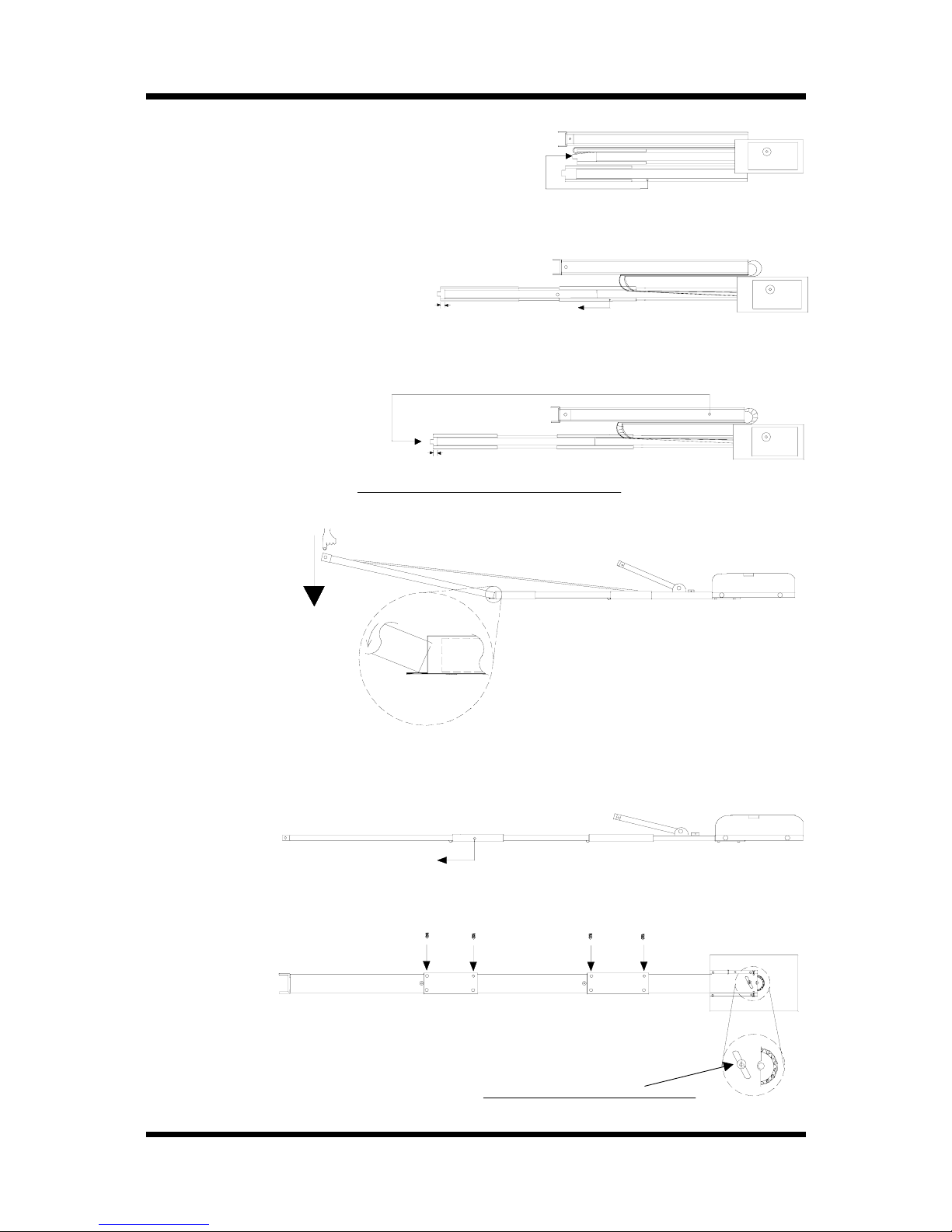
1. You have unpacked your UK garage door
opener and have it in front of you.
2. Take the part designated with a 2 in the drawing,
and place it in front. Slide the C-profile coupling
piece over part 2 all the way home.
Part 1 and part 2 are now connected
with one another.
3. When mounting part 3, make absolutely
sure not to twist the chain!
Chain
Leave the C-profile coupling piece so that
protrudes about 10mm (0,4 ") past part 2. Then
take part 3 and set it in the C-profile coupling
piece at an angle, inserting it from above as
shown. To tension the chain, press down on
part 3.
4. Push the C-profile coupling piece forward as far as it will go,
then screw in at least one fixing screw to secure it.
5. If you want to impart even greater stability to your C-profile rail, then
screw in all of the supplied fixing screws.
The chain has been pretensioned in the factory; do
not change the chain tension!
Preassembly
Installation Instruction UK - Page 2
1
2
3
12
3
1
2
3
2
3
1
Let the C-profile
coupling piece
p
rotrude(by10mm
)
To
tension
chain
2
3
10 mm
10 mm
Page 3
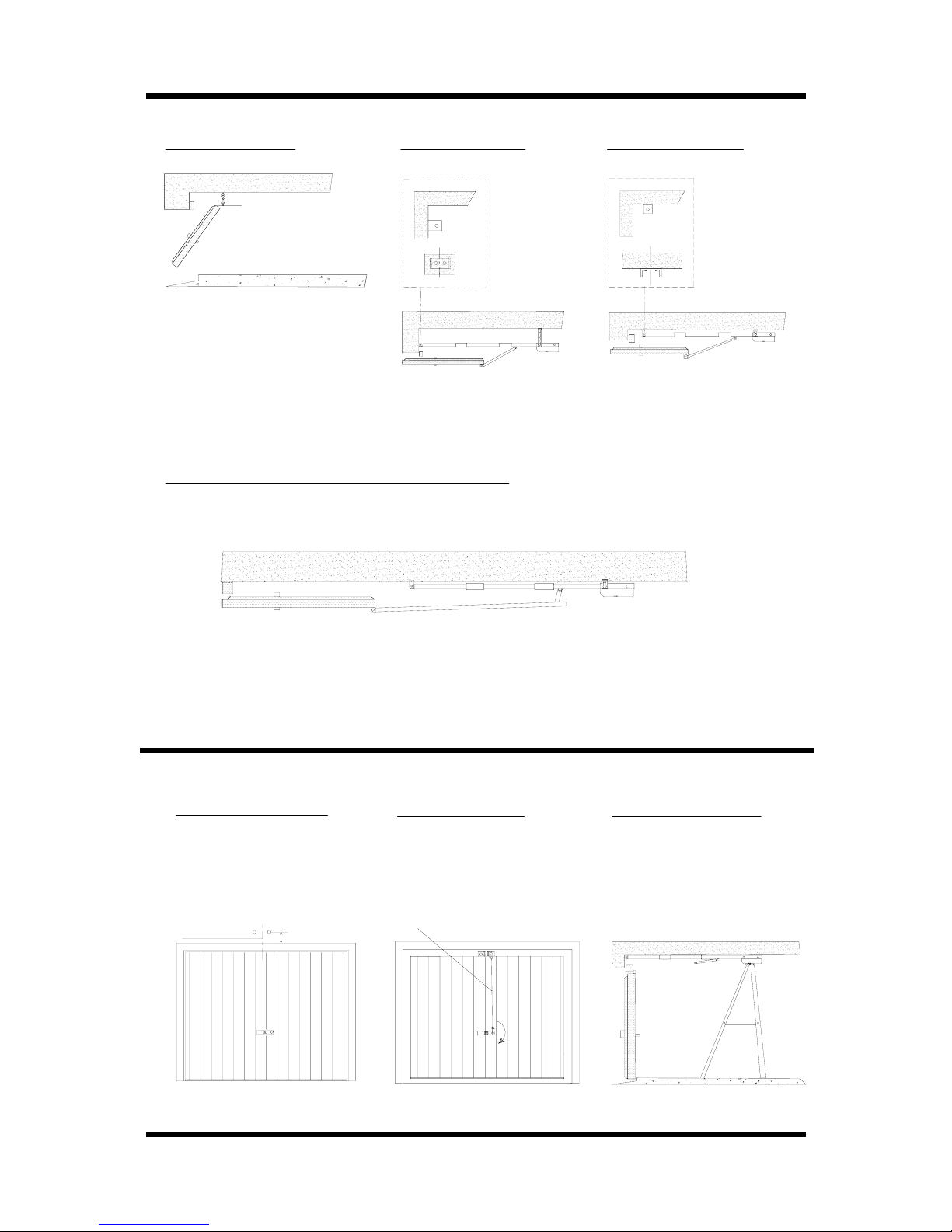
Minimum headroom Installation on lintel Installation on ceiling
When mounting as shown in the
diagrams at right, make sure there
are at least 35 mm (1,37") of headroom between the ceiling and highest
point reached by the door while pivoting.
Installation without the minimum headroom of 35 mm
If there is not enough room to leave the minimum headroom of 35 mm, then the opener
must be mounted with a drawbar extension (available as an optional extra).
Extension piece
Procedure
Mounting
Installation Instruction UK - Page 3
35 mm
Minimum headroom
Lintel attachment angle
Mount the lintel attachement
angle above the middle of
your garage door, either on
the lintel or on the ceiling.
Make sure to leave the
required minimum headroom.
Emergency release
The Bowden pull-wire for the
emergency release must be
attached to the garage door.
Handle in such a way that it is
pulled downwards when the
handle is turned.
Attaching the drive unit
When attaching the drive unit
to the ceiling, we recommend
placing a ladder underneath
it.
Page 4

Endschaltereinstellung
Installation Instruction UK - Page 4
"OPENING"
limit-switch actuator
Your UK garage door opener automatically stops when one
of the red limit-switch actuators trips a limit switch
(in either "closing" or "opening" dirction).
Adjust the limit switches
by hand
"Opening"
direction
Please set the limit-switch
actuator for the "opening"
direction so that the door
comes to a halt about 30
mm (1,2") before its final
resting position
"Closing"
direction
Please set the limit-switch
actuator for the "closing"
direction so that the door
lightly touches the door
frame when closed.
"CLOSING"
limit-switch
"CLOSING"
limit switch actuator
"OPENING"
limit switch
Speed switch S1
Your UK 80 or UK 100 garage door opener lets you
choose from among two different speeds.
This is done with the aid of switch S1, which is on
the
top of the drive unit. The following two speeds are
preset in the factory:
1: 13 cm (4,7")/sec. (brown cable, 28 V AC)
2: 9 cm (3,5")/sec. (blue cable, 22 V AC)
You can easyly select either of these speeds by
changing the position of the speed switch.
Setting of the speed (UK 80 and UK 100 only)
Page 5

Electronics
Installation Instruction UK - Page 5
Please unplug power-supply cable before changing any connection!
The most important connections for the installation are:
Test-button for running the operator without remote-control: 11
First push: OPENING, second push: STOP, third push: CLOSING and so on.
Regulation of force:
CLOSING force: 9
OPENING force: 10
The force for either OPENING or CLOSING can be adjusted seperately.
Adjustement of the force: turn down the forces to their minimum. When you let the mounted operator run, it
then probably will switch off because it cannot move the garage door. Then rise the force steadily till it is high
enough to move the door. Do not adjust the forces on their maximum
if not necessary for door movement! The excess force will increase the damage on objects or persons being
accidentially hit by the garage door (if there is no external security connected)!
(Turning to the right rises the force, turning to the left decreases the force).
Connection for external push-button or key switch: C and D
Connection
for external security: A and B
Here you can connect a light barrier or a security contact. Do not remove the bridge between A and B if you
do not connect an external security! This is a NC-contact: if the bridge is removed, the operator will not
work.
Do not put any electrical tension from outside onto the electric board!
That would damage the circuit board heavily!
Connections:
1 : Lighting (blue)
2 : " (blue)
UK 80+UK 100:
3 : 22or 28 V AC, dependend on speed
setting
4 : "
UK 60:
3: 24 V AC
4: "
5 : Motor (black or green)
6 : " (red)
7 : Transformer (brown or white)
8 : " (green/yellow)
9 : CLOSING Force
10 : OPENING For ce
11 : Test-button (OPEN-STOP-CLOSE)
12 : Connection for the limit-switch MBX cable
13 : Primary fuse, 230 V AC, T 1 Amp
14 : Secondary fuse, T 6,3 Amp
A : Connection for external security (light
barriere), potential free
B : Connection for external security (light
barriere)
C : Connection for push-button, potential free
D: "
Page 6

Extension (optional)
An extension piece can be ordered to extend the
length of the C-profile rail up to 4,15 m (163").
Mounting the extension piece:
If your garage door opener has already been
preassembled, start by loosening the fixing screws
holding the front C-profile coupling piece in place.
slide the coupling piece back far enough so that it
protrudes by about 10 mm (see page 2, step 3).
Now take the tension off the chain by lifting the
front section of the C-profile rail (see page 2).
Open the chain on the chain tensioner. Insert
the extension chain and the C-profile rail extension piece.
Now continue as described on page 2.
Each extension kit includes:
- C-profile rail
- C-profile coupling piece
- 1 chain
- 1 chain link (master link)
- 4 threaded studs
Technical Data UK
Installation Instruction UK - Page 6
17 kg17 kg17 kgWeight, excl. packaging
19 kg19 kg19 kgWeight, incl. packaging
35 mm35 mm35 mmSpace required above door
approx. 2 min.approx. 2 min.approx. 2 min.Lighting duration
24 V, E14, max. 15 Watt 24 V, E14, max. 15 Watt 24 V, E14, max. 15 Watt Lighting
230V - 22/28V AC230V - 22/28V AC230V - 24V ACMain transformer
190-260 volts AC190-260 volts AC190-260 volts ACPower supply
5-95 kg adjustable5-75 kg adjustable5-55 kg adjustableOPEN/CLOSE force
3205 mm3205 mm3205 mmOverall length
8 cm per sec.9 cm per sec.-Operating speed slow
11 cm per sec.13 cm per sec.13 cm per sec.Operating speed fast
self-locking, 95 kgself-locking, 75 kgself-locking, 55 kgGears
24 V- low noise24 V- low noise24 V- low noiseDC motor
UK 100UK 80UK 60Data
Standard specification:
UK garage door opener, complete with mounting components, remote control system, transmitter, receiver, pushbutton unit
and packaging.
We reserve the right to make technical changes without notice.
Page 7

Remote Control Set
Installation Instruction UK - Page 7
Receiver
Codification-block
The receiver is fixed on the electric board. Besides
you find the codification block with 12 switches.
1-channel
hand-transmitters
Opening a 1-channel hand-transmitter as shown on
the drawing besides, you will find the same
codification block as the one for the receiver. You
may adjust all 12 switches as you like. Be careful
not to put all switches onto ON or OFF and make
sure you have the same code on both,
hand-transmitter and receiver. (The ON written on
the codification block shall help you to orientate).
More-channel
hand-transmitters (up to
4-channel)
Inside a more-channel hand-transmitter you will find
a codification block with 10 switches. On these you
may adjust any code you like. Make sure not to put
all switches onto ON or OFF.
The switches 1 to 10 on the receiver-codification
block must be adjusted like in your
hand-transmitter.
The subscription on the bottom of this page shows
you how to use the switches 11 and 12 on the
receivers codification block. For example you might
have two or three operators you wish to control with
only one hand-transmitter. In that case you will
have to use a two- or a three-channel
hand-transmitter. The codification of the switches 1
to 10 will be the same in all components (all the
receivers and all the hand-transmitters). Only the
switches 11 and 12 will be adjusted different on
each of the used receivers, dependent on which
button of your hand-transmitter you want to use for
which operator.
Transmission
range:
There is no fixed rule how to reach the maximum
transmission range. The range will be influenced
by:
- building-materials used for the garage
- surroundings of the garage
- area
In some garages it might not even be necessary to
unroll the antenna, in others you might not reach a
high distance without extensioning the antenna. Try
putting the antenna into different directions (into the
back, into the front, to the side of the garage) and
choose the position where the result is the best.
Avoid putting the antenna into contact with
metal or electrical wires.
Trying the remote-control set make sure not to be
too close to your operator (a minimum distance of 4
m should be held) otherwise you might overpower
the receiver, what will not cause a damage but the
remote-control just might not work on that
short distance!
Button 2
Button 3 Button 4Button 1
Adjustment of the switches 11 and 12:
Codification block
Batterie
Page 8

~Power failure?
~Disconnect and connect receiver.
~Is the door stuck because of snow and ice?
~Check the lines and the connections of the push-button switch.
~Is there water in the push-button switch or in the key operated switch?
~Check the line of the push-button switch.
~Does the push-button switch work, when the receiver is disconnected? If so, your
transmitter is defective.
~Check the accordance of the transmitter and the receiver code.
~Displace the antenna of the receiver. Avoid each metal contact (reduces the range).
~Check the battery of the transmitter
~Change the code of your remote control (of transmitter and receiver).
~Disconnect the receiver or remove the transmitter battery. Use your push-button switch
only. If this solves the problem, your sender may be defective.
~Disconnect the push-button switch and use your transmitter only. If this solves the
problem, the push-button switch or the line of the push-button switch may be defective.
~Is the limit switch "OPEN" correctly set?
~Is the door jamming while opening?
~Unlock the carriage manually (make the door running well). Lubrificate and oil the pivotal
points of the door.
~Increase the power for the OPENING direction
~Is the limit switch "CLOSE" correctly set?
~Is the door jamming while closing?
~Unlock the carriage manually (make the door running well). Lubrificate and oil the pivotal
points of the door.
~Increase the power for the CLOSING direction
~Is the limit switch "CLOSE" correctly set? If not, your opener switches off under
pressure. In this case the chain is under tension and therefore the emergency release
can hardly be unlocked. Make sure that the limit switch is correctly set, otherwise your
opener can be damaged.
~Replace the bulb (24 V, E14, max. 15 Watt)
~Unlock the carriage of the opener. Move the door manually and make sure that the door
is well balanced (must come to a stop at each position).
~The spring tension is too high or there is even a spring fracture.
~The door is jamming.
~The carriage is unlocked. If you want to lock it, open the door, but not completely, and
let the opener run. The carriage locks automatically.
~Unlock the carriage with the help of the emergency relese and open the door manually.
(If you have a garage where you can only enter from outside: Unlock the door with the
key and turn the door-handle, then your opener will be unlocked.
If you have a garage where you can also enter from inside: pull at the Bowden cable
hanging from your carriage.)
Problems? No problem....
The opener reacts on
the transmitter but not
on the push-button
switch.
The emergency release
doesn´t work very well.
The door opens and
closes without order.
The door doesn´t close
completely and opens
again.
The opener doesn´t
react on the transmitter
nor on the push-button
switch.
The opener works, but
the door doesn´t move.
The opener reacts on
the push-button switch
but not on the
transmitter
The opener doesn´t
work because of a
power failure.
The motor is buzzing
but the door doesn´t
move.
The opener isn´t
running well.
The door doesn´t open
completely.
The light doesn´t go on.
Page 9

Problems? No problem....
 Loading...