

Page 1
Installation Instructions
Procedure for fitting a Seip TM80 electric operator to a horizontally tracked one-piece up & over garage door
Tools you will require:
A 13mm spanner, 10mm & 13mm hex sockets & wrench,
pair of side cutters or combination pliers, hammer, pencil,
No.2 Pozidrive screwdriver, electric drill, 5mm HSS drill,
5.5mm masonry drill, a ‘pump action oilcan’ filled with car
engine oil, step ladder.
Before Getting Started
1/ A minimum clearance of 35mm is required between
the top of the door and the ceiling/beams for the C-rail
track.
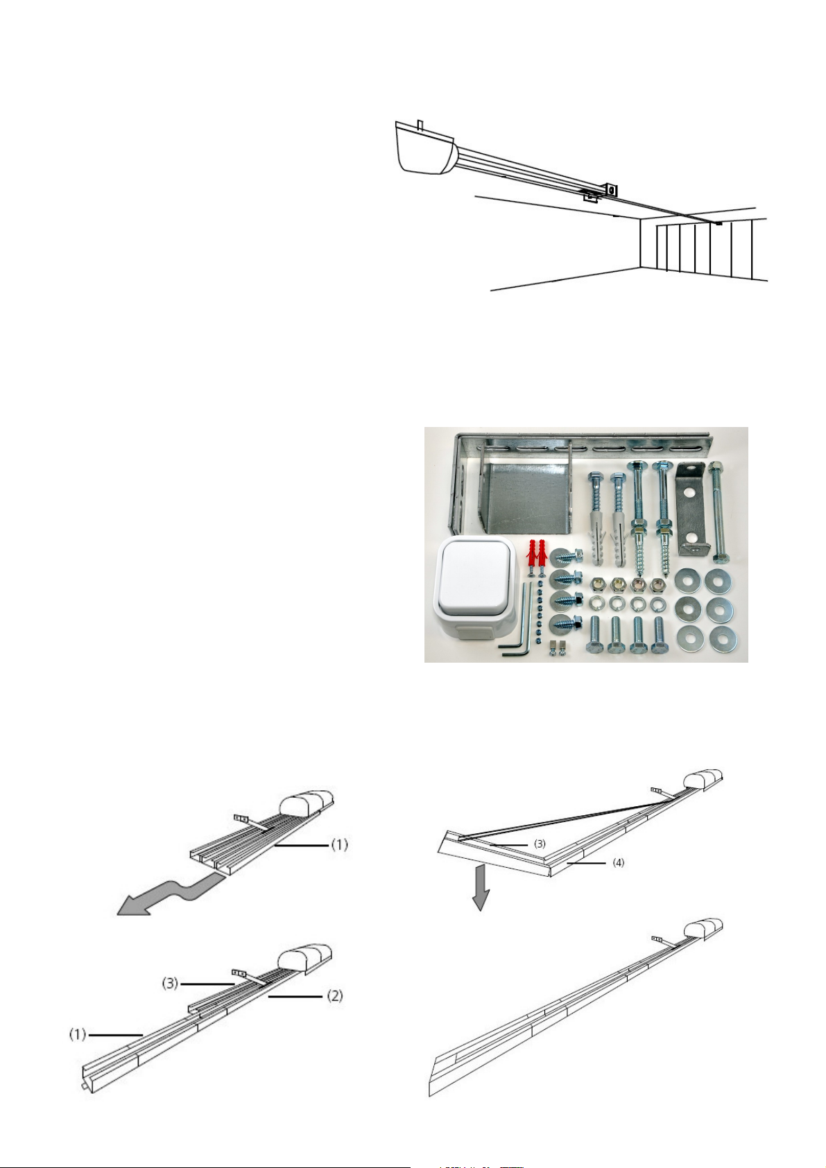
Note: if you have insufficient clearance for the track, the
operator can be mounted on the ceiling to the rear of the
garage and connected to the door with an extended door
arm as shown on right
2/ If the door is higher than 2.4mtrs a C-rail track & chain extension kit may be required
3/ Lubricate all the pivot bearings & both roller spindles on the door support gear with oil and check the operation of the door
with particular attention to correct spring balance, a correctly adjusted door should balance like a pair of weighing scales when
the door is half open, if your door sinks heavily when stopped at this position the spring adjustments (on both sides) should be
increased. The door should move freely through the opening without rubbing on the frame and should close snugly onto the
frame at the bottom corners.
Contents of the installation hardware pack
One pair of motor support brackets, door header bracket & bolt, a
selection of fixing screws, washers & masonry plugs, a small
screwdriver, Allen key, bag containing eight track securing grubscrews & two emergency-release cable clamps, wall mounted
pushbutton switch & fixing screws. Units supplied by Amourelle
Ltd also include1Mtr of red P.V.C. sleeving for the emergency
manual release cable and a label for the door with instructions
detailing how to operate the door in the event of a power failure.
Unpacking and assembling the track
1/ Lay the operator on the floor with the motor head to the right
hand side, slide part (1) out and fully engage it with the C-rail
coupling piece (2)
2/ Slide section (3) out in front of part (1) keeping the chain free of twists
3/ Slide the C-rail coupling piece (4) out 25mm beyond the end of section (1) raise section (3) up at an angle as shown (below
right) and press it down to stretch the chain and engage it with the C-rail coupling piece (4)
and slide the C-rail coupling piece forward to cover the joint
4/ Turn the unit over and fit the M5 grub screws into the eight tapped holes and tighten with the Allen key provided
The chain is pre-tensioned and will not require any adjustment, your Seip operator is now ready for installation.
(contact us for details)
(the procedure for fitting to sectional type up & over doors is similar)
- Seip electric door operators
Page 1 of 4
Page 2
Mounting The Operator
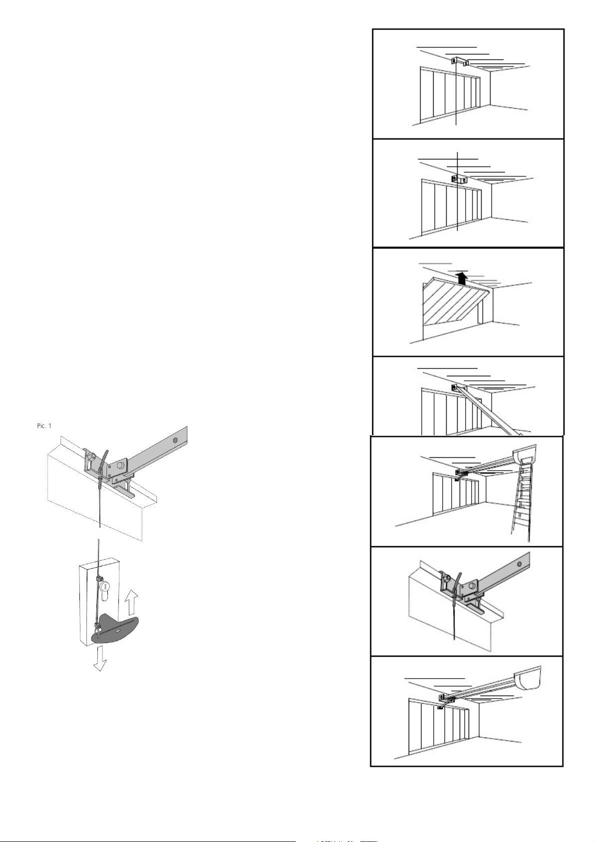
1/ Close the door, measure the centre of the door and mark this position on the
door and the frame header. Note: check that the door-frame header is securely
fixed at the centre and make good with additional fixings if necessary.
2/ Fix the C-rail fixing bracket to the lintel, door header, or ceiling, as shown in
Fig 1 or 2 The ideal position is 50 - 100mm above the top edge of the door.
3/ Place a carton on the floor to protect the motor casing and attach the C-rail to
the front fixing bracket as shown in Fig 4
4/ Raise the motor head and support it either by using a strap from the beams or
a pair of steps as in sketch as shown in Fig 5
5/ Open the door and align the C-rail track with the centre of the door and adjust
the motor height to give a clearance of approx 30mm to 60mm between the C-rail
track and the face of the door. The motor head may now be fixed to the ceiling
with the brackets provided. (for model TM80 refer fig 3 on page 7 of the
manufacturers installation manual for fixing details) Note: If you have a high
ceiling it may be necessary to extend the motor fixing brackets.
6/ Disengage the black sliding trolley from the chain drive (by pulling the manual
release cable forward) and slide the trolley along the track towards the door.
7/ Fix the door arm bracket to the top edge of the door as shown below. Four M6
self tapping screws & washers are provided for use on steel doors. For timber or
G.R.P. doors use M8 x 40mm coach screws & washers.
8/ Disable the original manual latching system on the door, (the motor will
automatically secure the door at the top when closed)
Note: Our Securi-Dor AP2000 multi-point locking system may be fitted to provide
additional security by automatically engaging the door's original manual latches
when closed.
Emergency Release Device
If your garage door is the only entrance you must provide a means of
opening the garage door from outside in the event of power failure.
Seip operators feature a Bowden cable operated emergency door-release device
to allow manual operation in case of power failure, this can be operated either
from inside the garage, or from outside by means of the original locking door
handle if you have a "vault type" garage (no personal access door)
To enable the door to be released from
outside with a key the emergency
release cable should be connected to
the original locking door handle as
follows:
Connect the emergency release cable
to the back of the door's original handle
so that when the handle is unlocked and
turned from outside it pulls the cable
downwards. The sketch (Pic1) is only a
guide as door handles vary according to
the make of door.
Note: Do not leave the garage and
close the door until you have
tested the operation of the
emergency release from outside.
Get someone to test for correct
operation of the handle & cable etc.
while you are inside.
If your garage has a personal
entrance door it is not necessary to
connect the emergency release cable
to the door handle as above
Note: we do not recommend using the red pull toggle supplied by the factory.
We recommend that you fit 4mm red sleeving (supplied) over the cable instead
and secure the end of the emergency release cable to a fixed point on the back
of the door garage, this will enable manual operation from inside by pulling the
cable.
Fig 1
Fig 2
Fig 3
Fig 4
Fig 5
Fig 6
Fig 7
Page 2 of 4
Page 3

Mounting the wall mounted push button control switch
Pry out the switch rocker place from the backplate and
fix the backplate to the wall near the exit of your garage
at a minimum height of 1.5 mtrs. using the two
No 6 x 30mm screws & wall plugs provided.
Wall control switch
Mains Power Supply
1/ Your Seip door operator will require a 13A mains power point positioned
on the ceiling approx. 3.4mts back from the centre of the door frame.
(alternatively a 13A extension lead can be run from an existing point)
Limit-Switch Adjustment and Automatic Force Measurement
Please refer to the manufacturers installation manual enclosed
with your specific operator model for this procedure
Important Note
Unless the above procedure has been completed the unit will only run for a few seconds before stopping
Final Check
After completing the adjustment procedure, open and close the door making sure that the motor stops at least
30mm before the door reaches the door support track end buffers when open, and stops without applying excessive
pressure against the door frame when closed. (test the operation of the
manual release device because
if too much
force is applied against the door frame when the door is closed it will result in excessive force being require to
operate the
Testing The Safety Stop Sensitivity
Stand outside and start the door in the CLOSE direction, when half closed, restrain the door by hand and check that the motor
stops and reverses when hand pressure is applied to the lower edge of the door, a similar test should be carried out during the
OPEN phase to make sure the door stops when hand pressure is applied to the lower edge of the door
Attach the yellow safety warning label (supplied) in a prominent position on the back of the door
The Installation is now complete ! - Relax & enjoy many years of effortless luxury & convenience !
Security
The motor will automatically lock the door at the top when closed. If physical security is an important issue Amourelle's unique
Securi-Dor multi-point locking system can be fitted to enhance your security by automatically engaging additional side latches on
the door when closed.
Optional infra-red break-beam safety detector kit
This device can be fitted to your Seip garage door operator for added safety
manual release device)
These instructions have been compiled by Amourelle and should
be used in conjunction with the manufacturers installation instructions
For further technical advice phone: 01384 900 264
Amourelle Products, Unit 16 James Scott Rd, Halesowen,
West Midlands B63 2QT - www.Garage-Door-Automation.co.uk
The Garage Door Spares & Automation Specialists
Page 3 of 4
Page 4

OPERATING INSTRUCTIONS
Seip TM80 Electric Garage Door Operator
Press the wall mounted push-button or remote control key-fob button for half a second to start the
motor, the courtesy light will illuminate automatically and extinguish a few minutes after the motor was
last used. further use of the push-button can be used to stop the door during motion, and change the
direction of travel.
IN THE EVENT OF A POWER FAILURE
Your door can be released from the motor and operated manually by pulling the RED MANUAL
RELEASE CORD inside the garage while pushing the door out from the bottom, detailed instructions will
be found on a label on the back of the door. If your garage has no alternative pedestrian access the
original locking door handle can allow manual operation of your door from outside. The key to this
locking handle should be labelled "garage door emergency release key" and kept in a safe place. (not in
the garage)
OPERATING THE UNIT AFTER MANUAL OPERATION DURING POWER FAILURE
To restore normal motorised operation, close the door then start the motor.
MAINTENANCE
The remote control transmitters are powered by a battery with a life expectancy of two years, the mini
keyfob takes two CR1616 "coin" type cells, four button midi keyfob uses one CR2032 battery. The
courtesy lamp is an E14 screw fitting 45mm golf-ball type bulb, easily accessible behind the plastic
diffuser cover. (40 Watt Max) Your Seip electric operator should not require any maintenance for ten
years but in order to keep the installation in good working order the moving parts on the door should be
lubricated at 12 month intervals.
REGISTERING AN ADDITIONAL KEYFOB TRANSMITTER
Take an existing registered keyfob & use it to close the door, then within five seconds of closing the
door, hold both keyfob buttons down simultaneously for five seconds until the courtesy lamp starts
flashing, (on a four channel midi keyfob use the upper two buttons) Now take the new keyfob and press
the button you wish to use to operate the door, the light will stop flashing when the new fob is registered,
repeat as above for further keyfobs.
YOUR GUARANTEE
The manufacturers guarantee on your Seip electric door operator covers all parts for five years. This
guarantee does not cover light bulbs or batteries. If you have any problems with your Seip electric door
operator, please contact Amourelle for assistance.
Amourelle Products, Unit 16 James Scott Rd, Halesowen,
West Midlands B63 2QT - phone: 01384 900 264
www.Garage-Door-Automation.co.uk
The Garage Door Spares & Automation Specialists
Page 4 of 4
 Loading...