

Page 1
OPERATING
MODELS
INSTRUCTIONS
S^^-6/W-6F
SKM-26
SEIKO
SEWING
TOKYO,
MACHINE
JAPAN
CO.,
LTD
Page 2
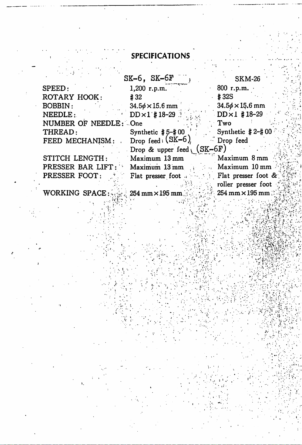
SPECIFICATIONS
SPEED:
ROTARY
BOBBIN:
NEEDLE:
NUMBER
THREAD:
FEED
STITCH
PRESSER
PRESSER
WORKING
MECHANISM:
HOOK:
OF
NEEDLE
LENGTH
BAR
FOOT:
SPACE:;.v
:
LIFT:
SK-6,
1,200
#32
34.50x15.6
DDxl #
SK-6P
r.p.m.
18-29
: One •/
Synthetic
.
Drop
feed1(SK~6)^
Drop&upper
Maximum
Maximum
Flat
presser foot i
.
254mmX195mm.:
-vi:-
mm
#5-#
13
13
J
00
feedv,
mm
mm
800
•
#32S
34.50X15.6
^
DDxl
V
Two
Synthetic
•
Drop
(SK—6P)
Maximum
Maximum
Flat
roller presser foot
254
SKM-26 \
r.p.m.
• ; /
mm
#18-29 '
#2-#00
'
feed
8 mm
10
presser foot & . :
mm
X195
mm
mm
VV
-
••••
:•
"f^
[
i
• I :
!
..
Page 3
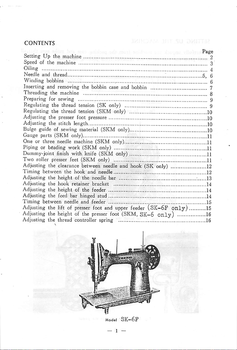
CONTENTS
Page
Setting Up the machine 2
Speed
of the machine 3
Oiling 4
Needle
Winding bobbins g
Inserting and removing the bobbin case and bobbin 7
Threading the machine 8
Preparing for sewing 9
Regulating the thread tension (SK only) 9
Regulating the thread tension (SKM only) 10
Adjusting the presser foot pressure 10
Adjusting the stitch length 10
Bulge guide of sewing material
Gauge parts (SKM only) H
One or three needle machine (SKM only) 11
Piping or beading
Dummy-joint finish with, knife
Two
Adjusting the clearance between
Timing
Adjusting
Adjusting
Adjusting
Adjusting the feed bar hinged stud 14
Timing
Adjusting
Adjusting
Adjusting the thread controller spring 16
and
thread
(SKM
work
(SKM
roller presser feet (SKM only) 11
only) 11
(SKM
needle
between
the
the
the
between
the
the
the
hook and needle 12
height of
hook
height
needle
lift
of
the
retainer
of
the
and
presser
heightofthe
needle
bracket
feeder 14
feeder
foot
presser
only) 10
only) 11
and hook (SK only) 12
bar
and
upper
foot
feeder
(SKM,
(SK-6P
SK—6
only)
only)
5^
; 13
14
15
15
16
g
Model
SK—6P
- 1 —
Page 4
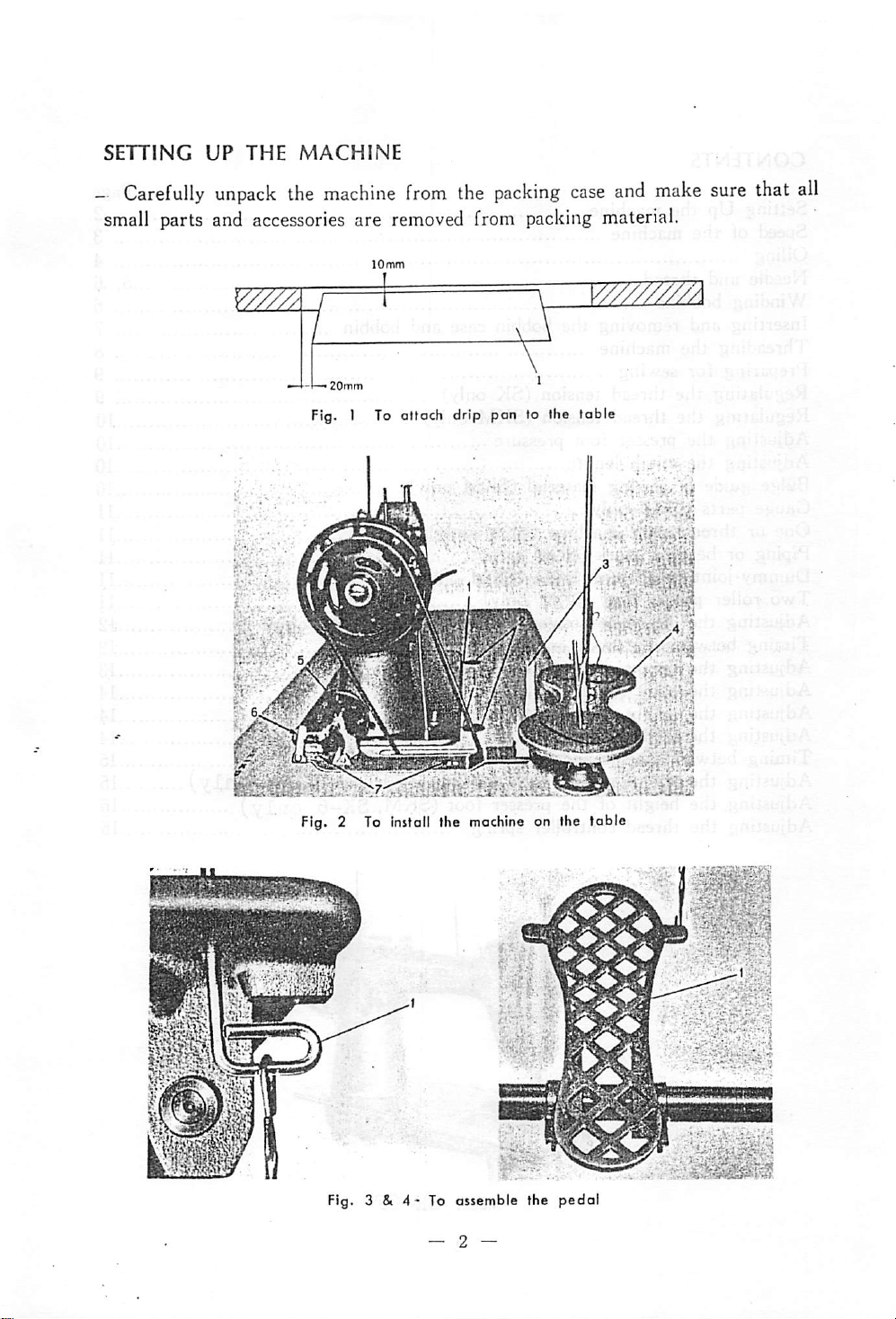
ase
and
ma
ig material.
Fig. 2 To Install the
Fig. 3 &
4'
To assemble the pedal
machine
A
on the table
Page 5
ti.'v30''~40
ii'
s.
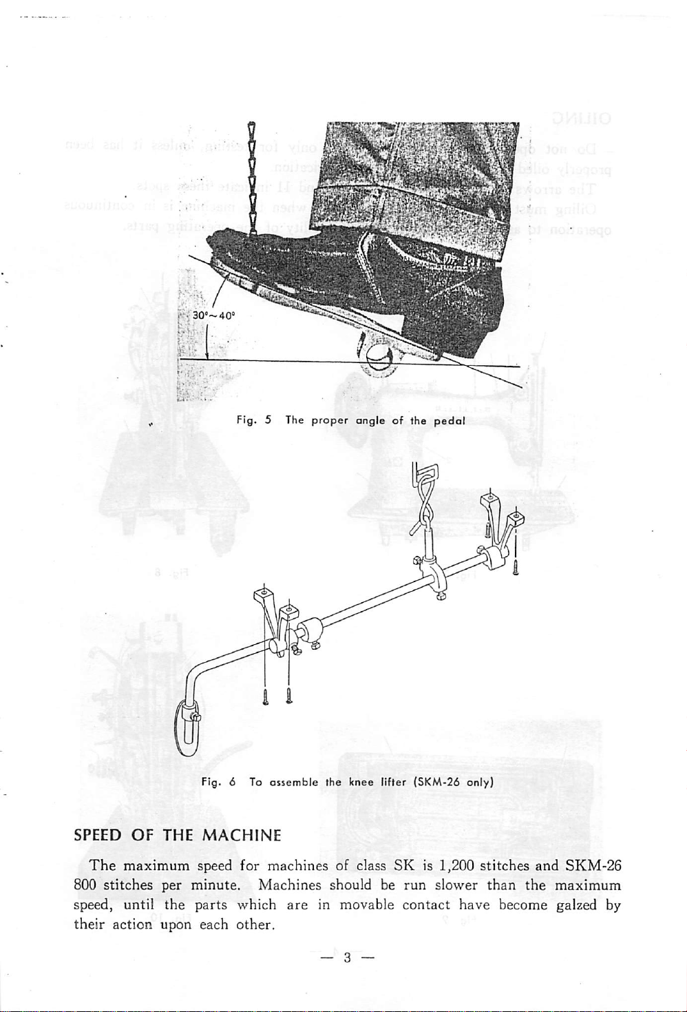
Fig. 5 The
proper
angle of the
pedal
i
Fig. 6 To ossemble the knee lifter (SKM-26 only)
SPEED
The
800
OF
maximum
stitches
THE
per
MACHINE
speed
minute.
for
machines
Machines
of class
should be
SK
run
is 1,200
slower
stitches
than
and
the
SKM-26
maximum
speed, until the parts which are in movable contact have become galzed by
their
action upon each
other.
Page 6
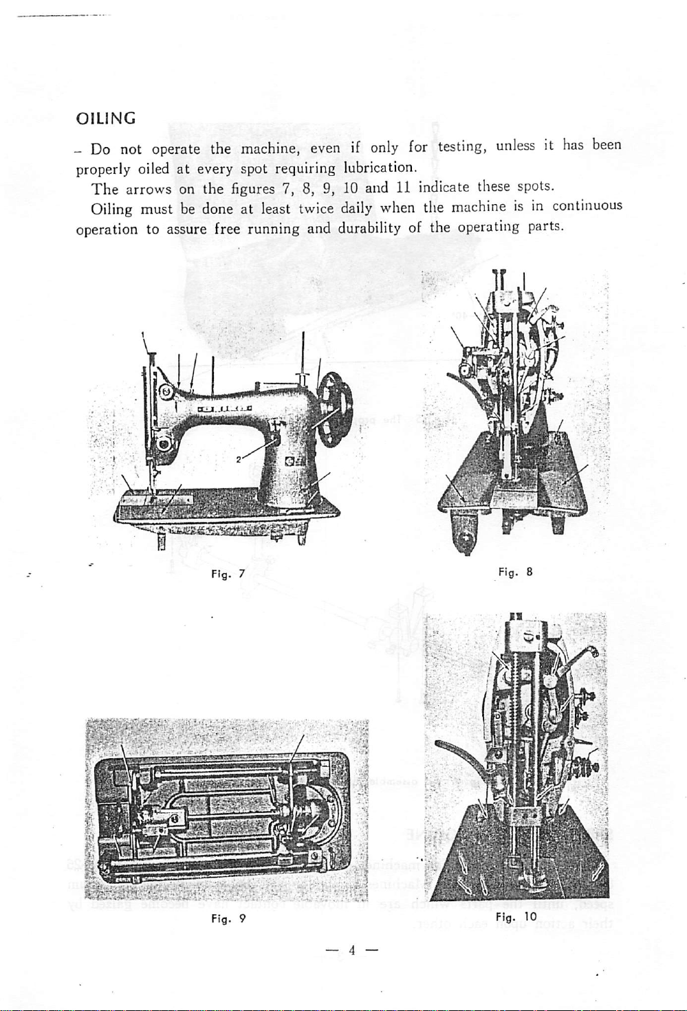
OILING
-
Do
not
operate
properly oiled at every spot requiring lubrication.
The arrows on the
Oiling
operation
must
to
assure
the
figures
be
doneatleast
free
machine,
7, 8, 9, 10 and
running
evenifonly
twice
and
daily
durability
11
when
for
testing,
indicate
the
of the
unlessithas
these
spots.
machineisin
operating
parts.
ir I
i
rV....
mESp
been
continuous
lol
n
®!5
Page 7

Fig. 11
NEEDLE
The
The
needle eye, determines
To
bar rise to its highest point, loosen
(SK Fig. 12, SKM-26 Fig.
machine is set up to
thickness of the sewing thread, which must pass freely through the
insert the needle, turn the machine pulley toward you, until
use^DDxl
the
size of the needle.
13)
in size ranging from 18 to 29.
the
the
needle set screw (2) and put the needle
needle
up into the needle bar as far as it will go, with the long groove of the needle
toward the left (SK), or toward you (SKM).
screw
securely.
Then,
tighten the needle set
Page 8

THREAD
twist
needle,
/ \ ^
J
F'g*
The
bobbin can be wound with either left or right twist thread.
\^
of
thread
fingersofyour
counterclockwise.
If it will twist tighter, it has a left twist.
If it unravels, it has a right twist.
to test for twist, hold a length
between
hands.
threadisto
thumbs
Turn
be
and
the
used
index
thread
for
WINDING BOBBINS (Figs. 2 and 15)
The
bobbin winder is mounted on the table top with its pulley (5, Fig. 2)
in front of the driving belt so that the
pulley
will separate from the belt after
the bobbin has been wound with suflicieiit thread, push the bobbin on the
bobbin spindle (3 Fig. 15) as far as it will go.
Pass the thread from the thread stand downward through the eye (1, Fig. 15)
in
the
tension
Then,
the
thread
tion several times around the bobbin. Push bobbin winder lever (4, Fig. 15)
downward until the wheel (5) contacts the drive belt and
After
the bobbin is filled with thread, release will cause the wheel to disen
bracket.
between
forward
and
around the back of the tension discs (2
toward
the
bobbin
and
wind
from
Fig.
15) hring
belowinclockwise
start
the machine.
direc
gage from the belt and winding will stop. Cut the thread and remove the
bobbin from the winder spindle.
The
adjusting screw (A, Fig. 15) can be turned in or out to increase or
decrease
If
the
amount
the
thread does not wind evenly on bobbins, loosen
of
the
thread
wound
on
the
bobbin.
the
screw (B, Fig. 15)
and move the bracket to the right or left as may berequired and tighten the screw.
Fig. 15
— 6 —
Page 9

INSERTING
AND
REMOVING
THE
BOBBIN
CASE
AND
BOBBIN
Turn
Push the
bobbin case (2,
Pull up the latch (1, Fig. 17) and lift
To
the balance wheel until the needle is above the needle plate.
retainer
insert a full bobbin, raise
(1, Fig. 16) to
Fig.
16).
the
the
left
latch
like the figure 16, and remove the
the
bobbin from the bobbin case.
in center of the bobbin case, and
place the bobbin on the center post of the bobbin case.
Be sure
Pull the thread into the
that
the
thread
draws
cut
(4,
out
Fig.
from
18) in
tho
bobbin from left to
the
edge of
right.
the
bobbin case, and
from you under the tension spring (5, Fig. 18). Then, pass its end from
back through the hole (6, Fig. 18) in
the
bobbin case.
Finally, push down the latch to retain the bobbin in position.
the
Page 10

Fig. 20
• 1
THREADING
(SK
only)
B 1
\vWk
1
JB
j
-^5
HBj
;
six
«•
^
B
S'i
B '
Vyy'SE-
-^B
Bi
"Jspi '
^PiSwwBfWMiiii.i
Fig.
21
Fig.
21
right through the eye of the needle, leaving an end of the thread about 10cm long.
,
J(
^8
^1^3
||
,2 discs (4), over
I
JiS^\
r^[i
\g
*
5 n
j.
,1
'KB
Raise
and
above
down
tween
spring
ulator
from right to left through the hole in
the
the thread guide (9), through
bar thread guide (10), then from left to
THREADING
(SKM
Raise
above
and
der
through
left
lever (8),
the
into
the
bet^veen
from
the
(5),
(6),
take
only)
the
between
from
the
slack
the
through
THE
MACHINE
needle
the
thread
the
tension
under
up
up
lever
needle
right
thread
guard
the
down
bar
to
thread into the hole (1)
guide
(2)
the
retaining
right,
the
through
THE
the
to left
under
disc
(4),
slack
the
(8),
down
MACHINE
bar
to
retaining
around
the
spring (5), un-
regulator
(7),
from
holeinthe
through
its
highest
and
from
discs
(3),
and
be-
over
the
thread
guard
its
the
reg-
(7),
through
the
needle
highest
discs
(3),
the
ten-
(6),
up
right
take
to
up
thread
Fig.
22
you, leaving the end of the thread about 10 cm long.
through
then through
the
needle clamp hole (11),
the
eye of
the
needle
Page 11

PREPARING
FOR
SEWING
With
of
slack
Turn
until
the
left
hand
hold
the
needle thread, leaving it quite
from
the
end
to
the
the hand pulley toward you
the
needle
moves
down
the
needle.
and
end
up
again to its highest position, thus
catching the under thread.
Then,
pull the end of the needle
thread you are holding, then the
bobbin tliread will be
brought
up
with it through the needle hole in
the
needle plate.
TENSION
OF
THE
BOBBIN THREAD (Fig. 18)
If it is necessary to
the
tension
on
the
alter
bobbin
thread, slightly turn the screw
(7) to
or
to
the
turn
decrease
the
right
screw
it.
to increase it
to
the
left
mf
Fig. 23
~ Perfect stitching.
- Tight tension of needle
Loose
tension
Fig. 24
of
needle
thread.
thread.
REGULATING
THE
THREAD
TENSIONS (SK only)
For ordinary stitching, the tension of the
upper and lower threads should be equal so
that
both
If
the
tension on
threads
areinthe
either
centerofthe
thread
is
goods.
stronger
than on the other, imperfect stitching will
be
the
result.
A
correct
stitch
can
be usually
obtained
by adjusting the tension on the needle thread.
To
increase the tension,
nut
(1) to
it
to
If
discs
the
tension of
the,thumb
the
pressure against
the
right,
the
left.
the
thread is found to slip in the tension
without
turning
the
retaining discs by
nut (3) to the right and decrease
the
ing slightly the thumb
or to decrease
them,
turn
the thumb
it,
turn
slightly increase
turning
tension discs by turn
nut
(1) to the left.
— 9 —
Fig. 25
Page 12

Fig. 26
7*
REGULATING
TENSION
The
(SKM
thread tensions of upper thread
THE
only)
THREAD
(a) and lower thread (b) should be
equal
k
1.
Correct
tension
2. Tight tension of needle thread
3. Tight tension of bobbin thread
ADJUSTING THE TENSION OF THE
UPPER
The
THREAD
serrated nut (6) controls the tension of two
upper threads. To increase the tension, turn the
nut to right, or to left to decrease it.
ADJUSTING
LOWER
See
Fig.
27
ADJUSTING THE
The
pressure of
To
increase the pressure, turn it to the right and to the left to decrease the pressure.
ADJUSTING THE STITCH
Turn
regulating
Continue
the
balance wheel toward you, at
lever
the
PRESSER
the
presser foot is regulated by the screw (1).
(2)
until
pressure on
LENGTH
it snaps
the
lever and
the
FOOT
into
THE
THREAD
instructions
PRESSURE
(Fig. 7)
the
same time pressing on
the
feed
driving
turn
the
TENSION OF
for
SK
(Fig. 7)
mechanism.
balance wheel
THE
machines.
either
the
to or
feed
from
you until the travel of the feed is such as to give the required length of stitch.
BBmmm
^^^81
11,111
|||i||||iii|||i||ii^
IS
'
^
V;
the
bulge
SEWING
Normally,
comes
plate.
screw
ward
varied according to the sewing
purpose.
to
To
adjust this, loosen
(2)
the
The
shape of
GUIDE
OF
MATERIAL
the
and
arrow
edge of
center
move
the
of
the
direction.
the
guide
guide
the
guide
needle
the
can
(1)
set
to
be
—
10
—
Page 13

GAUGE
PARTS
(SKM
only)
There are three kinds of gauge parts (needle clamps) as 3.5 mm 4.8 mm and
7.5 mm, according to your purpore, replace it to the required size.
ONE
moccasin stitch and the other needle makes decorative coarse stitching.
clamp, needle plate,
OR
THREE
One needle machine is used for decorative coarse
On three needle machine, either
Three
These stitcliings can be made by replacing
needle
NEEDLE
machine
and
MACHINE (SKM only)
the
can also be used
feeder.
PIPING
A piping work requires a special needle plate
having
out
for
for
OR
a hole
the
right
only
the
BEADING
through
work.
or
the
straight
left side (two needles) make
decorative
respective presser foot, needle
which a coad is comming
stitching.
WORK
coarse
(SKM only)
stitching.
Fig. 31
DUMMY-JOINT
A
knife
pers.
fitted on the presser foot makes dummj'-joint finish on
For
this work, knife and special presser foot with groove are required.
: I
t!
FINISH
WITH
allow
KNIFE
roller
the
(SKM only)
the
shoe up
PRESSERS
roller pressers employing ball bearings
curve
stitching
(SKM
successfully.
only)
Page 14

ADJUSTING
After
position so
mm,
eye.
I
|||,„
adjusting
that
when
Then,
THE CLEARANCE BETWEEN NEEDLE
the
center
the
clearance
the
hook point comes to 3.5 mm
tighten
three
of the needle to
between
screws (2).
III
I
the
the
needle
from
'Pq loosen the screw (4), at first
remove
ratchet (1,
mil
Fig.
33
AND
hook point, adjust the liook
and
hook
the
upper end of the needle
bushing
bottom
the
of
bobbin
Fig.
HOOK
(SK
only)
becomes 0.1 to
(3)tofit
the
hook
39).
like
case
snugly
retainer
0.2
the
THE
TIMING
BETWEEN
HOOK AND
NEEDLE
(SK
only)
Loosen the hook set screws (2, Fig. 33), turn the hand pulley toward you
until
the
1-
THE
.
Loosen
- from its lowest point.
—
-—
I
^ L
^ L
3.8mm
T
C—shaft
Fig.
34
TIMING
BETWEEN
HOOK
the hook set screws, turn the
needle
The
dimension
lines (1) and (2) is 3.8
standard.
Bring
tbe
by
screws
Be
tween
the hook point (2,
center
moving
(2,
Fig.
sure
that
the
surface of
bushing
move
smoothly.
AND
NEEDLE
balance
wheel
bar
raises
between
mm,
of
the
needle
the
hook
and
33).
thereisno
the
and
the
hook
(SKM
only)
toward you until the
to
3.8
the
two
use it as a
Fig.
(1,
Fig.
tighten
clearance
hook driving
but
needle bar raises to 3.8 mm from its lowest position.
Bring
(3),
the needle and hook point
the
hook
point
then tighten the
(1, Fig.
hOok
36)
screws,
0.1mm
to the center
at the
to 0.2 mm.
same
between
time,
set the
two
needles
clearance
(2)
between
mm
basic
35) to
35)
three
be
they
and
—
12
—
Page 15

ADJUSTING THE HEIGHT OF THE
This
should be made
determined.
needle to the hook point (refer to Fig. 35).
Turn
after
the
balance wheel
the
timing
Loosen
2
] /
asmrn-j-
^ Then, tighten the screws.
'
/"•
/
||
\ .
\I|;3.8mm
I \
\ 1 Fig.
\ • y
N.
•'
Fig.
35
eye
comestodown
When
adjust
to
fit
34)
turn
the
the hook point comes to the center of the needle
or not when the bottom of the needle bar bush-
ing
fits
NEEDLE
between the needle
toward
two
down
the
the
needle
the
bottomofthe
and the
hand
to the
BAR
(SK only)
and
hoolc has been
you so as to fit
screws (1, Fig. 37), adjust the needle
so that the
3.5
mm
needle
barisat
bar
bushing
,needle
basic
line
pulley
basic
toward
line
(2,
the
upper
endof the
from
its
up
(1, Fig.
you,
Fig.
center
the
hook
lowest
and
downsoas
bar
bushing
34).
confirm
24).
of the
needle
point,
position,
(3,
Further,
whether
Fig. 37
after
the timing between the
determined.
needle to
the
hook point.
.38),
adjust the needle
Fig. 38
Ftg.
36
ADJUSTING THE HEIGHT OF THE
NEEDLE BAR (SKM only)
This
should be made
needle
the
bar up or down so that the upper end of the
eye comes to 3.5 mm down from the hook point,
at the same time, the two needles must be parallel.
Then,
and
hook
has
been
Turn
Loosen the screws (1, Fig.
the balance wheel toward you so as to fit
center
of
the
left
tighten the screw (1, Fig. 38).
—
13
needle
Page 16

ASSEMBLING
THE
Fig.
HOOK
39
RETAINER
BRACKET
This
must be done
the
clearance
hook.
Let
the retaining
sufficiently, but not to bend,
hook (3) without
tighten
Excess
makes
unnecessary
between
the
screw (4) securely.
contact
after
the
spring
any
clearance, theri
between
wear
and
adjusting
needle
(2) contact
with
the
noise.
and
the
two
ADJUSTING
Adjust
the
feed dog to its highest position.
Fig.
ADIUSTING
the
40
THE
feed
THE
HEIGHT
motion
FEED
OF
THE
FEEDER
to
the
maximum
and
turn
the
balance
^Loose^
Fig. 41
BAR
HINGED
When
is not parallel with the surface of
loosen
get
the
the
its parallel, then tighten
STUD
feed dog is at its highest position, if it
stud
screws (1)
and
the
wheel
the^
the
turn
the
screws.
to
raise
screws
needle plate,
stud
(2) to
Fig.
42
14
—
Page 17

TIMING
The correct timing is as follows:
Adjust
ward
of
the
reaches to the needle plate.
To
five
centric adjusting
V U-, M» y
VJ"
you,
feeder
adjust
oil
v.
BETWEEN
the
feeding
after
become
this,
the
feed
NEEDLE
motiontothe
the
feed
equal
pull
open
eccentric
flange
dog
has
height to the
the
adjusting
(4) for the adjustment.
AND
finished
top
FEEDER
maximum
its
surface
cover
flange
(1),
coupling
and
turn
feeding
of the
loosen
(2)
the
motion
needle
three
and
move
balance
and
plate,
screws
the
wheel
when
the
(3)
feed
to
teeth
needle
out
ec
of
Fig. 43
ADJUSTING
The
adjustmentofthe
forth travel is made so that the teeth of the feeder rise to the highest point
at the
feed lifting
driving
any clearance axialy.
ADJUSTING
UPPER
the presser foot and upper feed dog.
of
the
(3), then tighten the screw (2).
middle
Loosen
To
make
direction
Be
suretotighten
The thickness of the material sewn should control the height of the lift of
It
should
Push
the
the
presser
upper
two
cam
its
FEED
normally
presser
surface
THE
position,
screws
(6).
up
and
UP
AND
when
(5)
down
DOWN
up
and
feeding
and
adjustitagainst
travel
andtomakeitslower,
THE
DOG
foot
bar
of
screw
LIFT
be
(3)
the
OF
just
lifter
to
needle
pushing
THE
high
(i)'up,
the
needle
TRAVEL
down
plate
travelofthe
travelisthe largest.
faster,
the
PRESSER
enough
loosen
turn
screw
and
(4)
turn
the
against
FOOT AND
for
clearance
the
adjust
and
the
the
cam
screw
the
Fig. 44
OF
THE
FEEDER
(SK-6F,.SKM
feeder
main
the
bottom
against
shaft
by
feed
lifting
toward
the
measure13mm
opposite
rod
(7)
of the material.
(2),
fit
the
of
the
only)
its
back
and
moving
cam
the
toward
direction.
nottomake
needle
presser
hole
between
foot
—
15
-
Page 18

Fig.
S M
m
45
.h
Lower
lift to be always equal height by lossing
(6) and moving the upper feeder (5) up and down,
when
When
move
crank
raise
knock pin.
Then
justed according to
the
presser
turning
the
driving
the
the
the
raising
position of the lifting presser .bar bell
position of
lift
bar
balance wheel.
the
lift of the upper feed dog,
cam
shaft
the
of
the
presser foot (3)
the
lifter
and
so adjust
(7)
and
the bell
presser foot (5) by
lift of
the
upper feeder (5).
the
crank
must
the
be ad
both
screw
(8)
the
ADJUSTING
I'-
•
h• I
I
Fig.
ADJUSTING
(SK,
Fig.
25,
THE
46
THE
SKM
HEIGHT
Raise the presser bar lifter (1) and so adjust the
I
gCSr
fMYfpresser
THREAD
Fig. 27)
between
^
OF
THE
PRESSER
the
bottom
adjust
this,
presser
bar
(5)
upordown,
CONTROLLER
FOOT
of
the
loosen
the
foottothe
SPRING
(SKM,
presser
screw
foot
(4),
fit
SK-6
(SKM-26)
(2)
the
needlebymoving
then
tighten
the
only)
and
the
needle
the_
screw.
Normally, the thread controller spring (4) should hold slack of the .upper
thread until the needle reaches to the goods, and it should pause.
To
adjust this, loosen the screw (5) and adjust it by turning the thread take
up
spring
To
screw stud (7) with a screw driver and turn the serrated nut to the right, to
lighten the tension, turn to the left. Then, tighten the tension screw stud.
regulator
strengthen the tension of the controller spring, loosen slightly the tension
(6).
—
16
—
Page 19

y!
•.
.->•:•:>';••••:-V
•
.f.
•
A,.
••
I?:. ^.!
iJlltWiSiCSi-'iSw
• *. I ••••
•••.
•...'.
• • .'•
!•
•
•
••••
•
::
••
•• ; "'•,=
•
I •'•"••"^•*
••
. • • • ••. .-»••. •..•,'••.• • ..
•;.•..••••••..,•
'•
: -•<•' . • •
-v"' / A ••«•;;<•;.• -.••••••
•;
: •
I'::.
• • •0'- r•..•
••
.:
. ' V-.-. • .. r
/•.
:
:•*
/ •
•
!^-•'•c^r-yy:y'
;'YV
•":.
"i",
. . • V . • V' .
"n.
;•••'••: 'V'C"
•• •
'•'
•'••..•
"••
• ""t-. '. 'I-•
^ '•
.••
••• >• . •• •.'1-
Cl"
'*
•
".
'-"'K
•
V
••.•
1 "v
..
••••'•
-^"h-
,1;
.•..•.
••••'. '
•.••
' " .
••'*.
' ' •• • • ' ; •
. i . ••.
'.
••.•(>•
,••».••
(•'
' ; ' V .•••
' •" '
-••
•:'•~
^ •
•'i'l
•••
•••-.
;j
.:•''
J.
.
••
Page 20

\
• • .•',
. "
• •. . • • .
• . •. ^
'
••
.
• • \ :• •
•• • :
•.-/-i:-V-m;
.. ; ' • i
=
. V-.. ; v < • y
i. • !
•yy-
. ' •
•.
•••
- r.• •'.
•'r- '
^ ". i -•'
'••••:
• ' i
•
.''•••
• ; • • • • • •
^ . ;
— • .••••••V:
':
- • '.
•y-'.
.
. •
.a:;..
•<•;?
'••
•..
• •
••
•','•.••
••
. . • • •••. • ;
•• •
•f'.i/
V;
^ : •. • ^ ; v;
V^;
f"'
•li
V•
--St;v'
->:•
•.'•
.
'••
(yyyy
••••••••:'
";vM-
'":
•:?
Ki.''
•;
- y
'Irr/-••
•.'••);
• •' v. y. • •: .i •" " • •. ' : . • ' • •
; f••; v . ; ^ ^ "
••'•:'•••••..•''••
..
•v:-:.-..y .
v^y•.••'
• .=;y
I.-"..' ' . . •;•-/•".
••"
••
'. 1'- • '.•
-.••
•h'-yy
yy••
••r • .•
^ -V • • ?'V ' ' ' ' ^
«<.
c- • "
-r.,
kW'-.vI'.v-;''.'-"'4
'
'•'.•'?••''•'••••••.'
'••••
' .•.•.
"-y-y
•.
'"y-•
.•
'-y'-;
••
.•
•?.
y y y-
"A
. . • . .
I?-•••
•••
t
••••
••••'
• '• • •'•••' ' *
- ' •• • ' • .•
;'.
.1 •!'•••
i!.
•
VC-f
;••.•
••.•
y
. ' • '
• •. V • •
v.•.
..•..•••
' 1 ' • •
r-
•'-
i.'-
."
•>•
^...
•
r • ^ •
v. •
'
•
=;
'••
V-..
•'
;
-t
'
•y
i."'
Printed in Japai
 Loading...