

Page 1
i
PW, LPW
PW-6,6B,7,7B,8,8B,8M,8BM,26,26B,27,27B,28.28B
LPW-6.6B,7,7B.8,8B.8M,8BM,26,26B.27,27B.28,28B
LPW-6L.6BL,7L,7BL,8L.8BL,26L,26BL,27L,27BL,28L,28BL
OPERATOR'S
GUIDE
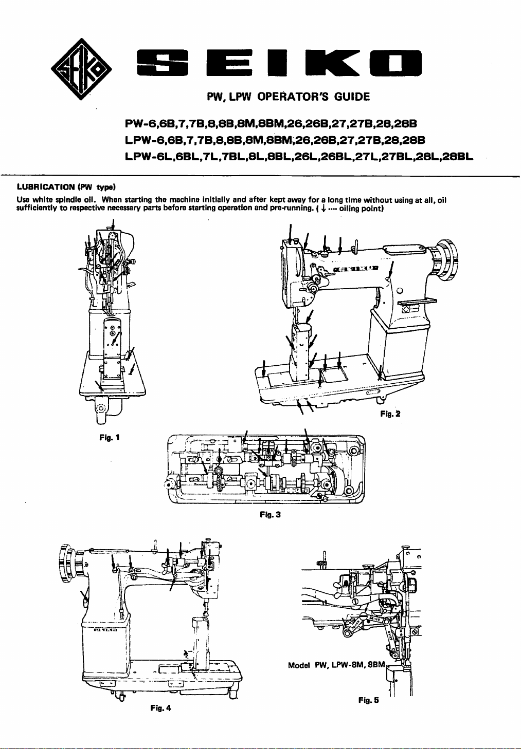
LUBRICATION (PW
Use
white
sufficiently to respective necessary parts before starting operation and pre-running. ( i ...• oiling point)
spindle oil. When starting
type)
the
machine initially
and
after
kept
away
for
a long
time
without
usingatall, oil
Fig.
3
Model PW, LPW-8M, 8BM
Fig.
Fig.4
5
Page 2
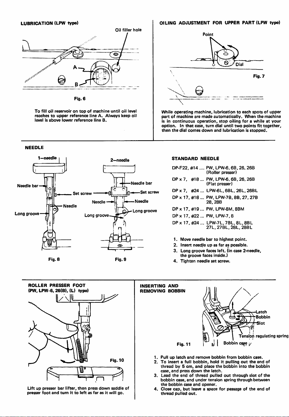
LUBRICATION (LPW
To
fill
oil
reachestoupper
levelisabove
NEEDLE
reservoirontopofmachine
lower
type)
Fig.
reference
reference
6
lineA.Always
line
OILING ADJUSTMENT FOR UPPER PART (LPW type)
Oil
filler
hole
"V
until
oil
level
keep
8.
oil
While
operating
partofmachine
is in
continuous
option.Inthat
then
the
dial
machine,
are
case,
comes
Point
made
operation,
turn
down
lubricationtoeach
automatically.
stop
dial
until
and
lubricationisstopped.
When
oiling
forawhileatyour
two
points
Fig.
7
spotsofupper
the
machine
fit
together,
Needle
Long
1—needle
L J
J L
bar
groove
ROLLER
(PW,
LPW-6,26(B),
F
Fig.
8
PRESSER
k:^
Needle
(L)
Set
FOOT
type)
screw
Long
_ J
['
Needle
groove
2—needle
Fig.
)
Needle
bar
Qm Set screw
Needle
Long
groove
9
INSERTING
REMOVING
STANDARD
DP-F22,#14.
DP
X
7.
DPx
7.
DPx
17,
DPx
17.
DPx
17,
DPx
17.
1.
Move
2.
Insert
NEEDLE
..
PW,
(Roller
..
PW,
#18
(Flat
#24
..
LPW-6L.6BL,26L,26BL
..
PW.
#18
28.288
..
PW.
#19
..
PW,
#22
#24
LPW-7L.78L.8L,88L
27L,278L,28L.
needle
bartohighest
needileupas
LPW-6.6B,26,
presser)
LPW-6,
68,
presser)
LPW-7B.
LPW-8M,
LPW-7,8
88.
88M
point.
faraspossible.
26,268
27.
288L
3. Long groove faces left, (in case 2-needle,
the
groove faces inside.)
4.
Tighten
needle
set
screw.
AND
BOBBIN
26B
278
Latch
Bobbin
Slot
Bobbin
bobbin
from
holditpulling
the
bobbin
latch.
pulled
out
tension
spring
for
passageofthe
through
through
Liftuppresser
presser
foot
and
bar
lifter,
tumitto
then
press
leftasfar
down
as it will
Fig.
saddle
10
go.
Fig.
11
Pulluplatch
To
insertafull
threadby5
case,
Lead
3.
bobbin
the
of
Close
thread
bobbin
and
press
the
endofthread
case,
cap,
but
pulled
and
remove
bobbin,
cm,
and
down
and
under
case
and
leaveaspace
out.
place
the
opener.
Tensibh regulating spring
c^^
y
bobbin
case.
out
the
end
bobbin
slotofthe
between
end
of
of
into
the
Page 3

WINDING
BOBBIN
1. Place a bobbin on the bobbin winder spindle as far as possible.
2.
Lead
3. Press down lever for drive then start machine. Pulley will be
threadasshownbyFig.12
disengaged
thread.
from
V-belt
and
wind
automatically
Pulley
several
after
timesonbobbin.
bobbin
fillsupwith
Serrated
o Winding
Adjustablebyserrated
nut
strength:
nut.
THREADING
1-NEEDLE
Lever
'>1 '..•cTN
Screw
(2)
o
Winding
Adjustablebyscrew
NEEDLE
II
amount:
(2).
LPW
Fig.
o Raise needle
thread
oTHREAD
Fig.
13
1—needle
2—needle
Screw
o
Uneven
winding:
Adjustablebyloosen
windertorightorto
12
bartohighest
stand
the
following numerical
NEEDLE
from
lefttoright
from
insidetooutside
(1)
point
screw
left
•
Fig.
and
order
(1)
and
PW
15
lead
thread
1(A)~11(K).
move
from
THREAD
ataiatatate'
Tight
terisionofneedle
Loose
tensionofneedle
Perfect
Fig.
TENSION
stitching
16
Needle
^ thread
^Material
Bobbin
thread
thread
thread
Less
NEEDLE
To
adjust,
Fig.
turn
THREAD
Serrated
17
serrated
nut
nut
' \
Tension
To
adjust,
BOBBIN
Fig.
THREAD
regulating
18
turn
adjusting
h V ,
it'More'^
screw
screw
Page 4

ADJUSTING
PRESSER
(Comiwund
machina
FEET
feed
only)
LIFT
with
OF
ALTERNATING
walking
foot
PW
type
TO
REGULATE
PRESSER
LPW
FOOT
type
PRESSURE
More
^ i 1
^
Less
To
adjust,
and
stud
assembly
ADJUSTING
Pressing
Then
Hold
rearward so
markonarm.
down
plunger
the
plunger-down
Fig.
19
loosen
wing
along
STITCH
buttonA,turn
will
enter
that'desired
Then,
Wing
nut
slot.
LENGTH
into
and
release
number
More
Less
nut
and
move
link,
Number
(stitches/inch)
Fig.
pulley
notchinfeeding
turn
the
slowly
pulley
either
on pulley may come at
plunger.
22
toward
mechanism.
forward
you.
A
Lever
23
lever ps
i @
far
Fig.
21
Fig.
© I
20
The
pressureonthe
while
still
sufficienttoinsure
REVERSE
(only
wHh reverse
To
or
as it will
STITCHING
reverse
go.
material
stitch
stitching,
shouldbeas
correct
feeding.
mechanism.)
iff
press
down
lightaspossible,
evT—
Fig.
the
RE-ENGAGE
(except
PW.
SAFETY
LPW-6,6B,
CLUTCH
26,26B)
MECHANISM
TRIMMER
(8M,BBM
type)
Lever
m
Fig.
24
Fig.
Tokyo
26
CO.,LTD.
111-6534,
Japan
1.
Remove
in
hook.Donot
2. Pressing
to
re-engage
any
foreign
safety
use
clutch.
buttonBand
matter
which
any
sharp-edged
turn
pulley rearward slowly
may
have lodged
tools.
SEIKO
11-3,
Tel:81-3-3872-6173--4{Ovsiseas Group) Fax:81-3-3873-6596
SEWING
imado
1-chome,
MACHINE
Taito-ku,
When
loosen
Screw
Fig.
26
replacementofknife,
two
screws.
 Loading...