

Seiko LTP1245R-C384-E, LTP1245S-C384-E, LTP1245T-S384-E, LTP1245U-C384-E Technical Reference
Page 1

LTP1245X-X384-E
LINE THERMAL PRINTER MECHANISM
TECHNICAL REFERENCE
U00085320001
Seiko Instruments Inc.
Page 2

LTP1245X-X384-E LINE THERMAL PRINTER MECHANISM TECHNICAL REFERENCE
Document Number U00085320001
First Edition December 2003
Second Edition March 2005
Copyright © 2003, 2005 by Seiko Instruments Inc.
All rights reserved.
Seiko Instruments Inc. (SII) has prepared this manual for use by SII personnel, licensees, and customers.
The information contained herein is the property of SII and shall not be reproduced in whole or in part without
the prior written approval of SII.
SII reserves the right to make changes without notice to the specifications and materials contained herein
and shall not be responsible for any damages (including consequential) caused by reliance on the materials
presented, including but not limited to typographical, arithmetic, or listing errors.
SII is a trademark of Seiko Instruments Inc.
Page 3

PREFACE
This reference manual describes the specifications and basic operating procedures for the LTP1245 (for
RoHS) Line Thermal Printer Mechanism.
For the LTP1245 (RoHS supporting), four models are available:
• LTP1245R-C384-E
• LTP1245S-C384-E
• LTP1245T-S384-E
• LTP1245U-S384-E
In this reference manual, the information mentioned as LTP1245 is common to all models
unless otherwise noted, and if the information is different depending on the model, specific
model name is mentioned clearly.
Chapter 1 “Precautions” describes safety, design and operational precautions. Read it thoroughly before
designing so that you are able to use the LTP1245 properly.
SII has not investigated the intellectual property rights of the sample circuits included in this manual. Fully
investigate the intellectual property rights of these circuits before using.
Also, when designing the circuits based on the sample circuits in this reference manual, use them after
thorough verification.
iii
Page 4

iv
Page 5

TABLE OF CONTENTS
Section Page
CHAPTER 1 PRECAUTIONS
1.1 SAFETY PRECAUTIONS ............................................................................................ 1-1
1.2 DESIGN AND HANDLING PRECAUTIONS................................................................ 1-2
1.2.1 Design Precautions......................................................................................... 1-2
1.2.2 Handling Precautions...................................................................................... 1-3
1.2.3 Precautions on Discarding .............................................................................. 1-4
CHAPTER 2 FEATURES
CHAPTER 3 SPECIFICATIONS
3.1 GENERAL SPECIFICATIONS..................................................................................... 3-1
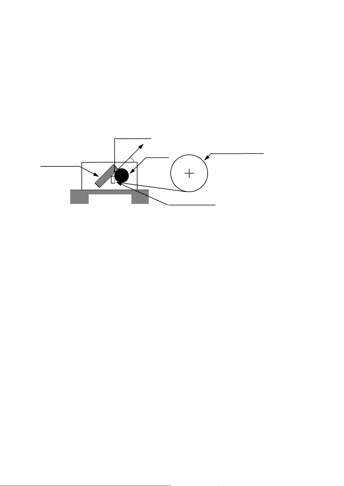
3.2 HEAT ELEMENT DIMENSIONS.................................................................................. 3-3
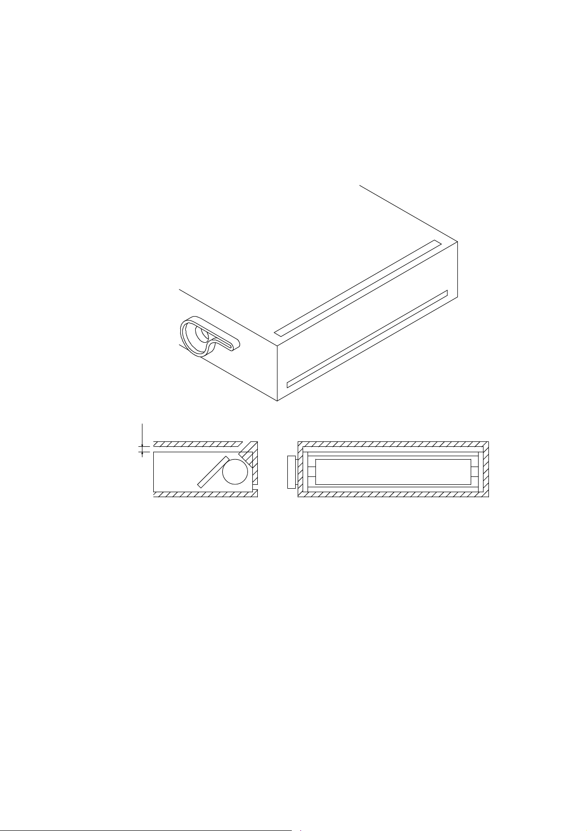
3.3 PAPER FEED CHARACTERISTICS............................................................................ 3-4
3.4 STEP MOTOR CHARACTERISTICS........................................................................... 3-5
3.4.1 Motor Drive Circuit........................................................................................... 3-6
3.4.2 Motor Timing.................................................................................................... 3-8
3.4.3 Precautions for Driving the Motor.................................................................... 3-10
3.5 THERMAL HEAD ......................................................................................................... 3-14
3.5.1 Structure of the Thermal Head........................................................................ 3-14
3.5.2 Printed Position of the Data............................................................................. 3-16
3.5.3 Head Resistance............................................................................................. 3-17
3.5.4 Head Voltage................................................................................................... 3-17
3.5.5 Peak Current ................................................................................................... 3-17
3.5.6 Thermal Head Electrical Characteristics......................................................... 3-18
3.5.7 Timing Chart.................................................................................................... 3-19
3.6 CONTROLLING THE HEAD ACTIVATION (DST) PULSE WIDTH............................. 3-20
3.6.1 Calculation of the Head Activation Pulse Width.............................................. 3-20
3.6.2 Calculation of the Applied Energy................................................................... 3-20
3.6.3 Adjustment of the Head Activation Voltage..................................................... 3-21
3.6.4 Adjustment of the Head Resistance................................................................ 3-21
3.6.5 Determination of Activation Pause Time and Activation Pulse Period............ 3-22
3.6.6 Head Activation Pulse Term Coefficient.......................................................... 3-22
3.6.7 Calculation Sample for the Head Activation Pulse Width ............................... 3-23
3.6.8 Thermistor Resistance .................................................................................... 3-24
3.6.9 How to Print Using 2-ply Thermal Paper......................................................... 3-25
3.6.10 Detecting Abnormal Temperatures of the Thermal Head............................... 3-26
3.7 HEAD-UP/PAPER DETECTOR................................................................................... 3-27
3.7.1 General Specifications .................................................................................... 3-27
3.7.2 Sample External Circuit................................................................................... 3-28
3.7.3 Automatic Paper Load..................................................................................... 3-29
3.8 Mode Code Label......................................................................................................... 3-30
v
Page 6

Section Page
CHAPTER 4 CONNECTING EXTERNAL CIRCUITS
4.1 THERMAL HEAD CONTROL TERMINALS................................................................. 4-2
4.2 MOTOR AND DETECTOR TERMINALS..................................................................... 4-3
CHAPTER 5 DRIVE METHOD
5.1 THERMAL HEAD DRIVE TIMING................................................................................ 5-1
5.2 MOTOR DRIVE TIMING .............................................................................................. 5-2
CHAPTER 6 HOUSING DESIGN GUIDE
6.1 SECURING THE PRINTER ......................................................................................... 6-1
6.1.1 Printer Mounting Method................................................................................. 6-1
6.1.2 Precautions for Securing the Printer............................................................... 6-1
6.2 LAYOUT OF PRINTER AND PAPER .......................................................................... 6-2
6.3 WHERE TO MOUNT THE PAPER HOLDER.............................................................. 6-2
6.4 WHERE TO MOUNT THE PAPER CUTTER............................................................... 6-2
6.5 OUTER CASING STRUCTURE................................................................................... 6-3
CHAPTER 7 APPEARANCE AND DIMENSIONS
CHAPTER 8 LOADING/UNLOADING PAPER AND HEAD CLEANING
8.1 LOADING/UNLOADING PAPER PRECAUTIONS ...................................................... 8-1
8.2 HEAD CLEANING PROCEDURE AND PRECAUTIONS............................................ 8-3
CHAPTER 9 PERIPHERAL EQUIPMENT
9.1 AUTOCUTTER UNIT ................................................................................................... 9-1
9.1.1 Installation........................................................................................................ 9-2
9.1.2 Opening and Closing the Autocutter Unit........................................................ 9-3
9.1.3 Inserting Recording Paper .............................................................................. 9-4
9.1.4 Clearing Paper Jams....................................................................................... 9-4
9.1.5 Hints for Use.................................................................................................... 9-5
9.1.6 External View when the LTP1245 is equipped with the Autocutter................. 9-6
9.2 LTP1245 MOUNT (OP-L1245A-E)............................................................................... 9-7
9.2.1 Installation........................................................................................................ 9-7
9.2.2 OP-L1245A-E External View........................................................................... 9-8
vi
Page 7

FIGURES
Figure Page
3-1 Heat Element Dimensions............................................................................................ 3-3
3-2 Print Area...................................................................................................................... 3-3
3-3 Sample Drive Circuit (Motor)........................................................................................ 3-6
3-4 Input Voltage Signals for the Sample Drive Circuit (Motor)......................................... 3-7
3-5 Motor Start/Stop Timing (Sample Drive Circuit (Motor) )............................................. 3-8
3-6 Motor Drive Timing Chart (in use at temperature over -5°C)....................................... 3-10
3-7 Motor Drive Timing Chart (in use at temperature below -5°C)..................................... 3-11
3-8 Thermal Head Block Diagram...................................................................................... 3-15
3-9 Printed Position of the Data.......................................................................................... 3-16
3-10 Timing Chart................................................................................................................. 3-19
3-11 Thermistor Resistance vs. Temperature...................................................................... 3-24
3-12 How to Drive 2-ply Thermal Paper............................................................................... 3-25
3-13 Sample External Circuit of the Head-Up/Paper Detector............................................. 3-28
3-14 Flowchart for Automatic Paper Load............................................................................ 3-29
3-15 Model Code Label ........................................................................................................ 3-30
4-1 Thermal Head Control Terminals (FFC)....................................................................... 4-2
4-2 Motor and Detector Terminals (FPC)........................................................................... 4-3
5-1 Example of Timing Chart of the Thermal Head Driving ............................................... 5-1
5-2 Example of Motor Drive Timing Chart.......................................................................... 5-4
6-1 Paper Layout................................................................................................................ 6-2
6-2 Sample Outer Casing Structure................................................................................... 6-3
7-1 LTP1245R-C384-E Appearance and Dimensions....................................................... 7-2
7-2 LTP1245S-C384-E Appearance and Dimensions ....................................................... 7-3
7-3 LTP1245T-C384-E Appearance and Dimensions........................................................ 7-4
7-4 LTP1245U-C384-E Appearance and Dimensions....................................................... 7-5
8-1 Head Cleaning Procedure............................................................................................ 8-3
9-1 Installation .................................................................................................................... 9-2
9-2 Designing a Mount ....................................................................................................... 9-
9-3 Opening and Closing of Autocutter Unit....................................................................... 9-3
9-4 Head-up Lever Position................................................................................................ 9-3
9-5 Best Cutting Position for Efficient Paper Use............................................................... 9-5
9-6 External View when the LTP1245 is equipped with the Autocutter ............................. 9-6
9-7 LTP1245 Mount Installation.......................................................................................... 9-7
9-8 LTP1245 Mount External View (OP-L1245A-E)........................................................... 9-8
3
vii
Page 8

TABLES
Table Page
3-1 General Specifications ................................................................................................. 3-1
3-2 Sample Motor Drive Frequency................................................................................... 3-4
3-3 General Motor Specifications....................................................................................... 3-5
3-4 Excitation Sequence..................................................................................................... 3-7
3-5 Acceleration Steps ....................................................................................................... 3-13
3-6 Blocks and Activated Heat Elements........................................................................... 3-16
3-7 Head Voltage................................................................................................................ 3-17
3-8 Thermal Head Electrical Characteristics...................................................................... 3-18
3-9 Activation Pulse Width.................................................................................................. 3-23
3-10 Temperature and Corresponding Thermistor Resistance............................................ 3-25
3-11 Detector's Status and Output Signals .......................................................................... 3-27
3-12 Absolute Maximum Ratings of Detectors..................................................................... 3-27
3-13 Detectors Input / Output Conditions............................................................................. 3-28
4-1 Recommended Connectors ......................................................................................... 4-1
4-2 Thermal Head Control Terminal Assignments............................................................. 4-2
4-3 Motor and Detector Terminals Assignments................................................................ 4-3
viii
Page 9

CHAPTER
PRECAUTIONS
Read through this manual to use the printer properly.
Also, design the product taking the detailed precautions that are noted in each section into consideration.
This reference manual subjects to change without notice.
Ask the latest information of the printer to our service.
Damage due to improper handing of the printer without following the instruction described in this
reference manual will not be responsible for SII.
To use the printer safely, design the product taking the precautions described below into
consideration.
Also, attach the safety precautions to all of user's manuals to further inform the users
concerning usage safety.
1.1 SAFETY PRECAUTIONS
To use the printer safely, design the product taking the precautions described below into consideration.
Also, attach the safety precautions to all of user’s manuals, as well as place warning labels on the products
to further inform the users concerning usage safety.
Precautions to prevent the thermal head from overheating
If the thermal head heat element, which always has electricity supplied by the CPU,
malfunctions, the thermal head may overheat, causing smoke and fire.
To prevent personal injury, the printer should be controlled so that the detection of abnormal
temperatures of the thermal head is performed as described in Section 3.6.9.
Turn printer off immediately if abnormal conditions occur.
Precautions on temperature of the thermal head when handling
Design the outer case to prevent the user from being burnt by touching the thermal head and its
periphery directly due to the fact that the thermal head and its periphery are hot when printing
and remains so immediately after printing. Regarding paper insertion and head cleaning,
prepare caution descriptions in the manual stating to perform these operations after the head
temperature drops. To allow cooling, insert clearance between the head and the outer case in
designing the outer case.
Precautions regarding raising the temperatures of the motor
Give warning to prevent the user from being burnt by touching the thermal head directly due to
the fact that the motor is hot when operated and remains so immediately after operating. To
allow cooling, insert clearance between the head and the outer case in designing the outer
case.
Precautions regarding sharp edges of the printer body
The printer body and/or some parts may have some sharp edges. Design the outer case to
prevent the user from being injured by touching said sharp edges and provide warnings
concerning this.
1
1-1
Page 10

1.2 DESIGN AND HANDLING PRECAUTIONS
To maintain the initial level of performance of the LTP1245 and to prevent future problems from occurring,
observe the following precautions.
1.2.1 Design Precautions
If too much energy is applied to the thermal head, it may overheat and become damaged.
Always use the printer with the specified amount of energy.
Do not input a pulse over than 2V and 20 nsec to each signal terminal of the thermal head.
Use C-MOS IC chips (74HC240 or equivalent) for CLK, LATCH, DAT and DST signals of the
thermal head.
When turning the power on or off, always DISABLE (put in “Low” state) the DST terminals.
To prevent the thermal head from being damaged by static electricity:
• Fix the printer to the Frame Ground (FG) by the FG connection parts as shown in Figure
7-1.
• Connect the GND terminal (SG) to FG through an approximate 1 MΩ resister.
Keep the Vp power off when not printing in order to prevent the thermal head from becoming
electrically corroded.
In addition, design the printer so that the signal GND of the thermal head and the frame GND of
the printer mechanism become the same electric potential.
Make the wire resistance between the power supply and the Vp as well as GND terminals on the
thermal head controller as small as possible (below 50 mΩ). Maintain a considerable distance
from signal lines to reduce electrical interference.
Surge voltage between Vp and GND should not exceed 10 V.
As a noise countermeasure, connect the capacitor noted below between Vdd and GND pins
near the thermal head control connector.
Vp ↔ GND: approximately 10 µF
Vdd ↔ GND: approximately 1 µF
Turn on power in the following manner:
At power ON: 1) Vdd (5 V) → 2) Vp
At shut down: 1) Vp → 2) Vdd (5 V)
Always detect the outputs of the head up detectors and paper detectors. Incorrect activation of
the thermal head may reduce its longevity and the platen, and damage the thermal head and
the platen.
To prevent malfunction of the detector, design the printer so that the infrared ray is not input
around the head up detector.
1-2
Page 11

Design the outer case so that the thermal head control terminals can move after fixing to the
connector because they move 2 to 3 mm due to the up/down action of the thermal head.
Design the outer case so that it prevents the paper feed out from being caught in the platen.
If the thermal head remains in contact directly with the platen, they may stick tight each other.
When the printer is not in use, put the paper between the thermal head and platen or place the
thermal head in an upward position. If the thermal head and the platen stick tight, it is only
necessary to release the thermal head so that the problem can be avoid.
Design software that will deactivate the heat elements if the thermal head thermistor (TH)
detects a temperature higher than 80 °C (thermistor resistance RTH ≤ 2.48 kΩ), and reactivate
the heat elements when a temperature lower than 60 °C (RTH ≥ 4.46 kΩ) is detected. If the
thermal head continues to be activated at a temperature higher than 80 °C, the life of the
thermal head may be shortened significantly.
The cutting surface of the motor flange may generate discoloration and rust according to
operating condition.
This is no problem for functions, however, take it into external view consideration.
1.2.2 Handling Precautions
Incorrect handling may reduce the efficiency of the printer and cause damage. Handle the printer with the
following precautions.
Also, get an operator’s attention.
To prevent the heat elements, ICs, etc. from being damaged due to static electricity, take
measures against electrification for both machine and human before handling the printer.
Care should be taken in particular regarding the thermal head control terminals when handling.
Do not apply stress to the thermal head control terminals; otherwise connectors, FPC (Flexible
Printed Cable) and FFC (Flexible Flat Cable) for the thermal head may be damaged.
If any paper other than that specified is used, a high print quality and longevity of the thermal
head cannot be guaranteed.
Possible problems that may occur are:
• Poor printing quality due to low-sensitive paper
• Abrasion of the thermal head due to a paper surface which is too rough
• Sticking between the thermal layer of the paper and the thermal head resulting in
excessive noise when printing
• Print fading due to low print preservation
• Corroded thermal head due to poor thermal layer of the paper.
Do not activate without paper; otherwise, the platen or thermal head may become damaged.
Do not hit or scratch the surface of the thermal head with sharp or hard objects. It may become
a source of damage to the heat element.
The thermal head is pressurized at the time of delivery from the factory. Place the thermal head
in an upward position before use. The head down, neutral and head up positions can be set
with the head up/down lever.
1-3
Page 12

Connect or remove the connectors after powering off the printer.
When printing at a high print rate (black or zigzag pattern) in a low temperature or high humidity
environment, the vapor from the paper during printing may cause condensation to form on the
printer or may soil the paper itself.
Keep the thermal head away from water drops.
It may become the source of a corroded thermal head.
If condensed, power off the Vp until dried.
The LTP1245 is not a water-proof printer. Prevent contact with water and do not perform
operations with wet hands. They may become sources of damages to short circuits,
overheating and fire.
The LTP1245 is not a dust-proof printer. Use in a dusty place may cause damage to the
thermal head and cause paper feed problems.
1.2.3 Precautions on Discarding
When discarding used printers, discard them according to disposal regulations and rules of each
respective district.
1-4
Page 13

CHAPTER
2
FEATURES
The LTP1245 Line Thermal Printer Mechanism is a compact, high-speed thermal line dot printing
mechanism. It can be used with a measuring instrument and analyzer, a POS, a communication device,
or a data terminal device.
Since the LTP1245 Line Thermal Printer Mechanism can be battery driven, it can easily be mounted onto
a portable device such as a hand-held terminal.
The LTP1245 has the following features:
Uses a 5 V power supply or battery power supply
The voltage used to drive the thermal head is equal to the logic voltage, or is driven by a 5 V
single power line.
The range of operating voltage is wide, so four to six Ni-Cd batteries or Ni-MH batteries can also
be used. Two Lithium-ion batteries can be used.
Compact and light
The mechanism is compact and light: 72 mm in width, 39.5 mm in depth, 16 mm in height, and
approximately 45 g in weight.
High resolution printing
A high-density print head of 8 dots/mm produces clear and precise printing.
Longevity
The mechanism is a maintenance-free device with a long life of 50 km print length and/or 100
million pulses. (Coupling with recommended thermal paper.)
High speed printing
1
A maximum print speed of 200 dot lines per second (25 mm per second) at 5 V, 450 dot lines
per second (56.25 mm per second) at 7.2 V, and 500 dot lines per second (62.5 mm per
second) at 8.0 V is attainable.
Low current consumption
The printer can be driven on low discharge current lithium-ion batteries.
Paper loading path
2
Two systems of paper loading path are provided, curl path and straight path, and the straight
path allows thick paper to be printed.
Low noise
Thermal line dot printing is used to guarantee low-noise printing.
2-1
Page 14

Automatic paper load
The paper detector enables the LTP1245 to load paper automatically.
Paper feed knob
2
The paper feed knob for manual paper feed is optionally attached depending on the
specification. It is selectable according to the applications.
Thermal head cleaning
Move the head up lever to open position to clean the thermal head.
1
Print speed differs depending on working and environmental conditions.
2
The paper loading paths (curl path and straight path) and the presence of paper feed knob
are optionally set in the factory.
Please consult our sales representative when ordering them.
2-2
Page 15

CHAPTER
3
SPECIFICATIONS
3.1 GENERAL SPECIFICATIONS
Table 3-1 General Specifications
Item Specification
Print method Thermal dot line printing
Dots per line 384 dots
Resolution 8 dots/mm
Print width 48 mm
Maximum printing speed 200 dot lines/s (25.0 mm/s) (at 5 V)
Paper feed pitch 0.125 mm
Head temperature detection Via thermistor
Head-up detection Via photo interrupter
Out-of-paper detection Via photo interrupter
Operating voltage range
V
V
Current consumption
For driving the head (V
For driving the motor (V
For head logic (V
line (for head and motor drive)
P
line (for head logic)
dd
)
P
)
P
)
dd
450 dot lines/s (56.25 mm/s) (at 7.2 V)
500 dot lines/s (62.5 mm/s) (at 8.0 V)
4.2 V to 8.5 V
2
(equivalent to four through six Ni-Cd or Ni-MH
batteries, or two lithium-ion batteries)
4.5 V to 5.5 V
Average:
1.5 A (at 5 V), 2.2 A (at 7.2 V), 2.6 A (at 8.5 V)
Maximum:
1.6 A (at 5 V), 2.3 A (at 7.2 V), 2.7 A (at 8.5 V)
Maximum 0.46 A
Maximum 0.01 A
1
1
1
3
3
3-1
Page 16

Table 3-1 General Specifications (Continued)
Item Specification
Operating temperature range
-30°C to 70°C 4
(No codensation)
Storage temperature range
-35°C to 75°C
(No codensation)
Life span (at 25°C and rated energy)
Activation pulse resistance
Abrasion resistance
100 million pulses or more (print ratio=12.5%)
5
50 km or more (excluding damage due to an alien
substance such as rubbish)
Paper width 58 mm
0
-1
Paper feeding force 0.49 N (50 gf) or more
Paper holding force 0.78 N (80 gf) or more
Dimensions (width×depth×height) 72 × 39.5 × 16 mm (excluding head up lever)
Weight Approximately 45 g
Recommended thermal paper
6
-5°C to 50°C
• TF50KS-E2D (Normal thermal paper)
from Nippon Paper Industries
• AF50KS-E (Normal thermal paper)
from Jujo thermal Ltd.
• KT55F20 (Normal thermal paper)
from Koehler AG
• F5041 (Normal thermal paper
from
Mitsubishi Hitec Paper
• TL69KS-HG76 (label paper)
7
from Nippon Paper Industries
-30°C to 70°C
• TL51KS-R2 (High heat-resistant paper)
from Nippon Paper Industries
• TL69KS-R2 (High heat-resistant paper)
from Nippon Paper Industries
5°C to 40°C
• TW80KK-S (2-ply thermal paper)
5, 7
from Nippon Paper Industries
1
The maximum printing speed is attained, for example, in the following case:
Driving voltage 8.0V, head temperature over 10°C, and simultaneously activated dot number within 64 dots
2
At the operating temperature below -5°C, the printing of 7.0V or less (Vp) becomes light.
3
Given when simultaneously activated dot number is 64 dots during head driving.
4
Do not perform continuous printing for more than 5 minutes at the temperature over 50°C.
In out of temperature range -5 to 50°C, drive the head in the fixed 2-division driving mode.
At the temperature below -20°C, thermal agent may attach to the head. In such a case, clean the head.
5
In the case of thermal copying paper, the printing is executed in the 2 pulses/1 dot mode, and therefore the printing
corresponds to 50 million dots line.
6
If printing in other than this range, the printing may blur or become light.
7
Not be used in a curled path (LTP1245R, S).
3-2
Page 17

3.2 HEAT ELEMENT DIMENSIONS
The LTP1245 contains a thermal head with 384 heat elements (dot-size).
48 mm (384 DOTS)
0.125 mm
0.125 mm
Figure 3-1 Heat Element Dimensions
5 mm
0
58 mm (PAPER WIDTH)
-1
48 mm (PRINTING WIDTH)
5 mm
0.125 mm
(PAPER
FEED
PITCH)
Figure 3-2 Print Area
3-3
Page 18

3.3 PAPER FEED CHARACTERISTICS
Paper is fed in a forward direction when the motor shaft is rotating in the normal direction
(clockwise) when seen from the motor gear side.
The motor is driven by a 2-2 phase excitation, constant current chopper method and feeds paper
by 0.125 mm (equivalent to a single dot pitch) every two steps of the motor drive signal.
To prevent deterioration in printing quality due to backlash of the paper feed system, the motor
should be driven 40 steps in a reverse direction then 40 steps in the normal direction during
initialization or following backward feeding.
During paper feeding, the motor should be driven lower than the value obtained by equation (1).
When at - 5°C or higher:
Equation (1):
Vp × 165 - 220 (pps) (max.1000 (pps) )
When at lower than 5°C:
300 (pps)
During printing, motor drive frequency should be adjusted according to working conditions such as
voltage, temperature, number of activated dots, etc. (For details, see CHAPTER 5 DRIVE
METHOD.)
Drive the motor at 200 pps when automatically loading paper, regardless of the voltage.
As for the motor current value, to keep the motor torque, activate the motor by only the first setting
current value (i.e. one current) for the entire motor drive step time. (See Chapter 3.4.3
Precautions for Driving the Motor.)
It is not possible to print while the motor is rotating in a reverse direction.
Table 3-2 Sample Motor Drive Frequency
Operating
Voltage
4.2 V 473 pps 200 pps
5 V 605 pps 200 pps
6 V 770 pps 200 pps
7.2 V 968 pps 200 pps
8 V 1000 pps 200 pps
8.5 V 1000 pps 200 pps
Drive Frequency
when feeding paper
3-4
Drive Frequency
when automatically
loading paper
Page 19

3.4 STEP MOTOR CHARACTERISTICS
Table 3-3 General Motor Specifications
Item Specification
Type PM
Number of phases 4-phase
Drive method Bipolar chopper
Excitation 2-2 phase
Winding resistance per phase 14 Ω ±10%
Rated voltage 4.2 - 8.5 V
Rated current 0.23 A/phase, 0.15 A/phase
Maximum current consumption 0.46 A
Drive frequency 50 - 1000 pps (according to drive voltage)
1
See 3.4.3 Precautions for Driving the Motor.
When at lower than - 5°C, the motor is driven at 0.23 A/phase only.
1
3-5
Page 20
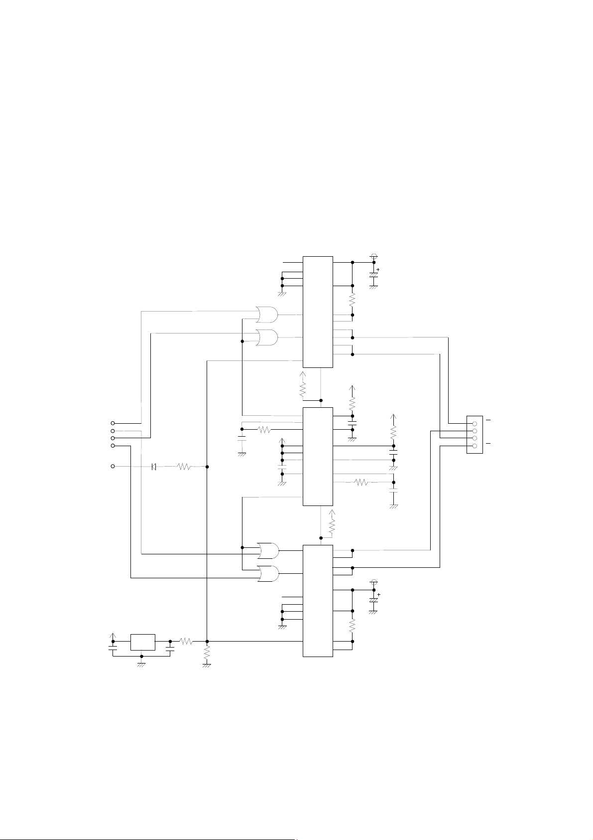
3.4.1 Motor Drive Circuit
4
1%
1%
3
11 20
16
20 11
6 1 15 14
12 12
3
19 6
Vp
18
2
12
(1) Sample Drive Circuit
Sample drive circuit for the motor are shown in Figure 3-3.
NC
9
1
13
14
LB1843V-E
10µF
0.51Ω
1%
1/2W
50V
15
5
3
74HC123A
9
LB1843V-E
19
7
6
10
Vcc
10KΩ
2
18
15
4
5
Vcc
3KΩ
1%
0.01µF
10%,10%
1KΩ
1%
0.51Ω
1%
1/2W
Vp
10µF
50V
Vcc
3KΩ
1%
0.01µF
10%,10%
0.01µF
10%,10%
6
A
7
B
8
A
9
B
PH1
PH2
PH3
PH4
CTCRL
0.1µF
Vcc
1SS294
(TE85L, F)
µPC1060C-A
1
74HC32
0.01µF
10%,10%
1.8KΩ
1%
2.7KΩ
2
0.1µF
3.3KΩ
1KΩ
1%
0.1µF
74HC32
NC
Vcc
10KΩ
Vcc
17
13
2
4
3
11
8
5
13
14
9
1
17
Figure 3-3 Sample Drive Circuit (Motor)
3-6
Page 21

(2) Excitation Sequence
L
H
H
B
As shown in Table 3-4, the LTP1245 feeds paper in the normal direction when the motor is excited
in the order of step 1, step 2, step 3, step 4, step 1, step 2, . . . . On the other hand, to rotate the
motor in a reverse direction, drive the motor in the reverse order of: step 4, step 3, step 2, step 1,
step 4, step 3, . . . .
Table 3-4 Excitation Sequence
Signal Name Sequence
Step 1 Step 2 Step 3 Step 4
A Low High High Low
B High High Low Low
A High Low Low High
B Low Low High High
A
B
H
L
H
A
L
L
1 DOT LINE
Figure 3-4 Input Voltage Signals for the Sample Drive Circuit (Motor)
3-7
Page 22

3.4.2 Motor Timing
H
H
PAUSE
STATE
Refer to the timing chart in Figures 3-5 and 3-6 when designing the control circuit or software for starting
and stopping the motor. Also take note of the following precautions:
Precautions for Designing the Motor Control Circuit and Software
(1) Stop step
To stop the motor, excite for a single step period with a phase that is the same as the last one in
the printing step.
(2) Pause state
In the pause state, do not excite the step motor in order to prevent the motor from heating. Even
when the step motor is not excited, it maintains a holding force to prevent paper from sliding.
(3) Start step
To restart the motor from the stop step, immediately shift the motor into the printing sequence.
To restart the motor from the pause (no excitation) state, shift the motor into the printing sequence
after outputting a phase that is the same as that of the stop step for a single step.
When using the Sample Drive Circuit (Motor) :
1 DOT LINE
PH1
L
H
PH2
L
H
PH3
L
PH4
L
STOP
STEP
START
STEP
PRINT STEP
PRINT STEP
Figure 3-5 Motor Start/Stop Timing (Sample Drive Circuit (Motor) )
3-8
Page 23

(4) Others
Do not print paper at the intermittent feed mode. Doing so may deteriorate the printing quality due
to irregular paper feeding pitch.
To print characters and bit images, always follow the start step and stop step.
3-9
Page 24
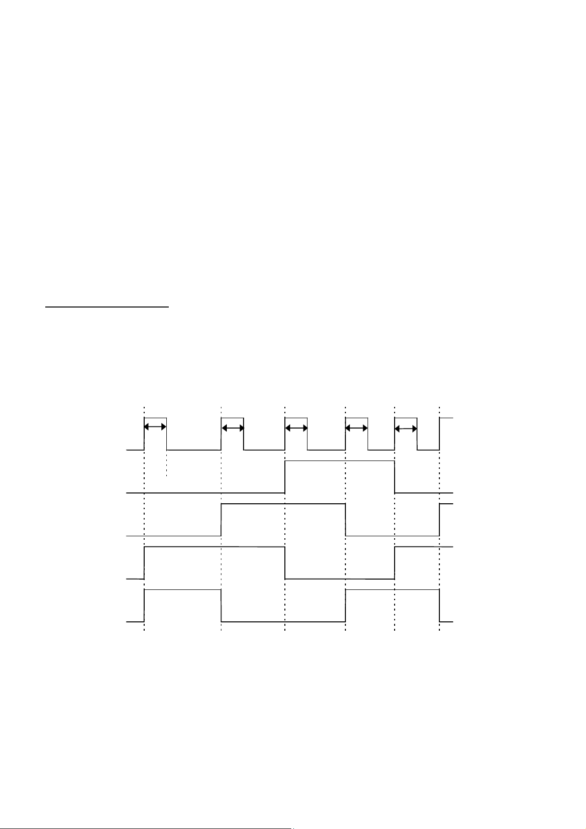
3.4.3 Precautions for Driving the Motor
CTCRL
PH1
PH2
PH3
PH4
(1) Motor Current Control
Low speed motor driving while printing due to a division drive method, print data, and input data transfer
speed may cause noise or print trouble to occur due to over torquing or overheating of the motor.
To prevent these from occurring, be sure to set the motor current as follows and perform two-current
control.
Activate the motor with the 1st setting current in each motor drive step.
Change the activation current to the 2nd setting current after activating the motor with the 1st setting
current for T1.
T1 is defined from each period of the motor drive step and Vp voltage as follows:
How to define T1 (unit: µµµµs)
When Vp is under 7.2 V :
T1: Compare the following two values and adopt the smaller one.
(Each period of the motor drive step - 500) and 925.9
When Vp is 7.2 V or more :
T1: Compare the following two values and adopt the smaller one.
(Each period of the motor drive step - 500) and (1000000 / (3600 - Vp × 350))
In use at temperature below -5°C, Control the 0.23(A) at 1st current.
T1 T1 T1 T1 T1
230mA
150mA
Start 1st step 2nd step 3rd step 4th step
(5.78ms)
Set the 1st setting current at CTCRL=“High”: 0.23 (A)
Set the 2nd setting current at CTCRL=“Low”: 0.15 (A)
(5.78ms) (3.57ms) (2.76ms) (2.31ms)
Figure 3-6 Motor Drive Timing Chart (in use at temperature over -5°°°°C)
3-10
Page 25
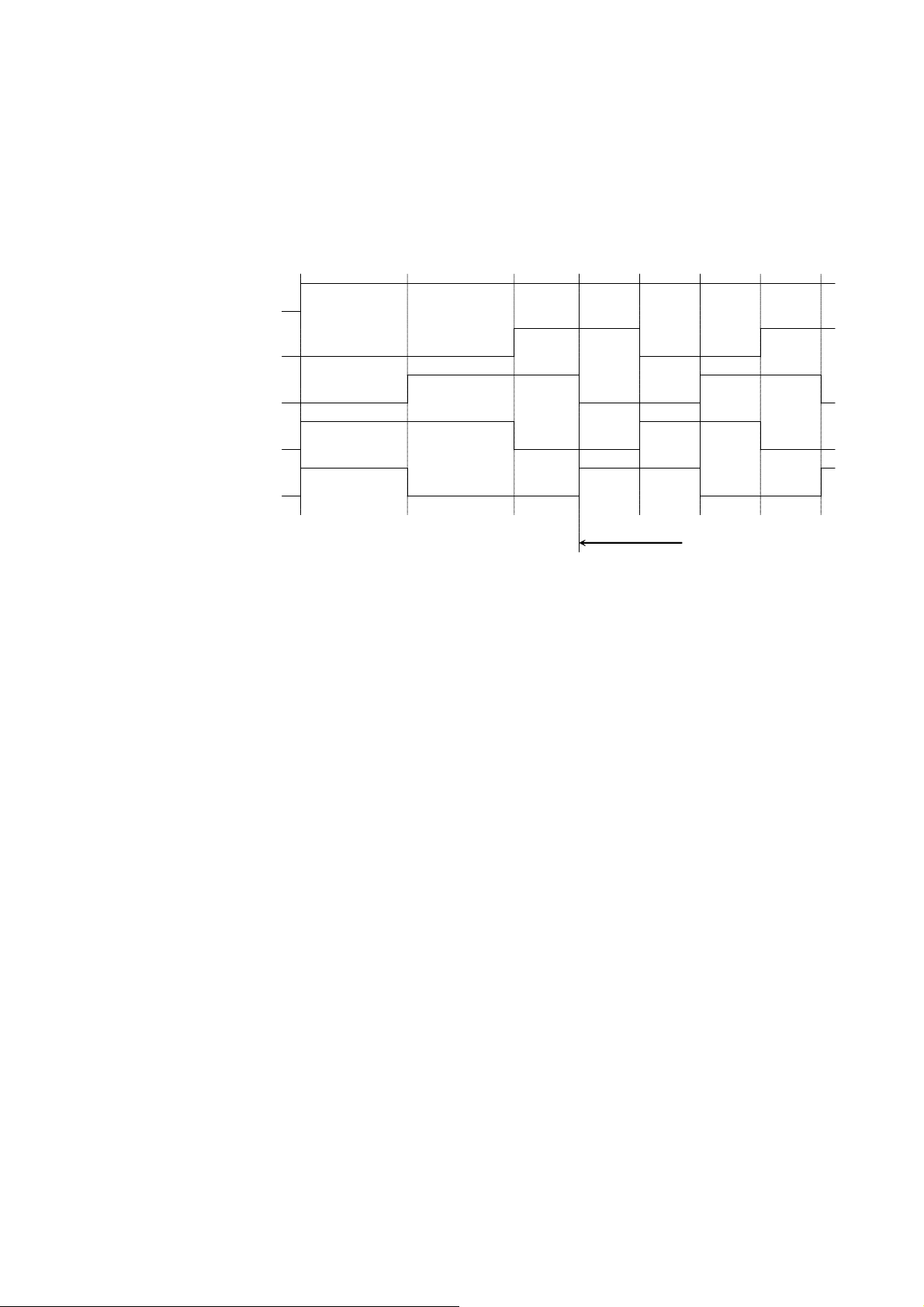
In use at temperature below -5°C
CTCRL1
230mA
PH1
PH2
PH3
PH4
Start
(5.78ms)
Motor speed = 300 pps CTCRL1=”High” First set current: 0.23 (A)
1st step
(5.78ms)
2nd step
(3.57ms)
Figure 3-7 Motor Drive Timing Chart (in use at temperature below -5°°°°C)
3rd step
(3.33ms)
4th step
(3.33ms)
Max speed=300pps
5th step
(3.33ms)
6th step
(3.33ms)
3-11
Page 26

(2) Acceleration Control
When driving the motor, acceleration control is needed to start paper feeding. When the motor is to be
driven at the motor drive frequency that is calculated using equation (1), the motor may come out of step
under heavy load.
Drive the motor to the maximum driving speed that is calculated using equation (1), according to the linear
acceleration table in Table 3-5.
The method for accelerating the motor is as follows:
1. Output start step (5780 (µs)).
2. Output first step for the first acceleration step time
3. Output second step for the second acceleration step time
4. Output n
th
step for the nth step acceleration time
5. After outputting the time calculated using equation (1), the motor is driven at a constant speed.
The printer can print during acceleration.
Set the maximum drive speed to 300 pps (3333 µs) for printing at lower than -5°C.
When accelerating it again after decreasing the speed, follow the method shown below.
When the step time is Tm (the reciprocal number of the frequency calculated using equation (1)),
compare Tm with the time that was taken in the previous step.
(1) In case Tm > time that was taken in the previous step (i.e. decreasing speed)
the closest acceleration step time to Tm and the acceleration step time that is larger thanTm, are
output.
(2) In case Tm < time that was taken in the previous step (i.e. reacceleration time)
the next closest acceleration step time to the previous step time or Tm, which is longer, is output.
3-12
Page 27
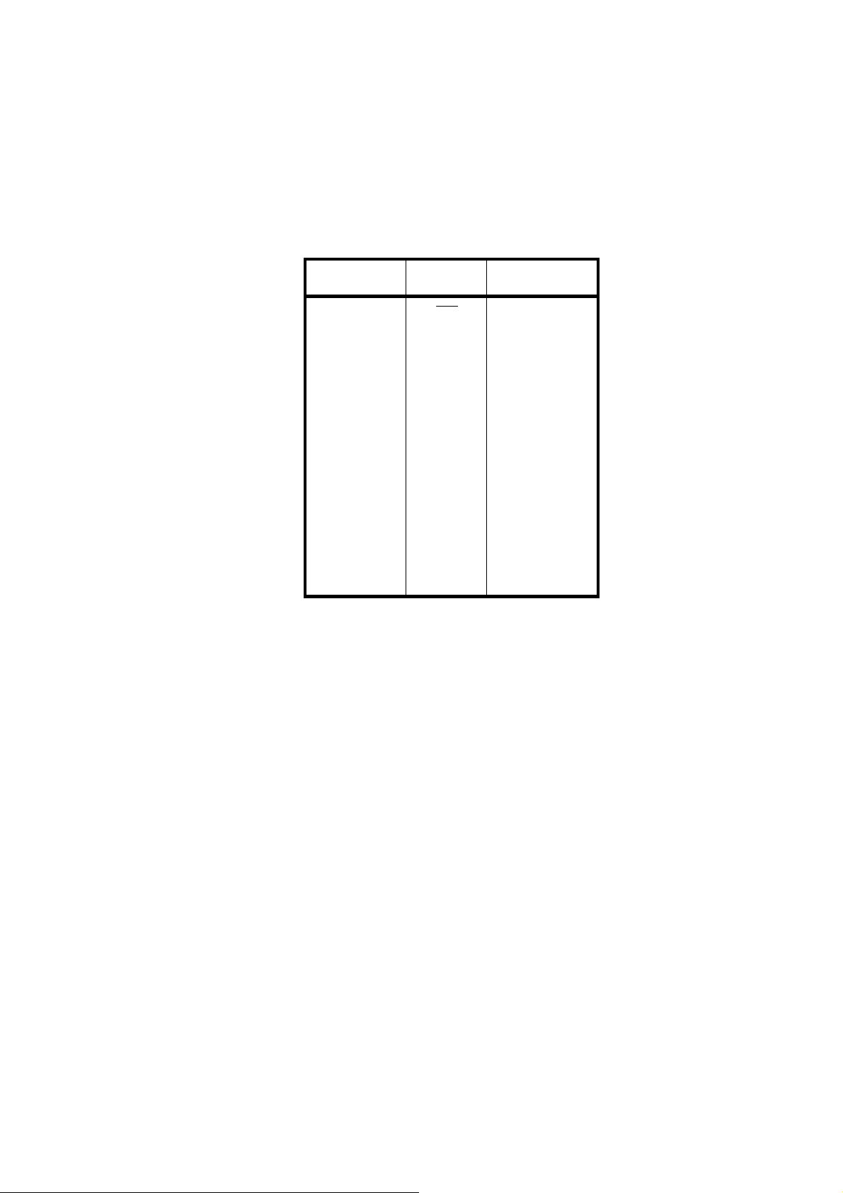
Table 3-5 Acceleration Steps
Number of
Steps
start
1
2
3
4
5
6
7
8
9
10
11
12
13
14
15
16
17
18
Speed
(pps)
173
280
362
432
493
547
597
644
687
728
768
805
840
874
907
939
970
1000
Step Time
(µs)
5780
5780
3571
2762
2314
2028
1828
1675
1553
1456
1374
1302
1242
1191
1144
1103
1065
1031
1000
3-13
Page 28

3.5 THERMAL HEAD
3.5.1 Structure of the Thermal Head
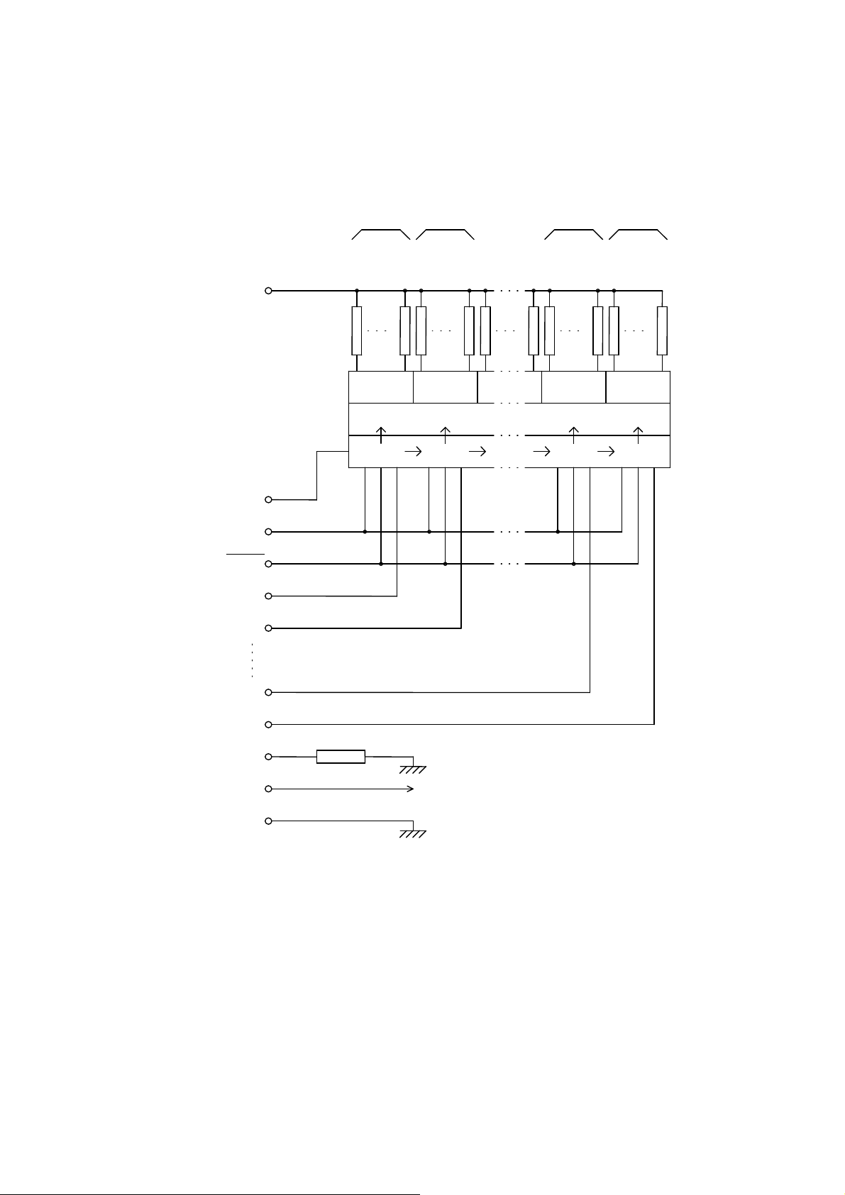
As Figure 3-8 shows, the LTP1245 thermal head consists of 384 heat elements, and heat element drivers.
Serial printing data input from the DAT terminal is transferred to the shift register synchronously with the
CLK signal, then stored in the latch register with the timing of the LATCH signal.
Inputting the head activation signal (DST 1 to 6) activates heat elements in accordance with the printing
data stored in the latch register.
A maximum of six division printing is available for the LTP1245.
Table 3-6 shows the relationship between DST signals and heat elements.
3-14
Page 29
Block6 Block5 Block2 Block1
Vp
DAT
CLK
LATCH
DST6
DST5
Heat Element
Output Driver
Latch Register
Shift Register
DOT 384
DOT 321
DOT 320
DOT 257
DOT 256
DOT 129
DOT 128
DOT 64
DOT 65
DOT 1
DST2
DST1
TH
Thermistor
Vdd
GND
Figure 3-8 Thermal Head Block Diagram
3-15
Page 30
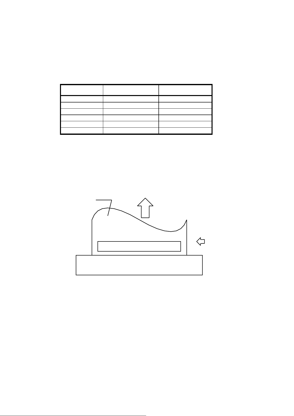
Table 3-6 Blocks and Activated Heat Elements
Block Number Heat Element Number Dots / Block
1 1 - 64 64
2 65 - 128 64
3 129 - 192 64
4 193 - 256 64
5 257 - 320 64
6 321 - 384 64
3.5.2 Printed Position of the Data
Data dots from 1 to 384 which are transferred through DAT are printed as shown in Figure 3-9.
PAPER
PAPER FEED DIRECTION
PRINT SURFACE
DATA PRINT SEQUENCE
1 2 3 4 5 6 ............................. 382 383 384
LTP1245 PRINTER MECHANISM
DATA INPUT SEQUENCE 1 2 3 4 5 6 . . . . . . 382 383 384
DATA IN
Figure 3-9 Printed Position of the Data
3-16
Page 31
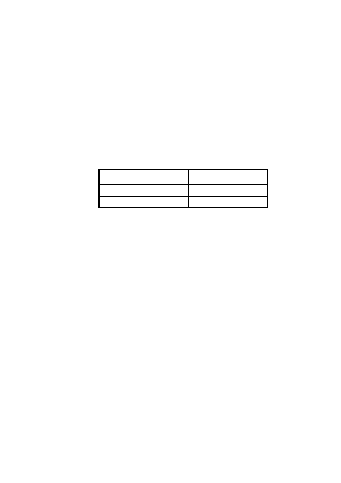
3.5.3 Head Resistance
N
× Vp
The LTP1245 head resistance is176 Ω ± 4 %.
3.5.4 Head Voltage
The LTP1245 has a built-in head driver IC and control IC. Table 3-7 shows the head voltage.
Table 3-7 Head Voltage
Item Voltage Range
Head drive voltage Vp
Head logic voltage Vdd
3.5.5 Peak Current
Since the peak current (maximum current) may reach the values calculated using equation (2) when the
thermal head is driven, make sure that the allowable current for the cable material and the voltage drop on
the cables are well within the specified range.
Equation (2):
Ip: Peak current (A)
N: Number of dots that are driven at the same time
Vp: Head drive voltage (V)
RH: Head resistance (Ω)
Ip=
RH
4.2 to 8.5 V
4.5 to 5.5 V
3-17
Page 32
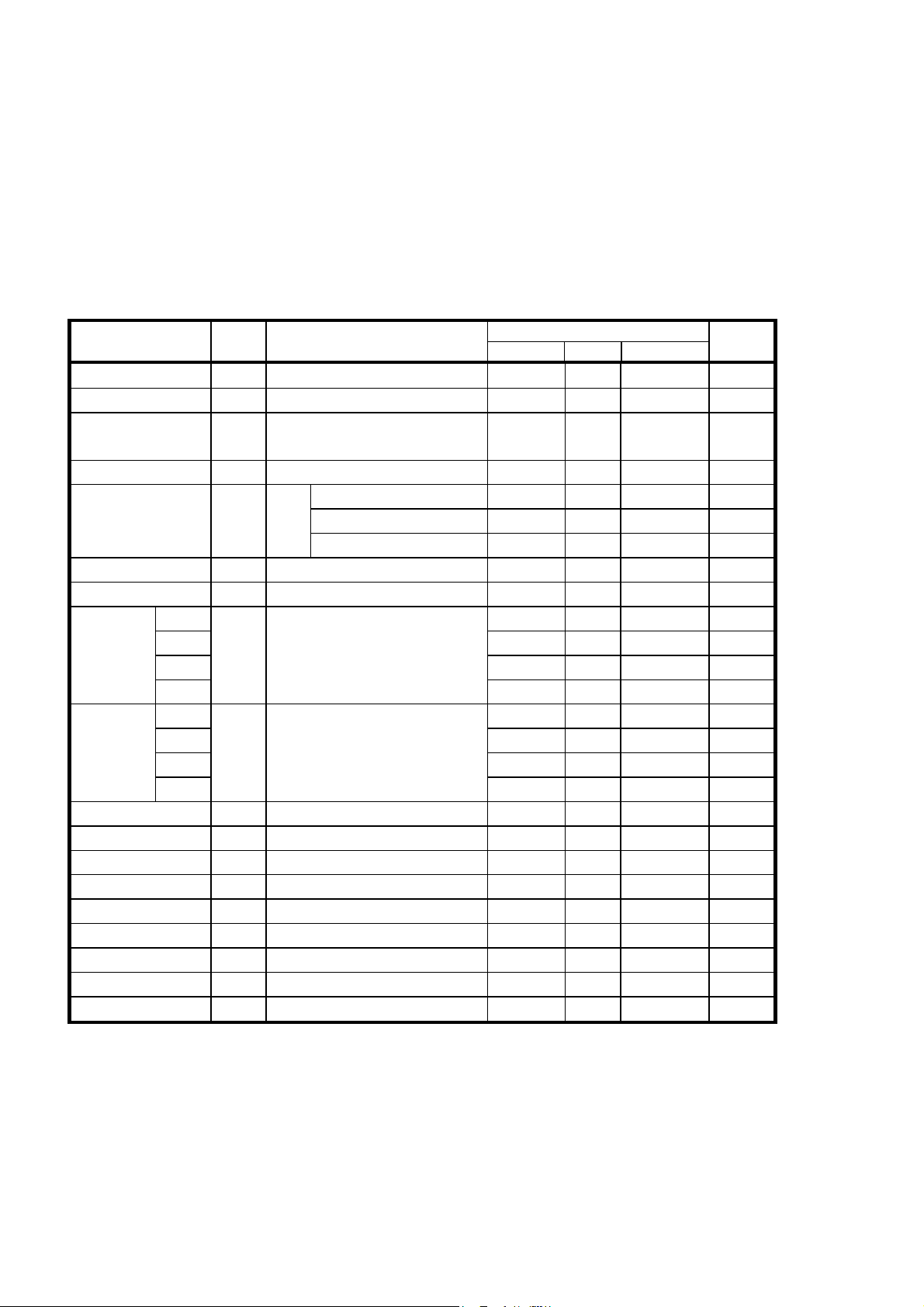
3.5.6 Thermal Head Electrical Characteristics
Table 3-8 Thermal Head Electrical Characteristics
(Vdd=4.5 to 5.5V, Ta=0 to 50°C)
Item Sinbol
Head resistance RH 169 176 183 Ω
Head drive voltage Vp 4.2 - 8.5 V
Head drive current
Logic block voltage Vdd 4.5 5.0 5.5 V
Logic block current Idd
"High" input voltage Vih CLK,DAT,LATCH,DST 0.8×Vdd
"Low "input voltage Vil CLK,DAT,LATCH,DST 0 - 0.2×Vdd V
"High"input
current
"Low "input
current
Driver leak current Ileak Vp=7(V), for 1 bit - - 1.0 µA
CLK frequency fclk - - 4 MHz
CLK pulse width t1 See the Timing Chart 80 - - ns
DAT setup-time t2 See the Timing Chart 50 - - ns
DAT hold time t3 See the Timing Chart 50 - - ns
LATCH setup time
LATCH pulse width t5 See the Timing Chart 120 - - ns
LATCH hold time t6 See the Timing Chart 120 - - ns
DST setup time t7 See the Timing Chart 120 - - ns
CLK
DAT
LATCH
DST
CLK
DAT
LATCH
DST
Ip Vp=8.5 V, max. simultaneously
activated dot “64”
Ta=
25°C
Ta=25°C
Iih
Vdd=5.0(V)
Vih=5.0(V)
Ta=25°C
Iil
Vdd=5.0(V)
Vil=0(V)
t4 See the Timing Chart 120 - - ns
Conditions
Waiting for activation - - 0.5 mA
fclk=4MHz,DAT=fixed - - 6 mA
fclk=4MHz,DAT=1/2fclk
MIN TYP
2.5 2.6 2.7 A
- - 10 mA
- - 3 µA
- - 0.5 µA
- - 3 µA
- - 55 µA
- - -3 µA
- - -0.5 µA
- - -3 µA
- - -0.5 µA
Rated
MAX
- Vdd V
Unit
3-18
Page 33
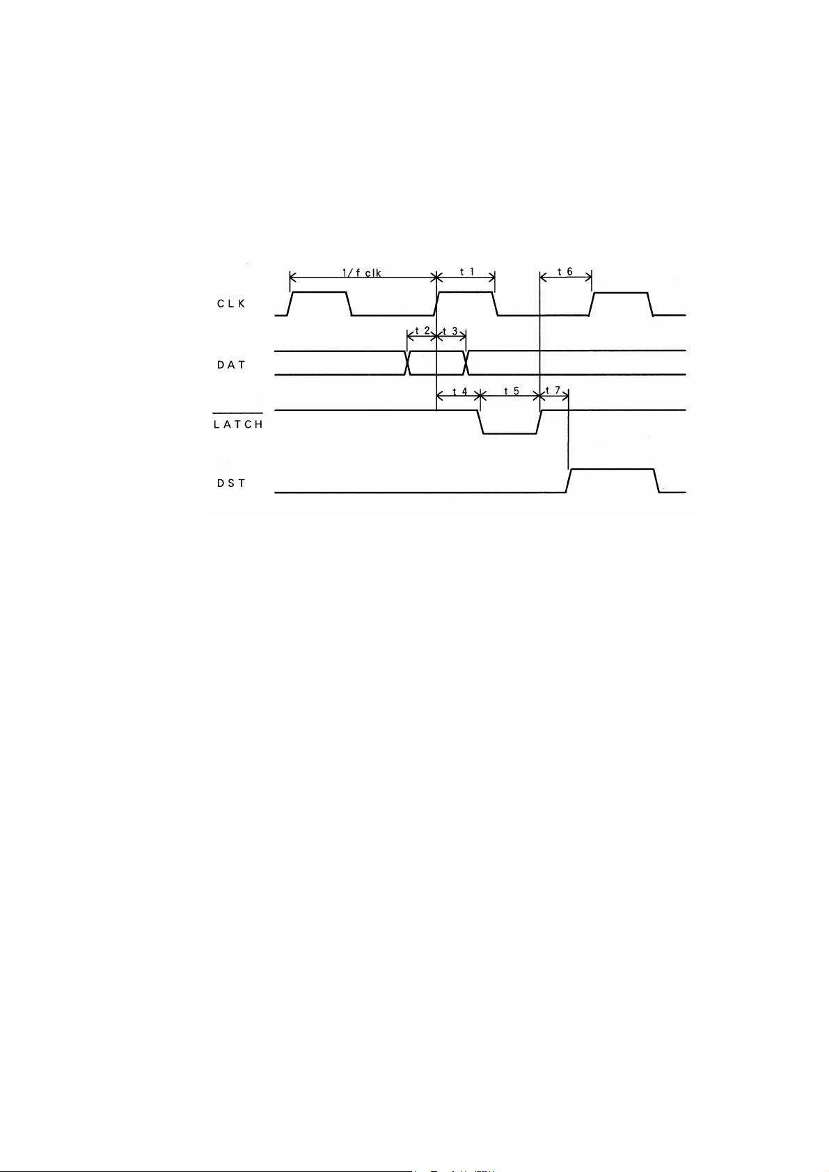
3.5.7 Timing Chart
Figure 3-10 Timing Chart
3-19
Page 34

3.6 CONTROLLING THE HEAD ACTIVATION (DST) PULSE WIDTH
3.6.1 Calculation of Head Activation Pulse Width
Head activation pulse width is calculated using the following equation (3).
To execute high quality printing using the LTP1245, the value that is calculated using the following
equation (3) must be adjusted according to the printer’s installation environment. Calculate each value
used according to the steps in Sections 3.6.2 to 3.6.6 and apply the pulse width with the t value that is
obtained by substituting each value into the equation (3).
Printing using too high voltage or too long pulse width may shorten the life of the thermal head.
Equation (3):
E × R
t = × C
V2
t : Head pulse width (ms)
E : Standard applied energy (mJ) See Section 3.6.2.
V : Applied voltage (V) See Section 3.6.3.
R : Head resistance (Ω) See Section 3.6.4.
C : Head pulse term coefficient See Section 3.6.6.
3.6.2 Calculation of Applied Energy
Applied energy should be in accordance with the temperature of the thermal head and the printer’s
installation environment
The thermal head has a built-in thermistor. Measure the temperature using thermistor resistance.
Standard applied energy is based on using the recommended thermal paper (59 µm) and a temperature of
25°C. Calculate the printing energy using equation (4) and the paper coefficient and temperature
coefficient.
Equation (4):
E= (0.285 - T
× (TX - 25) ) × P
C
T
: Detected temperature using the thermistor (°C) 1
X
P : Thermal paper coefficient
Normal thermal paper 1.0
TL69KS-HG76 (label paper) 1.35
TL69KS-R2 (90µm paper) 1.5
T
TL51KS-R2 (62µm paper) 1.5
TW80KK-S (2-ply paper) 2.4
: Temperature coefficient
C
2
TL69KS-R2 0.00285
TL51KS-R2 0.00285
TW80KK-S 0.0037
Other thermal papers 0.003135
1
The thermistor resistance value at TX (°C). See
2
For driving for 2-ply thermal paper, see
Section 3.6.8
Section 3.6.9
.
.
3-20
Page 35

3.6.3 Adjustment of Head Activation Voltage
Adjustment of head activation pulse width due to changing the head activation voltage is to be in
accordance with equation (5). The adjustment method differs if the head drive voltage (Vp) is 5.5 V or
more or under 5.5 V.
If head temperature is above -5°C
Equation (5):
(5.5 V or more)
V=Vp × 1.2 - 1.8
(under 5.5 V)
V=Vp × 1.4 - 2.9
Vp: Head activation voltage (V)
If head temperature is below -5°C
More than 5.5V : V = Vp ×1.2 - 1.8 + T × 0.01
Less than 5.5V : V = Vp ×1.4 - 2.9 + T × 0.01
T: Thermistor detection temperature (°C)
3.6.4 Adjustment of Head Resistance
Adjustment of head resistance is to be in accordance with equation (6). Due to wiring resistance there is a
drop in voltage.
Equation (6):
( RH + 25 + (RC + rC ) × N ) 2
R=
RH
RH: Head resistance 178.5 (Ω)
25: Wiring resistance in the thermal head (Ω)
R
r
: Common terminal wiring resistance in the thermal head: 0.1 (Ω)
C
: Wiring resistance between VP and GND (Ω) 1
C
N: Number of dots driven at the same time
1
This resistance is the resistance of the wire used between the FFC terminal of thermal head, the power supply,
the resistance of switching circuit of relay, etc.
3-21
Page 36

3.6.5 Determination of Activation Pause Time and Activation Pulse Period
Dot lines may be activated in succession to the same thermal dot in order to protect thermal head
elements. Determine the activation period (the time from the preceding activation start to the current
activation start) which conforms to equation (7) to reserve the pause time.
Equation (7):
W > t + 0.5(ms)
W : Activation period of 1-dot line (ms)
3.6.6 Head Activation Pulse Term Coefficient
Make adjustments using the head activation pulse term coefficient (motor drive frequency or equivalent)
as the printing density changes by the printing speed.
According to equations (8), calculate compensation coefficient C of the heat pulse.
Equation (8):
C = 1 -1.15/(1.9+W)
W = 2000 / motor drive frequency
3-22
Page 37
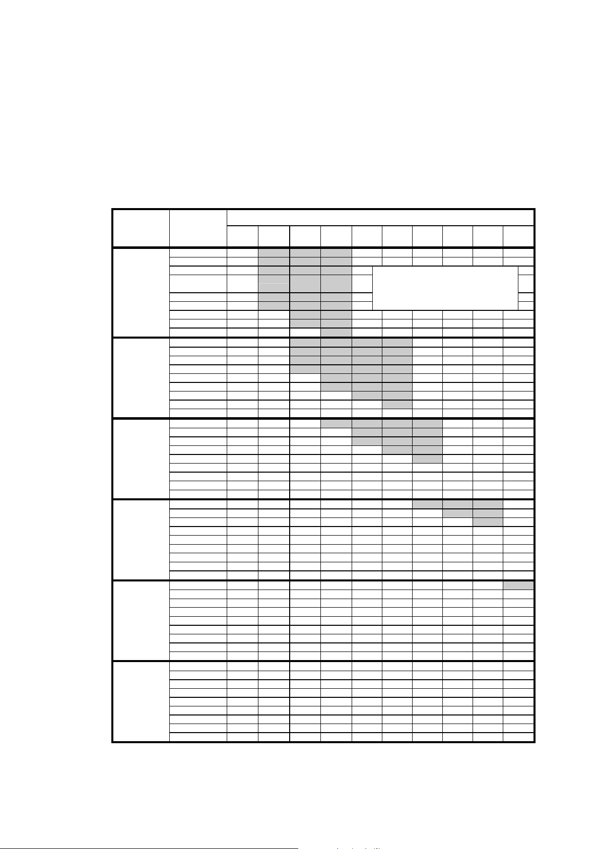
3.6.7 Calculation Sample for the Head Activation Pulse Width
Table 3-9 displays the calculation sample of the head activation pulse width that was calculated using
equation (3) and the values obtained using equations (4) to (8).
Table 3-9 Activation Pulse Width
Head Drive
Voltage (V)
0 9.92
10 9.07
20 8.21
30 7.35
4.2 40 6.50
50 5.64
60 4.79 4.56
70 3.93 3.75
80 3.07 2.93 2.81
0 5.24 5.00
10 4.79 4.57
20 4.34 4.14
30 3.89 3.70
5.0 40 3.43 3.27 3.14
50 2.98 2.84 2.72
60 2.53 2.41 2.31 2.22
70 2.08 1.98 1.90 1.83 1.76
80 1.62 1.55 1.48 1.43 1.38 1.34
0 3.02 2.88 2.76
10 2.76 2.63 2.52 2.43
20 2.50 2.38 2.28 2.20
30 2.24 2.14 2.05 1.97 1.90
6.0 40 1.98 1.89 1.81 1.74 1.68 1.63
50 1.72 1.64 1.57 1.51 1.46 1.42 1.38
60 1.46 1.39 1.33 1.28 1.24 1.20 1.17
70 1.20 1.14 1.09 1.05 1.02 0.99 0.96
80 0.94 0.89 0.86 0.82 0.80 0.77 0.75
0 1.88 1.80 1.72 1.66 1.60 1.55
10 1.72 1.64 1.57 1.51 1.46 1.42 1.38
20 1.56 1.49 1.42 1.37 1.32 1.28 1.25 1.21
30 1.40 1.33 1.28 1.23 1.19 1.15 1.12 1.09 1.06
7.2 40 1.23 1.18 1.13 1.08 1.05 1.02 0.99 0.96 0.94
50 1.07 1.02 0.98 0.94 0.91 0.88 0.86 0.83 0.81
60 0.91 0.87 0.83 0.80 0.77 0.75 0.73 0.71 0.69
70 0.75 0.71 0.68 0.66 0.63 0.61 0.60 0.58 0.57
80 0.58 0.56 0.53 0.51 0.50 0.48 0.47 0.45 0.44
0 1.45 1.38 1.32 1.27 1.23 1.19 1.16 1.13 1.10
10 1.32 1.26 1.21 1.16 1.12 1.09 1.06 1.03 1.01 0.98
20 1.20 1.14 1.10 1.05 1.02 0.99 0.96 0.93 0.91 0.89
30 1.07 1.02 0.98 0.94 0.91 0.88 0.86 0.84 0.82 0.80
8.0 40 0.95 0.90 0.87 0.83 0.81 0.78 0.76 0.74 0.72 0.71
50 0.82 0.79 0.75 0.72 0.70 0.68 0.66 0.64 0.63 0.61
60 0.70 0.67 0.64 0.61 0.59 0.58 0.56 0.54 0.53 0.52
70 0.57 0.55 0.52 0.50 0.49 0.47 0.46 0.45 0.44 0.43
80 0.45 0.43 0.41 0.39 0.38 0.37 0.36 0.35 0.34 0.33
0 1.25 1.19 1.14 1.10 1.06 1.03 1.00 0.97 0.95 0.93
10 1.14 1.09 1.04 1.00 0.97 0.94 0.91 0.89 0.87 0.85
20 1.03 0.99 0.94 0.91 0.88 0.85 0.83 0.81 0.79 0.77
30 0.93 0.88 0.85 0.81 0.79 0.76 0.74 0.72 0.70 0.69
8.5 40 0.82 0.78 0.75 0.72 0.69 0.67 0.65 0.64 0.62 0.61
50 0.71 0.68 0.65 0.62 0.60 0.58 0.57 0.55 0.54 0.53
60 0.60 0.57 0.55 0.53 0.51 0.50 0.48 0.47 0.46 0.45
70 0.49 0.47 0.45 0.44 0.42 0.41 0.40 0.39 0.38 0.37
Note) The above table shows values for the 59 µm recommended thermal paper (TF50KS-E2D), Rc+rc=0.16 Ω, and N=64.
In the shaded area, the drive pulse width exceeds the allowable activation pulse width or the activation pulse width
80 0.39 0.37 0.35 0.34 0.33 0.32 0.31 0.30 0.29 0.29
exceeds the motor drive frequency. Therefore, use the motor drive frequency shown in the unshaded area.
Thermistor
Temperature
℃
Motor Drive Frequency (PPS)
100 200 300 400 500 600 700 800 900 1000
Do not use this area because paper
feed errors may occur because of the
motor torque.
3-23
Page 38
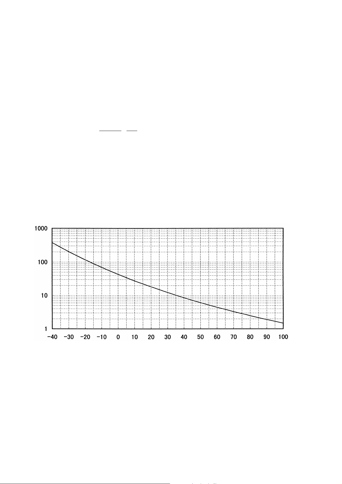
3.6.8 Thermistor Resistance
Ω
Ω
°°°°
=
The resistance of the thermistor at the operating temperature T
(°C) is determined using the following
X
equation (10).
Equation (10):
X
25
BEXPR-R
1
××
−
X
+
T273
1
298
R
R
: Resistance at operating temperature Tx (°C)
X
: 15 kΩ ± 10% (25°C)
25
B: 3440 K ± 3%
T
: Operating temperature (°C)
X
EXP (A): The Ath power of natural logarithm e (2.71828)
[Rating]
Operating temperature range: -40°C to +125°C
)
RESISTANCE (k
TEMPERATURE (
C)
Figure 3-11 Thermistor Resistance vs. Temperature
R
E
S
I
S
T
A
N
C
E
(KΩΩΩΩ)
3-24
Page 39
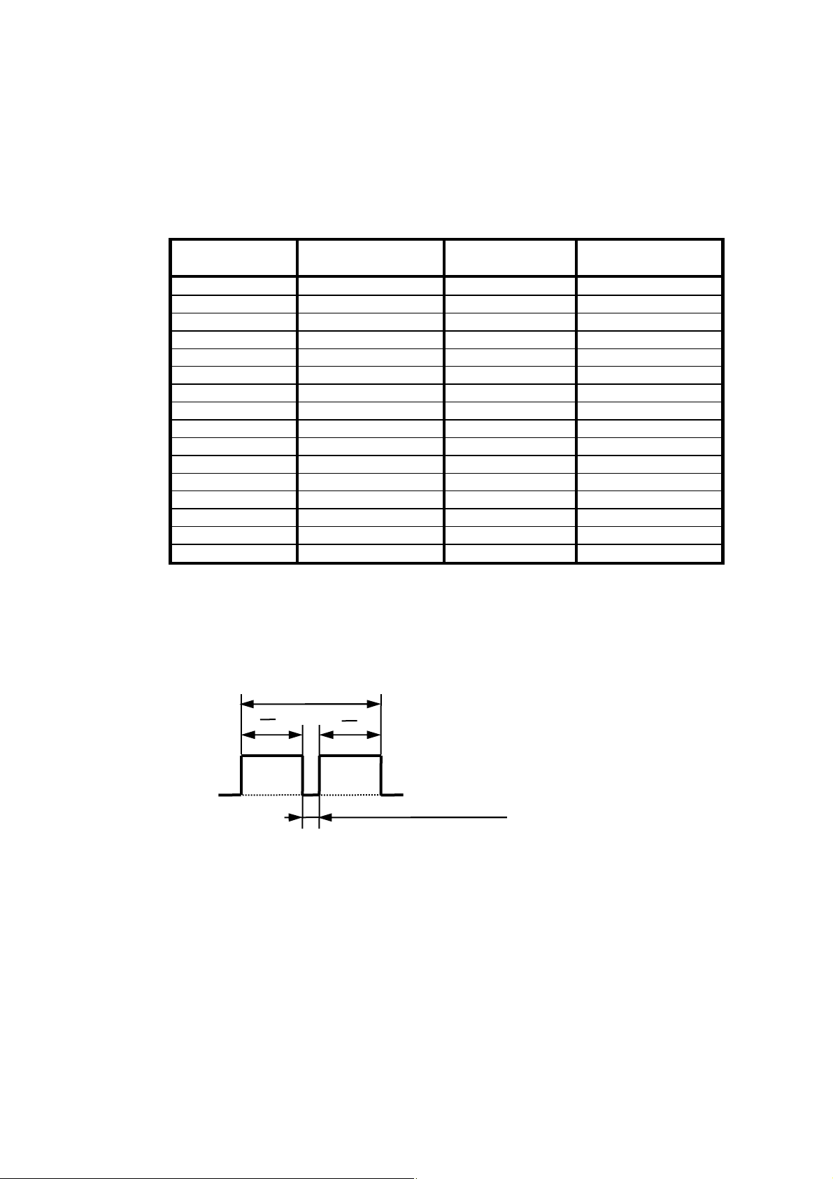
Table 3- 10 Temperature and Corresponding Thermistor Resistance
Temperature
(°°°°C)
-40 375.54 40 8.63
-35 275.39 45 7.26
-30 204.55 50 6.14
-25 153.76 55 5.22
-20 116.89 60 4.46
-15 89.82 65 3.83
-10 69.71 70 3.30
-5 54.61 75 2.86
0 43.17 80 2.48
5 34.42 85 2.17
10 27.66 90 1.90
15 22.40 95 1.67
20 18.27 100 1.47
25 15.00
30 12.40
35 10.31
3.6.9 How to Print Using 2-ply Thermal Paper
For fine printing, drive the thermal elements two times at half of the drive pulse that was calculated using
equation (3) in Section 3.6.1.
t
2
Thermistor
Resistance (kΩΩΩΩ)
PRINTING TIME
300µµµµs (INTERVAL TIME)
t
2
Temperature
(°°°°C)
t : HEAD DRIVE PULSE WIDTH (ms)
Figure 3-12 How to Drive 2-ply Thermal Paper
Thermistor
Resistance (kΩΩΩΩ)
3-25
Page 40

3.6.10 Detecting Abnormal Temperatures of the Thermal Head
To protect the thermal head and to ensure personal safety, abnormal thermal head temperatures must be
detected by both hardware and software as follows:
Detecting abnormal temperatures by software
Design software that will deactivate the heat elements if the thermal head thermistor (TH) detects
a temperature higher than 80 °C (thermistor resistance RTH ≤ 2.48 kΩ), and reactivate the heat
elements when a temperature lower than 60 °C (RTH ≥ 4.46 kΩ) is detected. If the thermal head
continues to be activated at a temperature higher than 80 °C, the life of the thermal head may be
shortened significantly.
Detecting abnormal temperatures by hardware
If the control unit (CPU) malfunctions, the software for detecting abnormal temperatures may not
function properly, resulting in overheating of the thermal head. Overheating of the thermal head
may cause damage to the thermal head or cause skin burns.
Always use hardware in conjunction with software for detecting abnormal temperatures to ensure
personal safety. (If the control unit malfunctions, it may be impossible to prevent damage to the
thermal head even if a detection of abnormal temperature is detected by hardware.).
Using a window comparator circuit or similar detector, design hardware that detects the following
abnormal conditions:
(a) Overheating of the thermal head (approximately 100 °C or higher (RTH ≤ 1.47 kΩ)).
(b) Faulty thermistor connection (the thermistor may be open or short-circuited).
If (a) and (b) are detected, immediately deactivate the heat elements. Reactivate the heat
elements after they have returned to normal.
3-26
Page 41
3.7 HEAD-UP/PAPER DETECTOR
LTP1245 has a built-in head-up detector to detect whether the head is up or down and a paper detector to
detect whether paper is present or exhausted.
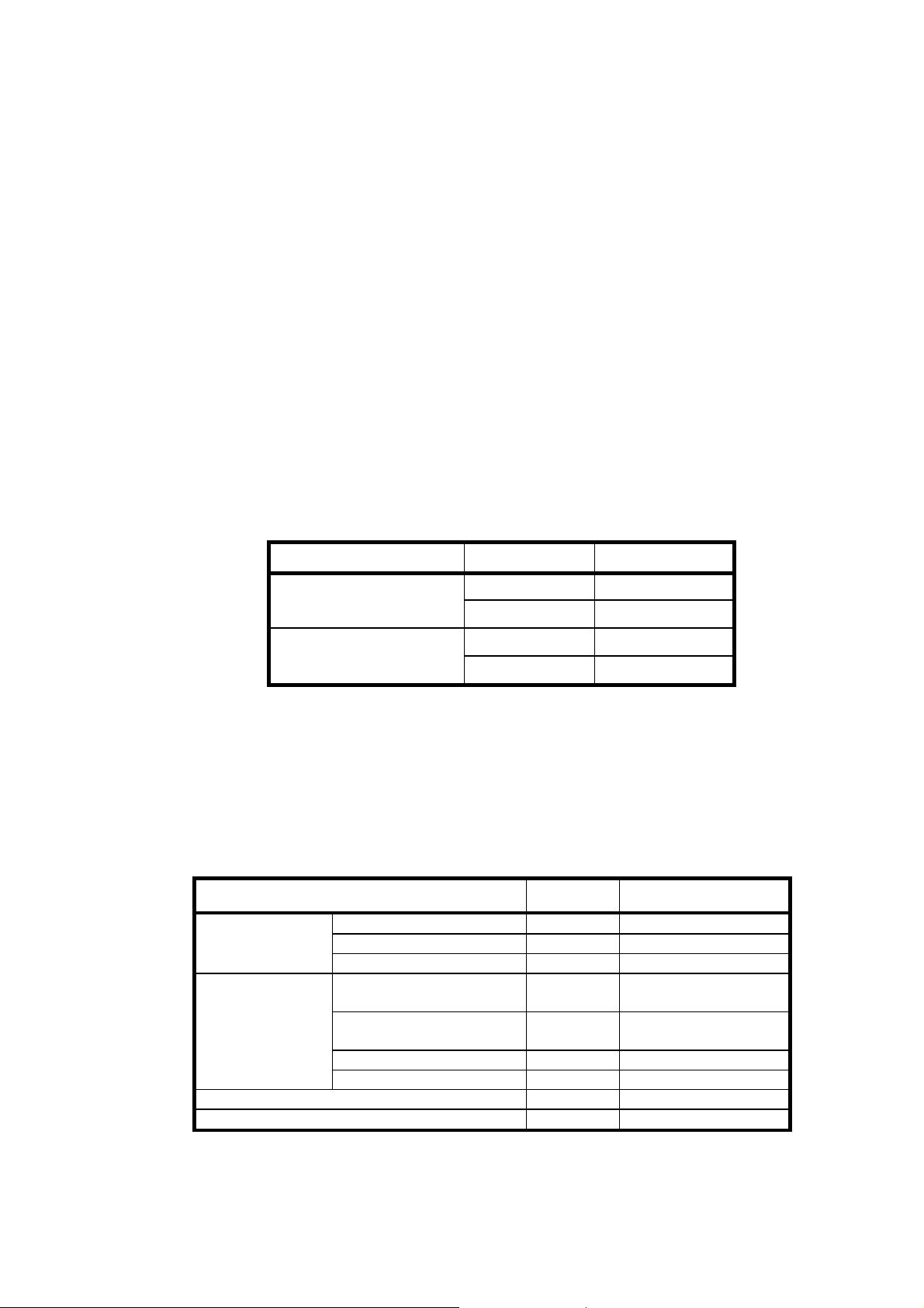
Both detectors are reflection photo interruptors which are designed to output signals as shown in Table
3-11 according to their status.
The external circuit should be designed so that it detects output from the head-up and paper detector and
does not activate the thermal head when the head is in the up position and paper is exhausted. If the
thermal head is activated in the head up position, the thermal head may be damaged or the life of the head
may be shortened significantly. If the thermal head is activated in an out-of paper mode, the thermal head
and platen roller may be damaged.
Table 3-11 Detector’s Status and Output Signals
Detector Status Output signal
Head up detector
Paper detector
* Sensing by the head up detector is delayed from the actual completion of the
head up/down action.
3.7.1 General Specifications
Table 3-12 Absolute Maximum Ratings of Detectors
Item Symbol Rating
LED (input)
Phototransistor
(output)
Operating temperature T
Storage temperature T
Forward current I
Peak forward current I
Reverse voltage V
Collector-to-emitter
voltage
Emitter-to-collector
voltage
Collector current I
Collector loss P
Head down “Low”
Head up “High”
Paper exist “Low”
No paper “High”
F
FM
R
V
CEO
V
ECO
C
C
opr
stg
-25°C to + 85°C
-40°C to + 100°C
(at 25°C)
30 mA
0.4 A
5 V
30 V
5 V
20 mA
50 mW
3-27
Page 42
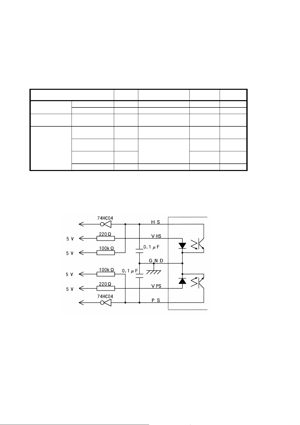
Table 3-13 Detectors Input / Output Conditions
Item Symbol
Forward voltage
(input)
Photo-transistor
Reverse current
Dark current I
(output)
Transfer
characteristics
Photo electric
current
Response time
(at rise)
Response time
(at fall)
1
d = sensing distance
Leak current I
3.7.2 Sample External Circuit
Conditions Std. Max.
V
I
CEO
I
IF=10mA 1.15V 1.3V LED
F
VR=5V - 10µA
R
VCE=24V - 0.1µA
IF=10mA, VCE=5V 450µA 1100µA
C
tr IC=1mA, VCE=10V 10µs -
tf RL=1kΩ, d=1mm 1 10µs -
LEAK IF
=10mA, VCE=5V - 0.2µA
The HS signal is high when the thermal head is in the “up” position.
The PS signal is high when paper is exhausted.
Figure 3-13 Sample External Circuit of the Head-Up/Paper Detector
3-28
Page 43
3.7.3 Automatic Paper Load
*
specified number of steps.
Stand
-
by for print operation
*
Deviation in the force of the rubber roller
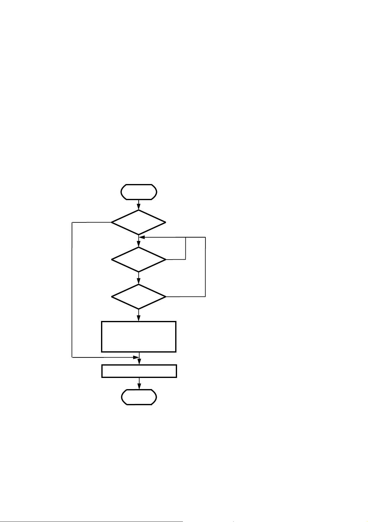
Paper can be automatically loaded when used in conjunction with the paper detector. To prevent paper
from skewing, cut the edges at right angles in line with the paper feed direction before loading it.
If skewed, feed the paper until it is straight, or place the head in the up position and adjust the paper so that
it is fed straight.
Figure 3-13 shows a flowchart for automatically loading paper.
START
Paper exists.
Paper is
exhausted.
Paper is present.
CHECK FOR
PAPER
CHECK FOR
PAPER
Head up/down
detection
Head down
Drive the motor in the
normal direction by the
END
Paper is
exhausted.
Head up
Drive the motor at lower than the frequency
during automatic paper loading described in
3.3 PAPER FEED CHARACTERISTICS.
Set the number of motor drive steps in
consideration of:
•
to catch the paper
• Distance to the paper eject
The distance between the paper detector and
the heat elements is approximately 8 mm.
Figure 3-14 Flowchart for Automatic Paper Load
3-29
Page 44
3.8 Mode Code Label
123456789
XYZ
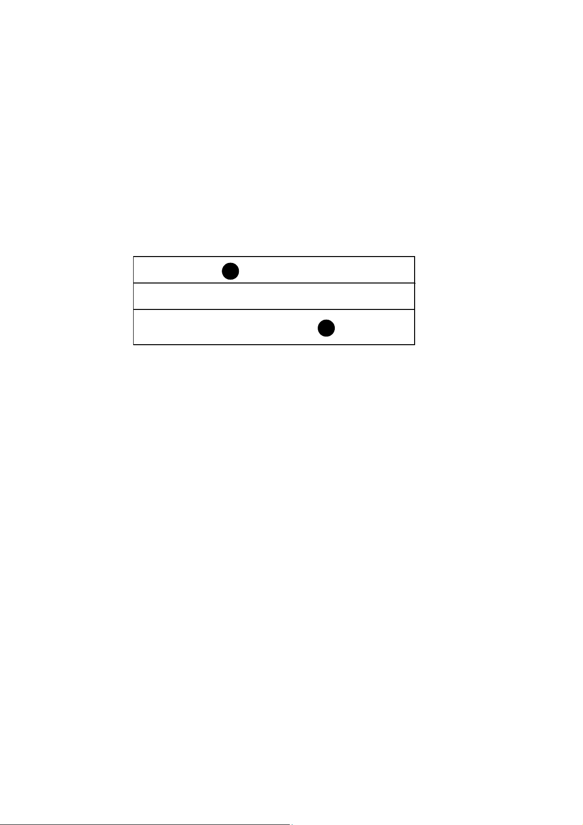
Figure 3-14 shows that the printer is the LTP1245R-C384-E which is made in September 2004.
See Figure 7-1 LTP1245R-C384-E Appearance and Dimensions for labeling position.
(1) Manufactured year: 2004
(2) Model code: LTP1245R-C384-E
(3) Manufactured month: September (X: October, Y: November, Z: December)
3 4 5 6 7 8 9 0
2
1
LTP1245R-C384-E
Figure 3-15 Model Code Label
3-30
Page 45

CHAPTER
CONNECTING EXTERNAL CIRCUITS
The LTP1245 has two types of connectors to connect it to the external circuits: FPC (Flexible Printed
Cable) type connector and FFC (Flexible Flat Cable) type connector.
Table 4-1 shows the recommended connectors.
Table 4-1 Recommended Connectors
No. External Circuit
Functions
Thermal head control
1
Motor control, paper
2
detection, and head-up
detection
Number of
Pins
20
9
4
Recommended Connectors
(External Circuit side)
Molex Co., Ltd.
52044-2045 (horizontal type)
52045-2045 (vertical type)
5597-20APB7F (horizontal type)
5597-20CPB7F (vertical type)
Molex Co., Ltd.
52030-0919 (vertical type)
52089-0929 (horizontal type)
4-1
Page 46
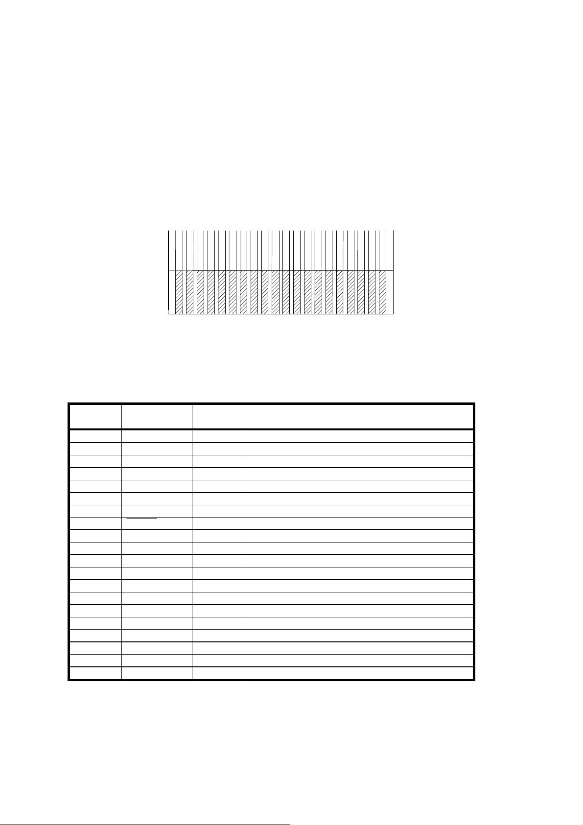
4.1 THERMAL HEAD CONTROL TERMINALS
Figure 4-1 shows the FFC terminals of the thermal head control.
20
1
Figure 4-1 Thermal Head Control Terminals (FFC)
Table 4-2 Thermal Head Control Terminal Assignments
Terminal
Number
1 Vp
2 Vp
Signal Name Input/
Output
Input Thermal head drive voltage
Input Thermal head drive voltage
Function
3 GND - GND
4 GND - GND
5 GND - GND
6 DAT Input Print data input (serial input)
7 CLK Input Synchronizing signal for data transfer
8 LATCH Input Print data latch (memory storage)
9 DST6 Input Thermal head print activation instruction signal
10 DST5 Input Thermal head print activation instruction signal
11 DST4 Input Thermal head print activation instruction signal
12 DST3 Input Thermal head print activation instruction signal
13 DST2 Input Thermal head print activation instruction signal
14 DST1 Input Thermal head print activation instruction signal
15 TH - Thermistor
16 Vdd Input Logic power supply (5V)
17 GND - GND
18 GND - GND
19 Vp
20 Vp
Input Thermal head drive voltage
Input Thermal head drive voltage
4-2
Page 47
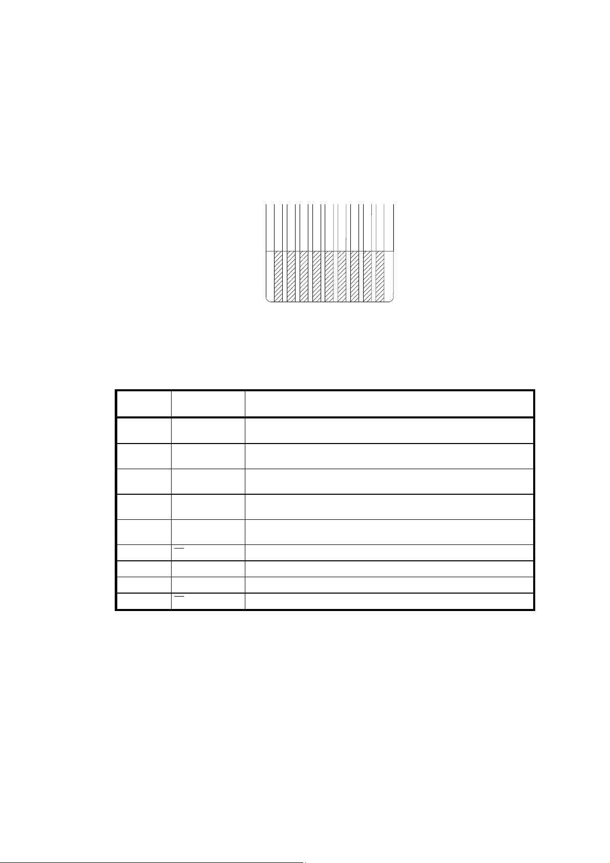
4.2 MOTOR AND DETECTOR TERMINALS
Figure 4-2 shows the FPC terminals of the motor control, paper detector and head-up detector.
9
1
Figure 4-2 Motor and Detector Terminals (FPC)
Table 4-3 Motor and Detector Terminals Assignments
Terminal
Signal Name
Function
Number
1 HS
Output signal of the head-up detector
(collector output of a photo-transistor)
2 V
HS
Power supply of the head-up detector
(LED anode)
3 GND GND
(common ground for the head-up and paper detectors)
4 PS Output signal of the paper detector
(collector output of a photo-transistor)
5 VPS Power supply of the paper detector
(LED anode)
6
7
8
9 B Motor drive signal
A Motor drive signal
B Motor drive signal
A Motor drive signal
4-3
Page 48

4-4
Page 49
CHAPTER
5
DRIVE METHOD
5.1 THERMAL HEAD DRIVE TIMING
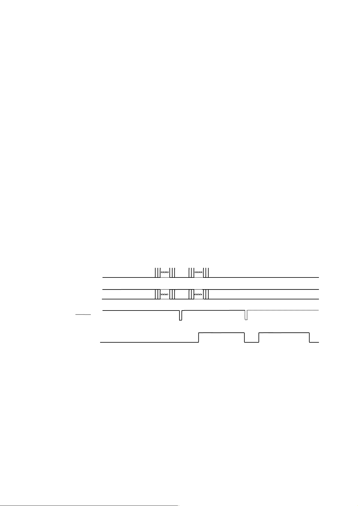
Input of print data
Input of DAT and CLK transfer the print data to the shift register in serial input. “High” means
printing and “Low” means no-printing in DAT. DAT data is read in at the rising edge of the CLK
inputs. The transferred line of data is stored in the latch register by turning LATCH to “Low”.
Input of the head activation pulse
"High" of DST drives the heat elements of the thermal head. Then let DST go to "Low" after driving
for the period calculated using the formula shown in "3.6 CONTROLLING THE HEAD
ACTIVATION (DST) PULSE WIDTH".
Figure 5-1 shows the example of timing chart of the thermal head driving.
CLK
DAT
Data transfer
Data transfer
1
LATCH
Latching data
DST
1:
The print data for next dot line can be transfered immediately after storing the print data into the latch register.
Figure 5-1 Example of Timing Chart of the Thermal Head Driving
5-1
Page 50

5.2 MOTOR DRIVE TIMING
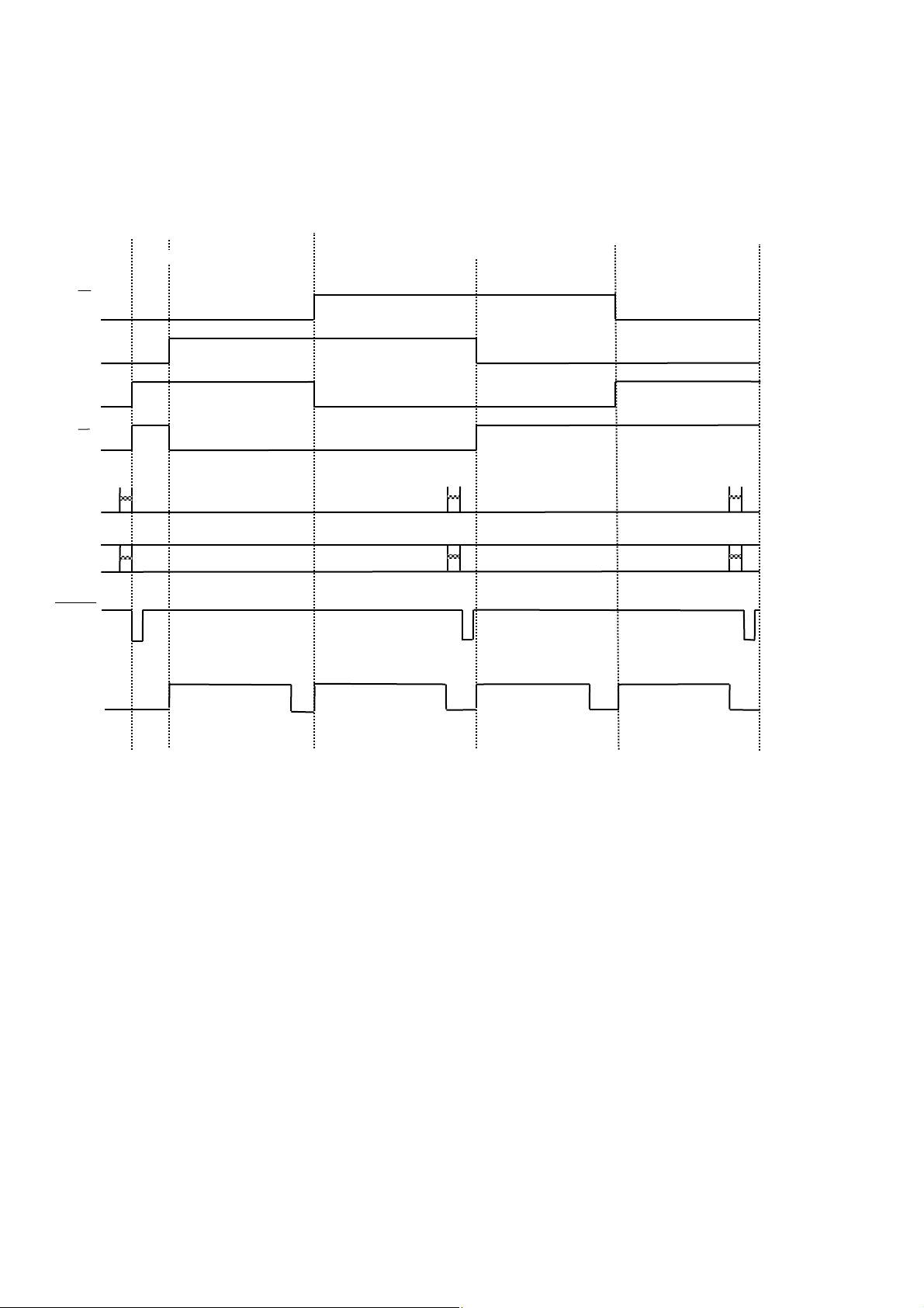
The phase of motors and the thermal head need to be synchronized to print.
As example, the print method which divides one dot line to two groups; the blocks 1,3, and 5 and the
blocks 2,4, and 6, and prints each group data for each step of the motor is described below.
Basic pulse width of the motor drive pulse, Tm, is a value (unit: msec) of the reciprocal number of the
driving frequency calculated using equation (1) of "3.3 PAPER FEED CHARACTERISTICS".
Pause State
Transfer the print data to the thermal head according to "5.1 THERMAL HEAD DRIVE TIMING".
Start up phase
Excite the phase which is output just before the motor stops for the time of the start up in
Table 3-5.
1st line, 1st step
Drive the motor by one step (1st step). The step time should be the acceleration 1st step time or
Tm, whichever is longer.
Set DST for the blocks 1, 3, and 5 to “High” in synchronization with the motor drive.
After setting DST to “High”, set DST to “Low” when the driving time calculated in
“3.6 CONTROLLING THE HEAD ACTIVATION (DST) PULSE WIDTH” has passed.
Move to the 2nd step after the transfer of print data for the blocks 1, 3 and 5 and the 1st step time
of the motor.
1st line, 2nd step
Drive the motor by one step (2nd step). As to how much step time is output, compare Tm with the
time that was taken in the previous step.
(1) In case Tm < the time that was taken in the previous step,
the next closest acceleration step time to the previous step time or Tm, which is longer, is
output.
(2) in case Tm > the time that was taken in the previous step,
the closest acceleration step time to Tm and the acceleration step time that is larger than Tm,
are output.
Set DST for blocks 2, 4, and 6 to “High” in synchronization with the motor drive. After setting DST
to “High”, set DST to “Low” after completion of the head activation time. Transfer the print data of
the next dot line to the thermal head after completion of printing for blocks 2, 4, and 6.
Move to the 2nd dot line after completion of the 2nd step time of the motor and the transfer of print
data for the next dot line.
5-2
Page 51

2nd line, 1st step
Drive the motor by one step (3rd step). As to how much step time is output, compare Tm with the
time that was taken in the previous step.
(1) in case Tm < the time that was taken in the previous step,
the next closest acceleration step time to the previous step time or Tm, which is longer, is
output.
(2) in case Tm > the time that was taken in the previous step,
the closest acceleration step time to Tm and the acceleration step time that is larger than Tm,
are output.
Activate blocks 1, 3, and 5 in the same manner as the 1st line.
2nd line, 2nd step
Drive the motor by one step (4th step). As to how much step time is output, compare Tm with the
time that was taken in the previous step.
(1) in case Tm < the time that was taken in the previous step,
the next closest acceleration step time to the previous step time or Tm, which is longer, is
output.
(2) in case Tm > the time that was taken in the previous step,
the closest acceleration step time to Tm and the acceleration step time that is larger than Tm,
are output.
Activate blocks 2, 4, and 6 in the same manner as the 1st dot line, then transfer the next dot line
data.
Print each line in the same manner continuously.
Figure 5-2 shows an example of the motor drive timing chart.
5-3
Page 52
B
A
A
B
CLK
DAT
LATCH
START STOP
1ST STEP OF
THE 1ST DOT LINE
2ND STEP OF
THE 1ST DOT LINE
ST
STEP OF
1
THE 2ND DOT LINE
2ND STEP OF
THE 2ND DOT LINE
DST
1,3,5
Block
2,4,6
Block
1,3,5
Block
Figure 5-2 Example of Motor Drive Timing Chart
2,4,6
Block
5-4
Page 53

CHAPTER
HOUSING DESIGN GUIDE
6.1 SECURING THE PRINTER
The LTP1245 can be secured to the outer casing with screws.
6.1.1 Printer Mounting Method
Secure the printer with a mounting hole (φ 2.8) and 2 shaped indents.
See "CHAPTER 7 APPEARANCE AND EXTERNAL DIMENSION" for locations and dimensions.
Recommended Screws and Washers
Recommended mounting screws and washers are as follows:
①
A combination of:
M2.5 or M2.6 pan head Phillips screw and
2.5 or 2.6 small round flat washer
A combination of:
②
Pan head tapping screw 2.5 for resin and
2.5 small round flat washer
*
Screws and washers with 6 mm or less outer diameter and 5 mm or less height in accordance with ①
and ②.
6.1.2 Precautions for Securing the Printer
Secure the printer with the following attentions.
Securing the printer incorrectly may cause a deterioration of print quality, a paper skew, a paper jam
and/or excessive noise.
Design a printer mounting surface to secure the printer on the flat surface.
Prevent excessive force, deformation or torsion on the printer when securing it.
Secure the printer with 2 to 3 kgf screw torque in the up position of the thermal head.
Design the case so that the thermal head terminal can be moved in 2 to 3 mm range due to the
head up/down action.
6
6-1
Page 54
6.2 LAYOUT OF PRINTER AND PAPER
Design the paper outlet angle in 0 to 45°. (See Figure 6-1)
HEAT ELEMENT
Paper outlet angle (θ) : 0°≤θ≤45°
THERMAL PAPER ROLL
The distance between the paper
detector and the heat element is
approximately 8 mm.
THERMAL HEAD
MOUNTING FACE
θ
PLATEN
PAPER DETECTOR
Figure 6-1 Paper Layout
6.3 WHERE TO MOUNT THE PAPER HOLDER
When determining the layout of paper holder, note the following:
When you use a paper roll, set the holder so that the paper is in alignment with the paper intake
with no horizontal offset, and that the center axis of the paper roll is parallel with the printer.
Keep the paper feed force 50 gf or less.
6.4 WHERE TO MOUNT THE PAPER CUTTER
Install the paper cutter so that it does not interfere with the paper feed. The angles and positions for
feeding paper are shown in "CHAPTER 7 APPEARANCE AND DIMENSIONS".
If the distance between the edge of the thermal head and the edge of the fed paper is too small,
the paper may be caught by the platen. Please take this into account when designing.
Use a cutter with a sharp edge so that paper is cut with the paper hold force or less.
6-2
Page 55
6.5 OUTER CASING STRUCTURE
Figure 6-2 shows a sample structure for the outer casing.
* Provide a gap of a few mm between the printer and the outer casing since the area over the thermal head becomes very
hot.
Figure 6-2 Sample Outer Casing Structure
6-3
Page 56

6-4
Page 57

CHAPTER
APPEARANCE AND DIMENSIONS
Figure 7-1 shows the appearance and external dimensions of the LTP1245.
7
7-1
Page 58
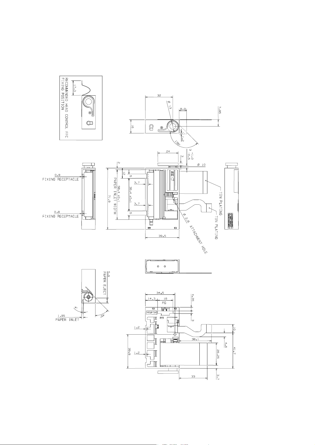
Figure 7-1 LTP1245R-C384-E Appearance and Dimensions
Unit : mm
Tolerance: ±0.5 mm
7-2
Page 59
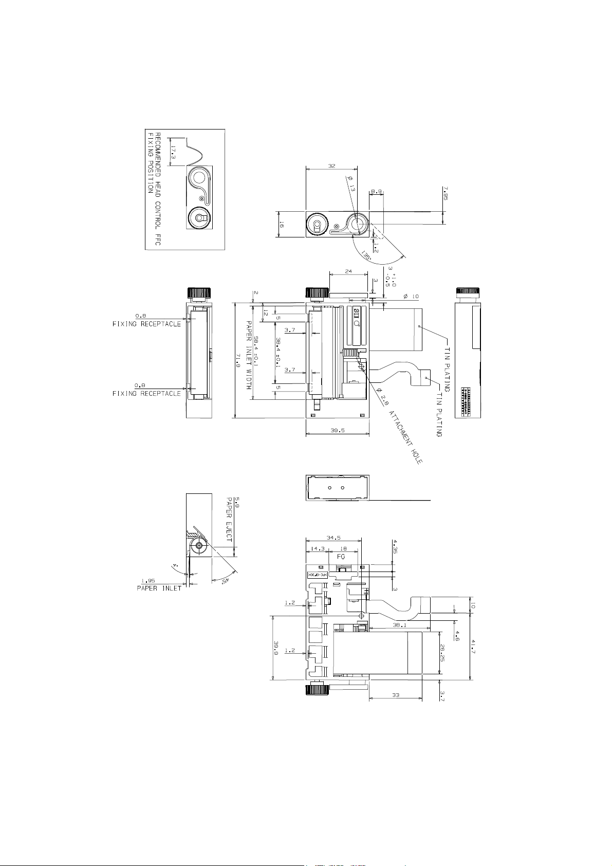
Figure 7-2 LTP1245S-C384-E Appearance and Dimensions
Unit : mm
Tolerance: ±0.5 mm
7-3
Page 60
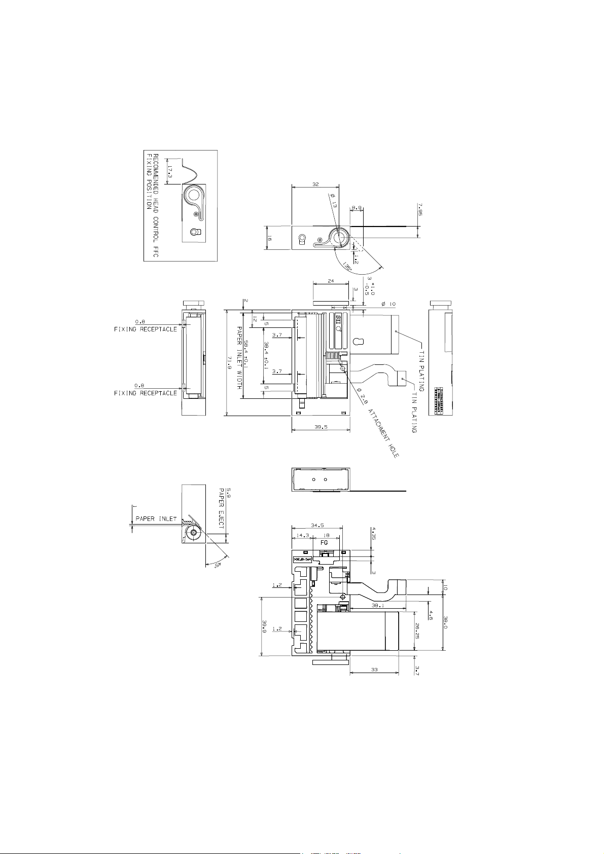
Unit : mm
Tolerance: ±0.5 mm
Figure 7-3 LTP1245T-S384-E Appearance and Dimensions
7-4
Page 61
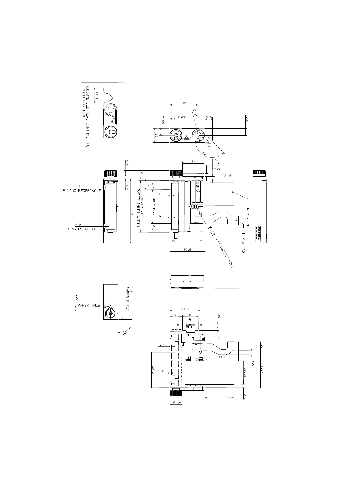
Unit : mm
Tolerance: ±0.5 mm
Figure 7-4 LTP1245U-S384-E Appearance and Dimensions
7-5
Page 62

7-6
Page 63

CHAPTER
LOADING/UNLOADING PAPER AND HEAD CLEANING
8.1 LOADING/UNLOADING PAPER PRECAUTIONS
①①①① Loading paper
Load paper with the thermal head in the up position.
(See Figure 8-1 Head Cleaning Procedure (b) in Section 8.2 “HEAD CLEANING
PROCEDURES AND PRECAUTIONS”).
Cut the edge of the paper so that the center of the paper will be inserted first
8
GOOD
NO GOOD NO GOOD NO GOOD
Insert the paper straight into the paper inlet.
When the edge of the paper comes up from between the thermal head and the platen, pull the
edge of the paper, check whether the paper is aligned correctly, and place the thermal head into
the down position.
②②②② Unloading paper
Unload paper with the thermal head in the up position.
(See Figure 8-1 Head Cleaning Procedure (b) in Section 8.2 “HEAD CLEANING
PROCEDURES AND PRECAUTIONS”).
Pull the paper straight up by hand in the direction in which the paper is normally fed.
If the paper is bonded on the core of the paper roll, separate the paper from the core and then pull
the paper out.
8-1
Page 64

③③③③ Auto-loading paper
Cut the edge of the paper so it is vertical to the direction of the paper feed.
NO GOOD
GOOD NO GOOD
NO GOOD
Load paper with thermal head in the down position.
If the paper skews, place the thermal head in the up position and reset the paper.
If the thermal head has been in the down position for a long time, it will be impossible to insert
because the head is in contact with the platen. In this case, place the head in the up position once
and insert the paper again.
8-2
Page 65
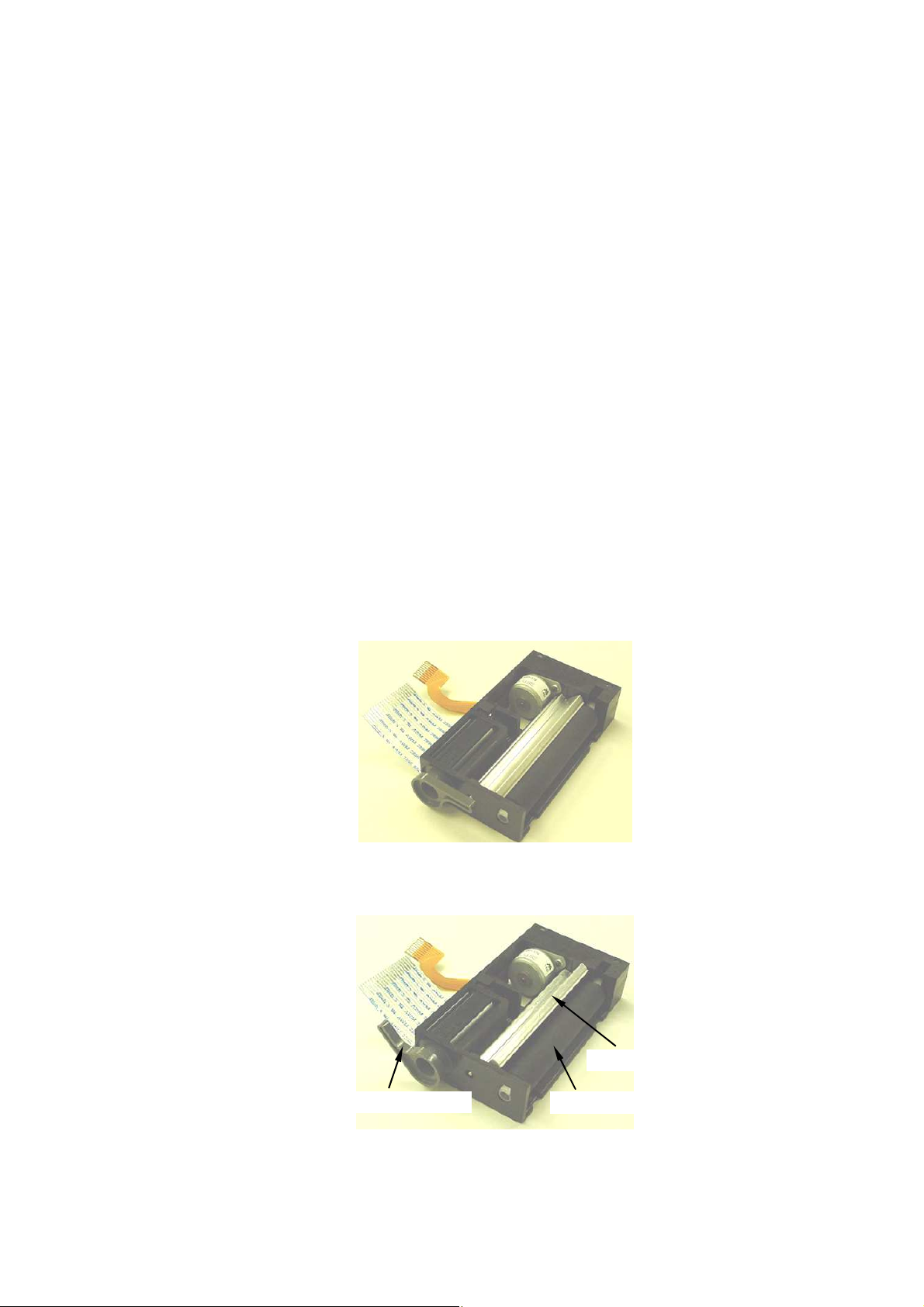
8.2 HEAD CLEANING PROCEDURE AND PRECAUTIONS
PROCEDURE :
①
Lift the head up lever (a) so it stands upright (b).
②
Clean the heat elements using alcohol and a cotton swab.
③
After cleaning, set the head up lever to its original position by reversing the steps.
PRECAUTIONS :
①
Do not clean the thermal head immediately after printing bacause thermal head will still be hot.
②
Cleaning fluid: ethyl alcohol, isopropyl alcohol.
③ Do not use sandpaper, cutter, etc. when cleaning. They will damage the heat elements.
④
Do not start printing operation until alcohol dries.
(a)
(b)
HEAD UP LEVER PLATEN ROLLER
Figure 8-1 Head Cleaning Procedure
8-3
HEAT ELEMENT
Page 66

8-4
Page 67

CHAPTER
9
PERIPHERAL EQUIPMENT
9.1 AUTOCUTTER UNIT
The LTP1245 can be equipped with the ACU6205 autocutter unit.
The ACU6205 autocutter unit uses the circular cut method.
The circular cut method enables the ACU6205 autocutter unit to be compact and lightweight.
For the specifications and the mechanism of how the ACU6205 operates, see the ACU6205
AUTOCUTTER UNIT TECHNICAL REFERENCE.
9-1
Page 68
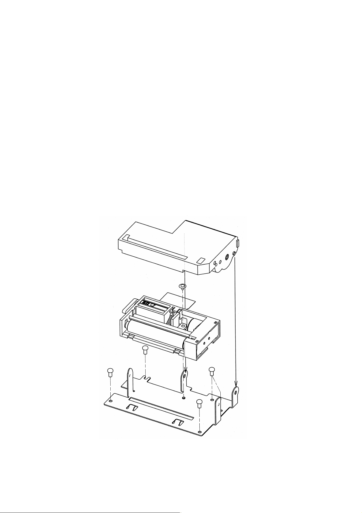
①
9.1.1 Installation
(1) When Using a Special Mount
1) Secure the printer on the special mount (OP-L1200-E) with the special screws.
①
2) The recommended tightening torque is 3 kgf cm (
3) Use four screws to secure the mount on the cabinet. Recommended screws: M2.6 (②
in Figture 9-1).
4) Connect the FPC and FFC of the printer to the main unit.
5) Install the ACU6205 autocutter unit from the grounding plate side (③,④ in Figure 9-1).
6) Connect the cutter leads.
in Figure 9-1).
④
③
②
②
②
②
Figure 9-1 Installation
9-2
Page 69
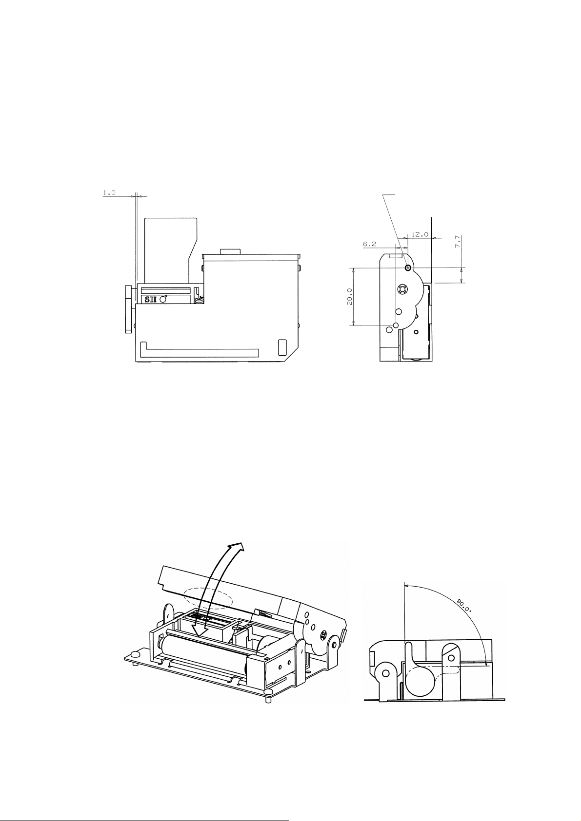
(2) When Designing a Mount
Design a mount so that the fulcrum for rotation is located as shown in Figure 9-2.
Fulcrum for rotation
Figure 9-2 Designing a Mount
9.1.2 Opening and Closing the Autocutter Unit
Open the autocutter unit to insert sheets of paper manually or to clear paper jams. To open the
autocutter unit, lift the part shown in Figure 9-3. Care should be taken to avoid causing damage to the
platen. Before closing the autocutter unit, verify that the print head is down. Close the autocutter unit
until it clicks.
Note 1: Do not raise the head when the autocutter unit is closed. Set the head up lever to the position
shown in Figure 9-4 to clear paper jams.
Figure 9-3 Opening and Closing of Autocutter Unit Figure 9-4 Head up Lever Position
9-3
Page 70

9.1.3 Inserting Recording Paper
(1) Automatic paper insertion
Paper can be inserted automatically with the autocutter unit closed.
See ③ in Section 8.1, LTP1245 LINE THEMAL PRINTER MECHANISM TECHNICAL
REFERENCE.
(2) Manual paper insertion
Open the autocutter unit and insert paper.
See ① in Section 8.1, LTP1245 LINE THERMAL PRINTER MECHANISM TECHNICAL
REFERENCE.
After the printer setup, insert the paper into the paper feed slit in the autocutter, then close the
autocutter unit.
(3) Recording paper removal
With the autocutter unit closed, turn the head up lever to the position shown in Figure 9-4,
release the head and pull the paper out straight.
For information on how to clear paper jams, see Section 9.1.4.
9.1.4 Clearing Paper Jams
If a paper jam occurs, clear it as follows:
1) Turn off the printer and the autocutter.
2) Open the autocutter unit and remove the jammed paper.
For information on paper jams in the autocutter, see CHAPTER 5, "CANCELING MOTOR
(MOVABLE EDGE) LOCK IN THE "ACU6205 AUTOCUTTER UNIT TECHNICAL
REFERENCE".
9-4
Page 71
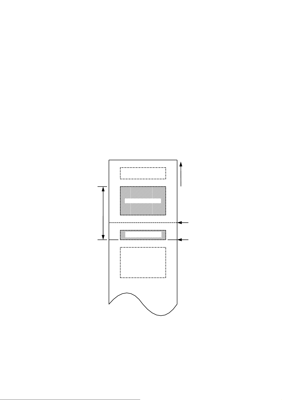
9.1.5 Hints for Use
PRINT AREA B
(1) Do not back feed paper after cutting paper using the autocutter unit because it will cause a paper
jam.
(2) To prevent paper from jamming, feed paper or print feed more than 3 mm after cutting paper.
(3) To make the most efficient use of paper, as shown in Figure 9-5, print area A for the next print
portion after printing area B, and then cut the paper.
(4) If a partial cut is performed, the backlash absorption steps (40-step reverse rotation and 40-step
normal rotation) should be included when printing starts after cutting paper (after pulling paper).
INITIAL
PRINTING AREA
PRINT AREA A
PRINT AREA A
PRINT AREA B
PAPER FEED DIRECTION
CUT POSITION
PRINT START POSITION
* Do not print on the cut position.
Figure 9-5 Best Cutting Position for Efficient Paper Use
9-5
Page 72
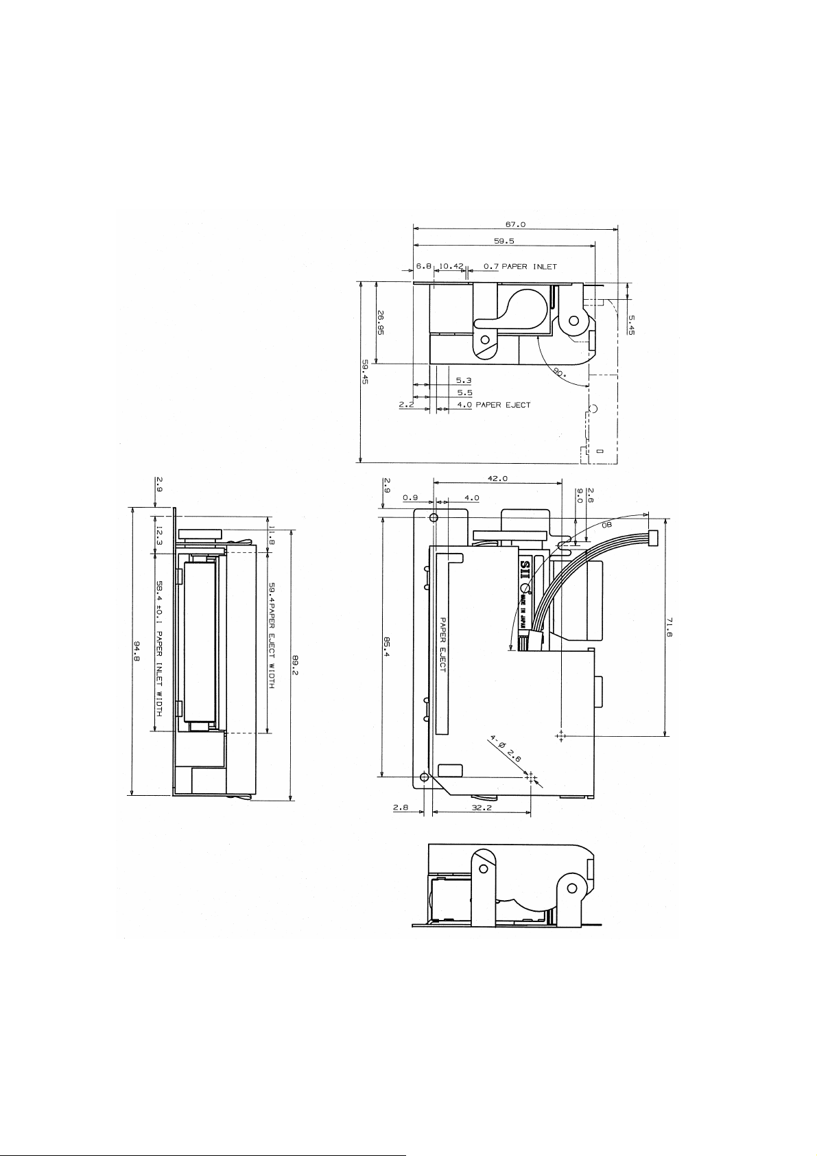
9.1.6 External View when the LTP1245 is equipped with the Autocutter
unit: mm
Figure 9-6 External View when the LTP1245 is equipped with the Autocutter
9-6
Page 73
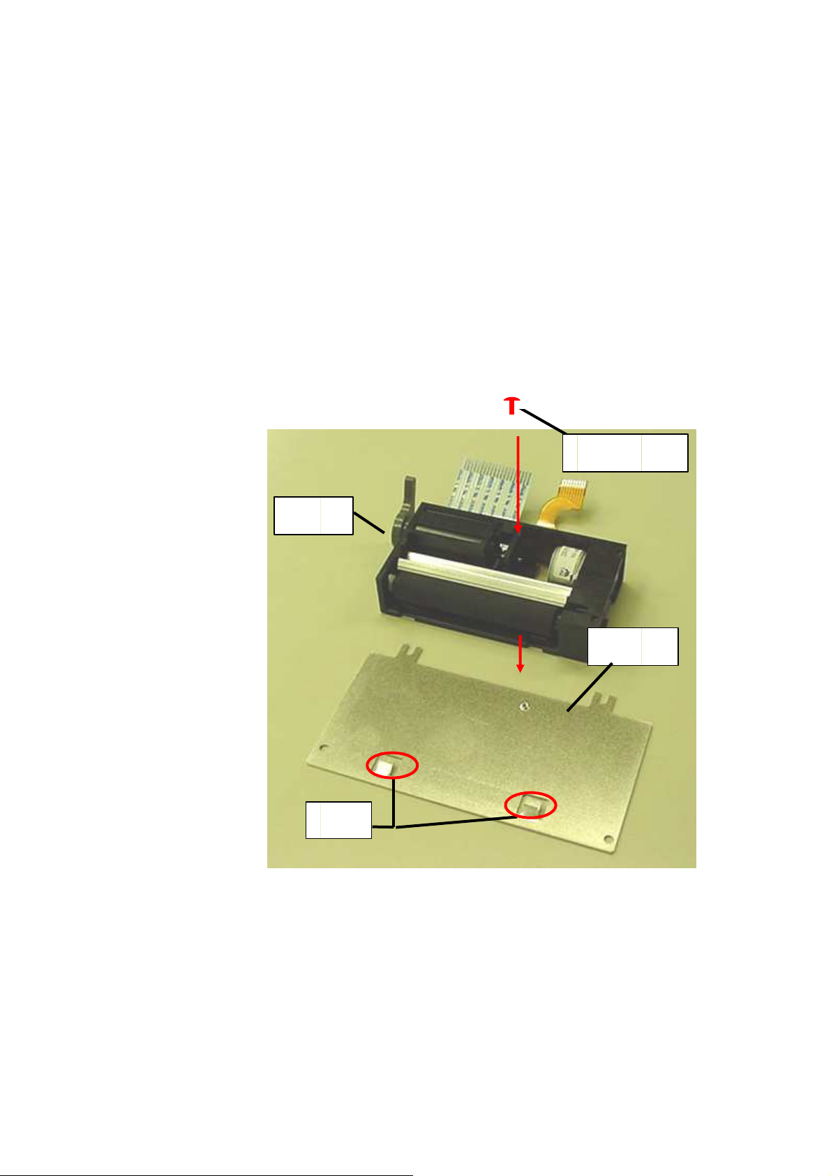
9.2 LTP1245 MOUNT (OP-L1245A-E)
The LTP1245 can be secured on the cabinet using the LTP1245 mount (OP-L1245A-E) and four
screws.
9.2.1 Installation
Align the two notches of the printer with the tabs on the LTP1245 mount (OP-L1245A-E) and secure the
printer by installing a special screw (No.0 cross-recessed machine screw; tightening torque:
3 kgf • cm) in the printer installation hole. (2.8 mm diameter) (Figure 9-7).
LTP1245R
Tabs
Special
screw
OP-L1245A-E
Figure 9-7 LTP1245 Mount Installation
9-7
Page 74
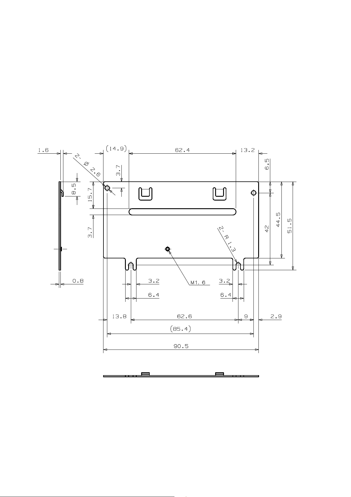
9.2.2 OP-L1245A-E External View
Unit:mm
Figure 9-8 LTP1245 Mount External View (OP-L1245A-E)
9-8
 Loading...