

Page 1
FLAT
BED
MACHINES
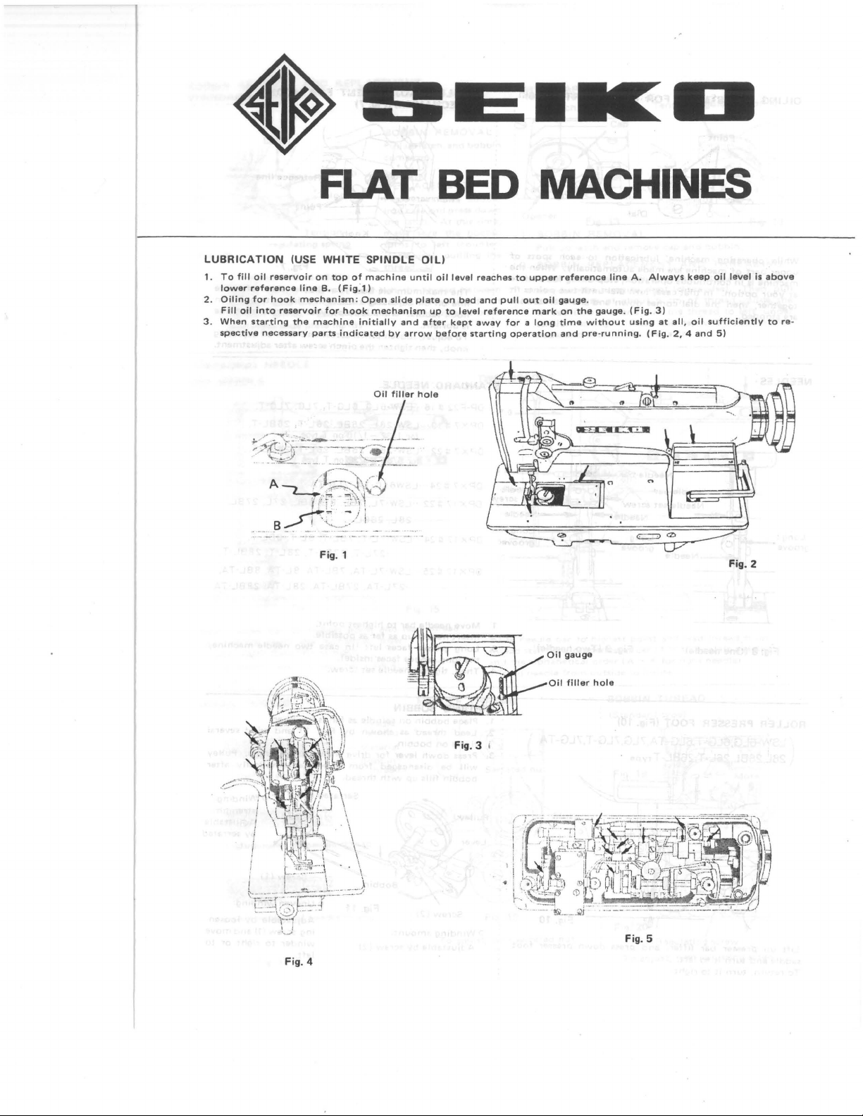
LUBRICATION
1.
To
fill
oil
2.
3.
lower
Oiling
Fill
When
spective
reference
for
oil
into
starting
reservoir
hook
necessary
(USE
WHITE
on
top
line
B.
mechanism: Open
reservoir
the
for
machine
parts
Fig. 1
SPINDLE
of
machine
(Fig:l)
hook
initially
indicated
until
slide
mechanism
and
by
arrow
Oil
filler
OIL)
plate
after
hole
oil
up
before
on
to
level
bed
level
kept
reaches
and
reference
away
starting
to
upper
pull
out
mark
for a long
operation
oil
Oil
reference
gauge
.
on
the
time
without
and
pre-running.
gauge
line
A.
gauge. (Fig.
using
Always
3)
at
(Fig.
keep
all,
oil
2, 4 and
oil
level
sufficiently
5)
Fig. 2
is
above
to
re-
Fig. 4
Fig. 3 1
Oil
filler
hole
Fig. 5
Page 2

BOBBIN
STANDARD
Bobbin
case
Opener
Fig.
12
3 .
THREADING
Guide
bobbin
tension
and
REMOVAL
TYPE
Latch
regulating
thread
case
spring.
close
slide
AND
REPLACEMENT
Bobbin
Slot
Tension
spring
BOBBIN
into
slot
and
opener,
Leave
plate
lightly.
1.
BOBBIN
Pull
comes
2.
BOBBIN
REPLACEMENT
Place
into
the
make
turns
clockwise),
thread
and
pull
and
pass
about 5 em
up
threaded
case
latch.
sure
to
.
the
thread
from
REMOVAL
latch,
up.
and
left
thread
and
·press
At
this
the
(counter
pullling
between
inside
needle
bobbin
bobbin
down
time,
bobbin
the
plate
of
·
WITH
;
Opener
:
1.
BOBBIN
Pull
:
2.
BOBBIN
Place
sura
out a length
thread
tension
hook
CAP
Latch
up
threaded
bobbin
and
latch
into
spring.
Fig.
13
REMOVAL
and
remove
REPLACEMENT
bobbin
turns
to
right
of
about 5 em
slot
and
pull
Place
press
down
the
Tension
~
'.~)
,
I
regulating
~
spring
----
~-
~
~Slot
c·\
/:/'
_v
~
Fig.
cap
and
bobbin.
AND
Into
the
the
latch.
THREADING
cap.
At
of
thread
cap
this
thread,
with
(clockwise).
to
bobbin
time,
Then,
guide
left,
make
under
14
pull
the
into
THREADING
ONE
NEEDLE
o Raise
from
Thread
o A
(pre-tension
TA
tVPe.
THREAD
~~~==~~~~=~
~--Material
needle
thread
needle
TENSION
Perfect
NEEDLE
bar
to
stand
the
from
left
disc)
is
stitching
highest
numerical
to
right.
only
for
---_Bobbin
point
LSW·6LG,
Needle
thread
thread
and
order
Fig.
lead
.
7LG,
NEEDLE
15
thread
T,
TWO
7.G+-IH---
6
F'
'
5, E
0
Raise
thread
and
Thread
THREAD
NEEDLE
-t-#1r-"<iJ~IE!;!j
-4~1--·-+tJ
needle
stand
the
alphabetical
needle
bar
the
from
~'-'
·
to
highest
numerical
order
outside
/1..-1."\\
point
order
(A-K for
to
BOBBIN
(Standard
and
( 1
~
inside.
THREAD
type)
Fig. 19
lead
11
right
for
needle)
Fig.
thread
left
16
from
needle)
.
Tight
tension
of
needle
thread
Loose
tension
of
needle
Fig.
thread
To
17
adjust,
Fig.
turn
18
serrated
nut
More
Fig.
20
....s...:~:::.........
Regulating
To
adjust,
-
-
-f:O;:;.:"
screw
turn
adjusting
screw
Page 3

OILING
While
upper
machine
at
your
together,
are
stopped.
ADJUSTMENT
Point
operating
part
of
machine
is
in
continuous
option.
then
In
the
machine,
are
that
dial
FOR UPPER
lubrication
made
automatically.
operation,
case,
turn
comes
down
stop
dial
until
and
PART
to
each
oiling
the
(Fig.
Fig. 6
spots
When
for a while
two
points
lubrications
61
of
the
fit
OILING
MECHANISM
The
maximum
line
on
oil
hook
saddle. While
is
upright.
To
adjust,
knob,
then
ADJUSTMENT
(fig.
7)
oil
flow
adjusting
loosen
tighten
it
pinch
the
knob
stops
pinch
is
available
is in a
screw
FOR
when
and
screw
HOOK
when
line
the
turn
after
reference
with
point
reference
oil
adjusting
adjustment
on
line
.
NEEDLES
Long
groove
Fig. 8 (One needle)
ROLLER
PRESSER FOOT (Fig. 10)
Fig. 9
Jfoii~~--Long
(Two
LSW-6LG,6LG-T,6LG-TA,7LG,7LG-T,7LG-TA )
(
26L,26BL,26L-T,26BL-T
type
l+o---Needle
groove
needle)
STANDARD
DP·F22 # 16
OPX7 # 19
OPX7
OPX7
OPX 17
OPX
17
OPX 17
1.
Move
Insert
Long
the
Then,
long
needle
needle
groove
tighten
2.
3.
4.
WINDING
1.
Place
Lead
times
Press
will
bobbin
bobbin
thread
on
down
be
2.
3.
NEEDLE
..
·LS
..
·LSW·26L. 26BL.
for
#22
..
·LSW·26L,
for
5/64' -3/32' on T type
#24
..
·LSW6LG·TA.
#22
..
·LSW·7L,
28L,
#24
..
·LSW·7L·T.
#25
..
·LSW·7
·
27L·TA, 27BL
bar
up
faces
groove
faces
needle
BOBBIN
on
as
bobbin
.
lever
disengaged
fills
up
with
W·6LG. 6LG·T.
1/32'-1/16'on T type
26BL.
78L, BL.
28BL
·27L·T.
L·TA, 7BL·TA, BL·TA.
to
highest
as
far
as
possible
left
(In
inside)
set
screw
spindle
as
shown
by
for
drive
from
thread.
7LG
.
7BL·T,
27BL·T.
point.
case
.
far
Fig.
then
V·belt
7LG.
26L·T.
26L·T,
·TA
BBL.
BL·T,
·TA.
.
two
.
as
it
11
start
automatically
7LG·T,
26BL·T
26BL
·T.
27L,
27BL.
BBL·T
,
28L·T.
28BL·T
BBL·TA.
28L
·TA,
28BL·TA
needle
machine,
will go.
and
wind
machine. Pulley
0
Winding
strength
Adjustable
by
nut.
.
.
several
after
:
serrated
Fig.
10
o
Lift
saddle
To
return,
up
presser
and
turn
turn
bar
lifter,
and
press
down
presser
it
to
left.
It
to
right.
foot
Winding
Adjustable
Screw
(2)
amount
by
:
screw
Fig.
(2)
11
o
Uneven
Adjustable
ing
screw
winder
left
.
winding:
by
(1)
and
to
right
loosen
move
or
·
to
Page 4

TO
REGULATE
PRESSER
FOOT
PRESSURE
ADJUSTING
PRESSER
(Compound
LIFT
FEEl'
feed
OF
ALTERNATING
mechanism
only)
More
"
_;.~
::-o_-
:
::·.-~=-
~
·
...
.
:_l=~~::-.-::
The
pressure
·.
o~
. 'i>osslble, '
f~eding.
'
ADJU~TI!'IG
Pressing
you.
mechanism. Hold
pulley
number
Then,
down
Then
either
on
release
while
·
STITCH
button
plunger
forward
pulley
the
plunger
the
still
~1?
..
~-
~-:;:L~_
-_
f
'r'
.
~-:
~ ~~-:-
.
Fig. 21
material
sufficient
LENGTH
A,
turn
enter
or
.
pulley
Into
plunger
rearward
come
will
the
may
)
-
should
to
down
at
Less
insure
slowly
notch
so ·that
mark
be
as
in
feeding
and
on
light
correct
toward
turn
desired
arm
as
.
To
adjust, Loosen
stud
assembly
REVERSE
(only
with
Pr
ess
down
along
STITCHING
reverse
mechanism)
lever
as
far
wing
slot
as
nut
.
it
will go .
and
move
link
and
RE
-SE:r
SAFETY
Fig
;
25
'
VARIETY: Available
CLUTCH
(C)•(BT)•(FL)
MECHANISM
. ' .
SEIKO
11 Tel.: (03)
Cable
1.
Remove
in
2.
Pressing
to
•
Operating
any
hook. Do
button B and
return
safety
pressure
•
SEWING MACHINE CO.,LTD.
3,
lmado 1-chome,
872-6171-7,7288
Address: "SEIKOSEWMCO" TOKYO
Taito-ku,
Telex: 2657148
Tokyo,
foreign
not
use
clutch.
of
111
matter
any
sharp-edged
turn
the
safety
Japan.
SEIKO
which
pulley
clutch
J
may
have
tools
rearward
can
.
be
lodged
slowly
changed
.
96035000- (E)
 Loading...