

Page 1
24-pin Dot-matrix Printer
FB-90
OWNER'S MANUAL
0
Page 2

1. No part of this manual may be reproduced in any form.
2. This manual is subject to change without notice.
3. This manual was prepared with the greateset care. If you should find any unclear points,
mistakes, or omissions, please contact us.
4. We will not bear any responsibility for unsatisfactory results from the use of this printer
despite item 3 above.
* EPSON is a registered trademark of S.Epson Corporation.
* LQ-2550 is a registered trademark of S.Epson Corporation.
* IBM is a registered trademark of International Business Machines Corporation.
* IBM 2391 is a registered trademark of International Business Machines Corporation.
* HP is a registered trademark of HEWLETT-PACKARD Company.
* PCL is a registered trademark of HEWLETT-PACKARD Company.
* DeskJet 500 / RuggedWriter 480 are registered trademarks of HEWLETT-PACKARD
Company.
* Windows is a registered trademark of Microsoft Corporation.
Copyright © 1999 SEIKO Precision Inc.
Warning
This equipment has been tested and found to comply with the limits for a Class B digital
device, pursuant to Part 15 of the FCC Rules. These limits are designed to provide
reasonable protection against harmful interference in a residential installation. This
equipment generates, uses, and can raditae frequency energy and, if not installed and
used in strict accordance with the instructions, may cause harmful interference to radio
communications. However there is no guaratee that interfernce will not occur in a
particular installation. If this equipment does cause harmful interference to radio or
television recption, which can be determined by turning the equipment off and on, the
user is encouraged to try to correct the interference by one or more of the following
measures:
— Reorient or relocate the receiving antenna
— Increase the separation between the equipment and receiver.
— Connect the equipment into an outlet on a circuit different from that to which the
receiver is connected.
— Consult the dealer ro an experienced radio/TV technician for help.
“It is necessary to use shielded interconnect cables to insure compliance with FCC Class
B limits for radio frequency emissions.”
Caution : Changes or modifications not expressly approved by the party responsible for
compliance could void the user’s authority to operate the equipment.
Page 3

1. No part of this manual may be reproduced in any form.
2. This manual is subject to change without notice.
3. This manual was prepared with the greateset care. If you should find any unclear points,
mistakes, or omissions, please contact us.
4. We will not bear any responsibility for unsatisfactory results from the use of this printer
despite item 3 above.
* EPSON is a registered trademark of S.Epson Corporation.
* LQ-2550 is a registered trademark of S.Epson Corporation.
* IBM is a registered trademark of International Business Machines Corporation.
* IBM 2391 is a registered trademark of International Business Machines Corporation.
* HP is a registered trademark of HEWLETT-PACKARD Company.
* PCL is a registered trademark of HEWLETT-PACKARD Company.
* DeskJet 500 / RuggedWriter 480 are registered trademarks of HEWLETT-PACKARD
Company.
* Windows is a registered trademark of Microsoft Corporation.
Copyright © 1996 SEIKO Precision Inc.
Warning
This equipment has been tested and found to comply with the limits for a Class B digital
device, pursuant to Part 15 of the FCC Rules. These limits are designed to provide
reasonable protection against harmful interference in a residential installation. This
equipment generates, uses, and can raditae frequency energy and, if not installed and
used in strict accordance with the instructions, may cause harmful interference to radio
communications. However there is no guaratee that interfernce will not occur in a
particular installation. If this equipment does cause harmful interference to radio or
television recption, which can be determined by turning the equipment off and on, the
user is encouraged to try to correct the interference by one or more of the following
measures:
— Reorient or relocate the receiving antenna
— Increase the separation between the equipment and receiver.
— Connect the equipment into an outlet on a circuit different from that to which the
receiver is connected.
— Consult the dealer ro an experienced radio/TV technician for help.
“It is necessary to use shielded interconnect cables to insure compliance with FCC Class
B limits for radio frequency emissions.”
Caution: Changes or modifications not expressly approved by the party responsible for
compliance could void the user’s authority to operate the equipment.
Page 4
OWNER'S MANUAL
1999 SEIKO Precision Inc.
C
24-pin Wide-Carriage
Dot Matrix Printer
FB-900
As an ENERGY STAR Partner, SEIKO Precision Inc. has determined that this product meets
the ENERGY STAR guidelines for energy efficiency.
- Outline of the International ENERGY STAR Office Equipment Program -
The International ENERGY STAR Office Equipment Program is an international program
that promotes energy saving through the use of computers and other office equipment. The
program backs the development and dissemination of products with functions that effectively
reduce energy consumption. It is an open system in which business proprietors can participate
voluntarily. The targeted products are office equipment such as computers, displays, printers, facsimiles,
and copiers. Their standards and logos uniform among participating nations.
Page 5

How to use this maunal
This manual describes the operation procedures for the 24-Pin Wide-Carriage Dot
Matrix Printer. Read through this manual before using the printer. Keep this
manual near the printer and refer to it whenever necessary.
Sections 1 and 2 describe the basic procedures, including unpacking, setup and
key operations. Install and setup the printer as described in these sections.
Section 3 and subsequent sections describe the functions and software commands
of the printer. Refer to these sections when necessary.
This manual is organized as shown below.
1. Setting up the printer
2. Control panel operations
3. Setup options
4. Functions
5. Bar code and enlarged character function
6. Troubleshooting
7. Interface specifications
8. Software commands
9. Software setup functions
10. Specifications
11. Character set table
Index
Software command list
Read this manual thoroughly to use the printer properly.
—How to use this manual—
Precautions for use
Organization of this manual
Page 6
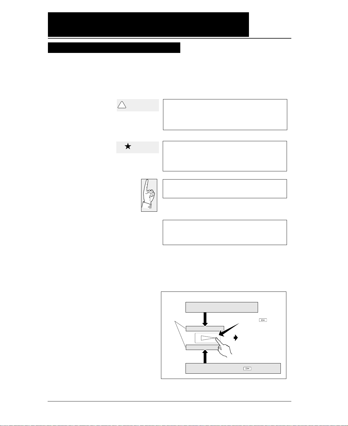
Symbols used in this manual
How to use this maunal
A caution symbol
Care should be taken in order to operate the
printer correctly.
This symbol indicates a note that is useful for
operation.
1.
2.
3.
These item numbers show the sequence of
operation. Perform the operations in the
order shown.
The symbols used in this manual have the following meanings.
—How to use this manual—
This symbol indicates that personal injury
may occur if this caution warning is ignored.
!
CAUTION
Caution
Display on the LCD before
the key is pressed
Display on the LCD
1. MULTIPART
2.HEAD ADJUSTMENT
Display on the LCD after the key is pressed
Press the key.
To the next step
Page 7

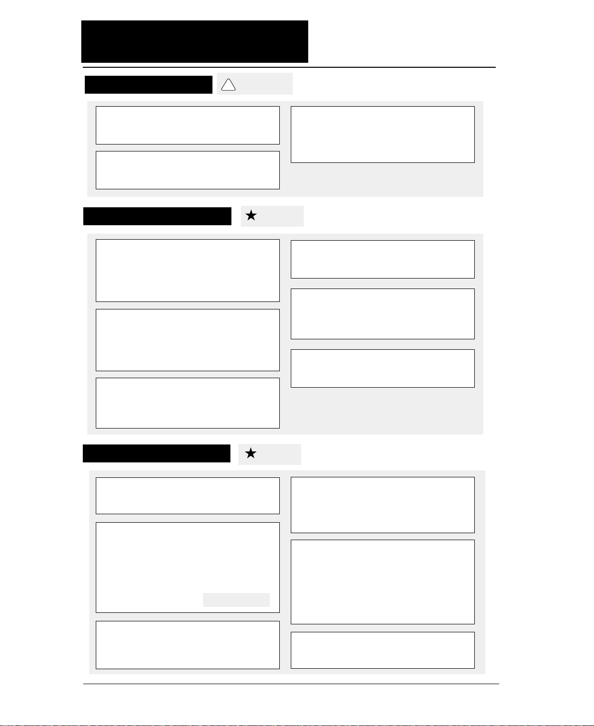
Contents
Preface
How to use this manual
Cautions for use
Organization of this manual
Symbols used in this manual
● Major functions..................................... i
● Cautions................................................. iv
Safety Cautions............................
iv
Cautions in setting up..................
iv
Cautions in operation...................
iv
● Unpacking the printer......................... v
Unpacking the printer................. vi
● Dimensions........................................... vii
● Components and functions................ viii
Appearance of the printer...........
viii
Components and functions.........
ix
Operation panel explanation 1.. x
Operation panel explanation 2. xi
Options and consumables....... xii
Maintenance............................ xiii
1. Setting up the printer...................... 1-1
● Connecting the printer to
the power source.................. 1-1
● Installing the ribbon cassette........... 1-2
Installing the ribbon cassette..1-2
● Paper path............................................ 1-4
Path of fanfold paper................ 1-4
Path of cut sheet paper............ 1-5
● Selecting the paper path.................... 1-6
● Paper..................................................... 1-8
● Selecting the paper form
..................1-10
● Loading fanfold paper
(Front tractor)
..........................1-12
(Rear tractor)............................ 1-16
● Loading cut sheet paper
(Manual paper feeding)............ 1-19
● Printing using the cut sheet feeder
(Optional)
.............................1-22
● Running the self-test.......................1-27
● Connecting the printer to
the computer...........................1-28
Parallel interface....................1-28
Serial interface.......................1-29
● Input data hexadecimal dump list...1-30
● Link between paper path (PATH)
and paper form (MEMO)..........1-31
2. Control panel
operations
......................... 2-1
● Control panel operations................... 2-1
Control panel............................ 2-1
Fuction keys............................. 2-1
LCD........................................... 2-5
3. Setup options.................................... 3-1
Outline of the
setup modes..... ......3-1
Available function in the
setup modes........... 3-1
Entering the setup
modes.................... 3-1
● Operations on the setup mode...........3-2
Keys for setting......................... 3-2
Setting example in EXTENDED
SETUP MODE.... 3-3
● Setup mode summary (1).................. 3-4
● Setup mode summary (2)
.................. 3-5
● Factory default setting..................... 3-6
#01 Multipart............................................. 3-8
#02 Head adjustment............................... 3-9
#03 TOF adjustment.............................. 3-10
#04 Page length..................................... 3-11
#05 Paper width..................................... 3-12
#06 Top margin..................................... 3-13
#07 Bottom margin............................... 3-14
#08 Left margin..................................... 3-15
#09 Right margin................................... 3-16
#10 Character quality............................ 3-17
#11 Character font................................. 3-18
#12 Character pitch............................... 3-19
#13 Line feed pitch................................ 3-20
#14 Enlarging/Reducing print.............. 3-21
#15 Paper Fastener................................ 3-22
#16 Perforation...................................... 3-22
#17 Fanfold feed.................................... 3-23
#18 Paper Quality.................................... 3-23
#19 Saving data in format memory...... 3-24
#20 Loading data from format
memory................................ 3-24
#20 Emulation........................................ 3-25
#21 Character table (HP)....................... 3-25
#22 Character table (EPSON)............... 3-26
#23 Character table (IBM).................... 3-26
Page 8

#24 National font (EPSON).................. 3-27
#25 Code page...................................... 3-28
#26 Alternate graphics mode (AGM)
(IBM).................................. 3-28
#27 CR code function............................ 3-29
#28 LF code function............................ 3-29
#29 Accent character............................ 3-30
#30 Zero font style................................ 3-30
#31 Horizontal tab................................ 3-31
#32 Locking page length...................... 3-31
#33 Locking font................................... 3-32
#34 Locking character pitch................. 3-32
#35 Locking character quality.............. 3-33
#36 Locking character table.................. 3-33
#37 FF code function / TOF ................. 3-34
#38 Graphic Quality.............................. 3-35
#40
Validity of bar code and
enlarged character
................ 3-36
#41
Bar code type
................................... 3-37
Bar code specifications.........
3-38
#42 Bar code size................................... 3-39
#43 Enlarged character size.................. 3-39
#44 Software setup................................ 3-40
#50 PCL mode (HP).............................. 3-40
#51 Secondary character table (HP).... 3-41
#60 Setting option.................................. 3-41
#61 Paper path....................................... 3-42
#62 Automatic scrolling........................ 3-42
#63 Out-of-paper detection.................... 3-43
#64 Skew detection............................... 3-43
#65 Paper jam detection....................... 3-44
#66 Line feed speed.............................. 3-44
#67 Auto scroll position........................ 3-45
#70 Interface.......................................... 3-46
#71 Printer select command................... 3-47
#72 Parity bit (Serial I/F)................... 3-47
#73 Data length (Serial I/F)............... 3-48
#74 Stop bit (Serial I/F)...................... 3-48
#75 Protocol (Serial I/F)..................... 3-49
#76 Baud rate (Serial I/F)................... 3-49
#77 Serial error (Serial I/F)................ 3-50
#78 CTS signal (Serial I/F)................. 3-50
#79 CD signal (Serial I/F)................... 3-51
#80 DSR signal (Serial I/F)................. 3-51
#81 Input buffer size.............................. 3-52
#82 BUSY/ACK signal timing
(Parallel I/F)....................... 3-53
#83 Data latch timing
(Parallel I/F)....................... 3-53
#84 Error Status (Parallel I/F)............... 3-54
#90 Printing direction........................... 3-55
#91 Display language on LCD............. 3-55
#92 Locking panel keys........................ 3-56
#93 Locking reset key........................... 3-56
#94 Printing panel setting..................... 3-57
#95 Printing setup list........................... 3-57
4. Functions........................................ 4-1
● High speed printing............................. 4-1
● Enhancing the copying capability
for multipart forms................. 4-2
● Setting the printing start position........ 4-2
● Feeding perforation to the cutter
position................................... 4-3
● More stable paper feeding.................. 4-3
● Automatically feeding perforation to the paper
cutter position in the standby condition.. 4-4
● EEPROM initialization ...................... 4-5
● Correcting vertical misalignment........ 4-6
● Using various types of paper............... 4-8
● Executing test printing......................... 4-9
● Key shortcut function........................... 4-9
● Setting the application software......... 4-10
● Connecting the printer in the
HP envioronment................. 4-12
5. Bar code and enlarged
character function
................. 5-1
● Bar code type.......................................5-1
Outline of bar code function
........ 5-1
Makeup of bar code....................... 5-1
Presettable bar code function list.5-2
Bar code command list................. 5-2
(1) Bar code type.......................................... 5-2
(2) Element width........................................ 5-3
(3) Bar code height..................................... 5-3
(4) Setting HRI on and off........................... 5-3
(5) HRI font.................................................. 5-4
(6) Check character.................................... 5-4
Contents
Page 9

(7) Starting the bar code data sequence.... 5-4
(8) Ending the bar code data sequence.... 5-5
(9) Bar code data sequence......................... 5-5
(10) Printing density.................................... 5-5
(11) Guide bar expansion............................ 5-5
(12) Start and stop characters..................... 5-6
(13) Barcode rotational angle...................... 5-6
(14) Disabling HRI of the start
and stop characters................... 5-6
(15) Value input mode.................................. 5-6
(16) Initializing the bar code mode.............. 5-7
Additional explanation of bar code
commands................................. 5-7
◆
Data processing in the bar
code data sequence................... 5-7
◆
Printing bar codes..................................... 5-8
◆
HRI........................................................... 5-9
◆
Error processing...................................... 5-10
◆
Code 128 subset transition rule............. 5-11
◆
UPC-E conversion rule......................... 5-12
◆
Calculating the check character............ 5-12
◆
Other....................................................... 5-14
◆
Element printing.................................... 5-14
● Enlarged character function
........... 5-16
Outline of enlarged character
function................................... 5-16
Enlarged character command list.. 5-16
(1) Executing backspacing......................... 5-17
(2) Executing line feeding.......................... 5-17
(3) Executing form feeding........................ 5-18
(4) Executing carriage return..................... 5-18
(5) Initializing the
enlarged character mode........ 5-18
(6) Arrangement of enlarged characters..... 5-19
(7) Cell magnification for enlarged
characters............................... 5-19
(8) All-character set for enlarged
characters................................ 5-20
(9) Selecting an enlarged character font..... 5-20
(10) Height expansion for enlarged
characters................................ 5-21
(11) HMI for enlarged characters............... 5-21
(12) VMI for enlarged characters............... 5-22
(13) Setting and canceling the enlarged
character mode...................... 5-22
(14) Enlarged character cell offset............ 5-23
(15) Enlarged character pitch.................... 5-23
(16) Enlarged character quality.................... 5-24
(17) Enlarged character rotational angle..... 5-24
(18) Setting and canceling enlarged
character smoothing................. 5-25
(19) Enlarged character top offset............... 5-25
(20) Setting and canceling underlining
of enlarged characters.............. 5-26
(21) Enlarged character widthwise
expansition................................5-26
(22) Horizontal printing position for
enlarged characters.................. 5-27
(23) Vertical printing position for
enlarged characters.................. 5-27
◆
Enlarged character print samples.......... 5-28
6. Troubleshooting............................. 6-1
● Functional error messages
................ 6-1
● Operational error messages.............. 6-2
● Troubleshooting................................. 6-6
7. Interface specifications............... 7-1
● Parallel interface................................. 7-1
Input connector......................... 7-1
Pin configuration...................... 7-1
Timing chart.............................. 7-2
Input/output conditions............. 7-2
Signal explanations................... 7-3
Input signals to the printer........ 7-3
Output signals from the printer...7-4
● Serial interface
.................................... 7-5
Input connector........................ 7-5
Pin configuration...................... 7-5
Timing chart.............................. 7-5
Input signals to the printer........ 7-6
Output signals from the printer.. 7-7
Contents
Page 10

Handshaking protocol................ 7-8
DTR (READY/BUSY)
protocol..................7-8
X-ON/X-OFF (I)/(II) protocol. 7-9
Special notes............................ 7-10
ETX/ACK protocol................. 7-11
Baud rate................................. 7-11
Serial data organization........... 7-11
Automatic serial/parallel
selection.......................... 7-11
8. Software commands..................... 8-1
● EPSON Software command........... 8-1
● IBM Software command................. 8-9
● HP Software command
.................. 8-18
9. Software setup functions.......... 9-1
● Command format............................... 9-1
● Command
............................................ 9-2
10
. Specifications
................................ 10-1
● Printing specifications.......................10-1
● Print mode specifications.................. 10-2
● Graphic printing specifications.......... 10-5
● Throughput......................................10-5
● Paper specifications.......................... 10-6
● Other specifications.......................... 10-6
11. Character set table.................... 11-1
EPSON italic table...................................11-1
EPSON extenced graphic table...................11-1
EPSON international font table..................11-2
IBM character set table 1...........................11-2
IBM character set table 2...........................11-3
IBM all-character set table.........................11-3
Code page 437........................................ 11-4
Code page 850........................................ 11-4
Code page 857 ........................................11-4
Code page 860 .......................................11-4
Code page 863........................................ 11-5
Code page 865........................................ 11-5
ISO-1 (ISO-8859-1)..................................11-5
Code page 858.......................................... 11-5
Code page 861.......................................... 11-6
Code page BRASCII.................................11-6
Code page ABICOMP...............................11-6
ROMAN-8 character set (HP)....................11-7
PC-8 character set (HP).............................11-7
LEGAL character set (HP).........................11-7
MATH 7 character set (HP)........................11-7
LINE DRAW character set (HP).................11-8
International character set (HP) [ISO].........11-8
● Index
● Software command list
Contents
Page 11

i
◆ High-speed printing
Prining mode Pirnt speed Throughput
DRAFT (10 cpi) 603 CPS 206 LPM (132 columns)
LQ (10 cpi) 180 CPS 76 LPM (132 columns)
NLQ (10 cpi) 240 CPS 100 LPM (132 columns)
HQDR (10 cpi) 360CPS 135 LPM (132 columns)
S.D. (12 cpi only) 723 CPS 230 LPM (132 columns)
S.S.D. (15 cpi only) 904 CPS 270 LPM (132 columns)
◆ Original plus 8 multipart forms printing
The printer can print data on an original and up to eight
copies. Copy density can be enhanced by selecting the
DARK 1 (high pressure), DARK 2 (very high pressure) or
AUTO (automatic print pressure adjustment by sensing
the form set thickness). This setting is made in the
MULTIPART function of the SETUP MODE.
✽ : If DARK 1 or DARK 2 is selected, the printing
speed is reduced below the normal print speed
to compensate for the extra energy required
when printing in the high pressure print
modes.
◆ Bar code printing function
A variety of bar codes of this printer may be printed. The
narrow and wide spaces, narrow and wide bars, HRI,
check character, bar code height, and rotation may be
controlled with software commands. Customized bar
codes may also be printed using the element funcion.
Registered bar code formats: Industrial 2 of 5, Interleaved 2
of 5, Matrix 2 of 5, Codabar, Code11, Code 39 , Code 93,
Code 128, EAN-8, EAN-13, UPC-A, UPC-E, and Postnet
◆ Enlarged character printing
Characters can be enlarged (by up to 127 times as large x
127 times as large) using the enlarged character command
unique to this printer. Software commands are used for
control.
●●
Major functions
This printer provides a wide range of print functions, as shown below:
Page 12

ii
●●
Major functions
◆Zooming function (Batch enlargement or reduction printing)
◆ Cut sheet paper manually loading
◆ Skew sensor
A built-in skew sensor detects any cut sheets that are
skewed when loaded and ejects them.
◆ Automatic head adjustment
The printer employs an automatic paper thickness
detection sensor, instead of the conventional paper
thickness adjust lever, for optimum printing on all form
sets.
◆ Automatic loading (For fanfold or cut sheet paper)
◆ Perforation cutting (For fanfold paper)
By pressing the TEAR OFF key, the perforation of fanfold
paper is automatically fed to the paper cutter position.
◆ Paper parking (Switching fanfold paper and cut sheet paper)
If cut sheet paper is selected while fanfold paper is used,
the fanfold paper is automatically fed back to the parking
position (i.e., paper parking).
◆ Load adjustment
The pritning start position may be adjusted within a
range from approximately 0 to 26.7 mm from the top of
the paper. It is recommended that the printing position
be in the center of the paper in the range of 4 mm or less
from the the top of the paper.
◆ MICRO REVERSE LF and MICRO LF keys
These keys are useful for adjusting the printing start
position and paper cutting position.
◆Automatic scroll (For fanfold paper)
If no data input is recived for a preset period (0.5, 1, 5,
10, 15 sec.), the perfpration of the current page of fanfold
paper is fed to the paper cutter position.
Page 13

iii
◆Dual paper parking
If the optional rear tractor is used, two different types of
fanfold paper may be used. Software command or the
PAPER PATH key can be used for selection.
◆ Large 512KB communication buffer
◆ Setup memory for setting various functions on the LCD
◆ Ten resident fonts
◆ Line feed speed adjustment
Standard, 1/2 or 1/3 line feed speed is selectable for
stable paper feeding even when multipart paper is used.
◆ Vertical alignment function
◆ Serial data transfer at a maximum rate of 38.4k bps
◆ Parallel and serial interfaces are standard
Parallel and serial interface are switched automatically.
◆ Printing stops immediately if the printer cover is
inadvertently opened during printing.
◆ Enegy Star
Page 14
iv
●●
Caution
★ Unpack the printer. Make sure that the
printer body and all accessories are
included in the package and no parts are
damaged.
★ Do not use the printer in a location
exposed to direct sunlight or close to a
heater or other heat generating
equipment.
★ Before connecting or disconnecting the
interface cable, be sure to turn off the
printer.
★ Place the printer on a rigid, horizontal
base in a location that is free of vibration.
★ Do not use the printer in a dusty location
or any location subject to sudden
changes in temperature and humidity.
★ Do not connect the printer to a non-
standard power source.
★ Never try to print without a ribbon
cassette installed and paper loaded.
★ Do not turn off the printer during
printing, as this may lead to a
malfunction.
★
Take care not to twist the ribbon while
installing the ribbon cassette.
★
Push the lock levers of both tractors
to the LOCK positions firmly while
loading fanfold paper or single sheet
paper. It is for the purpose of
setting paper path securely.
★
If the case or cover becomes dirty,
clean it with a soft cloth moistened
with a small quantity of neutral
detergent diluted with water. Never
use a hard cloth or volatile solvent
such as alcohol, thinner, or benzine.
★ If any foreign matter gets into the
printer, turn off the printer
immediately and remove the foreign
matter.
Cautions in operation
Safety Cautions
Cautions in setting up
See page 3-1.
★ Use two hands and hold firmly at each
end when lifting the cut sheet feeder.
Personal injury can occur if the CSF unit
is dropped.
★ Do not touch the print head immediately
after printing because it is too hot.
★ Do not put your finger under the tractor
cover while loading fanfold paper.
!
CAUTION
Caution
Caution
Page 15
v
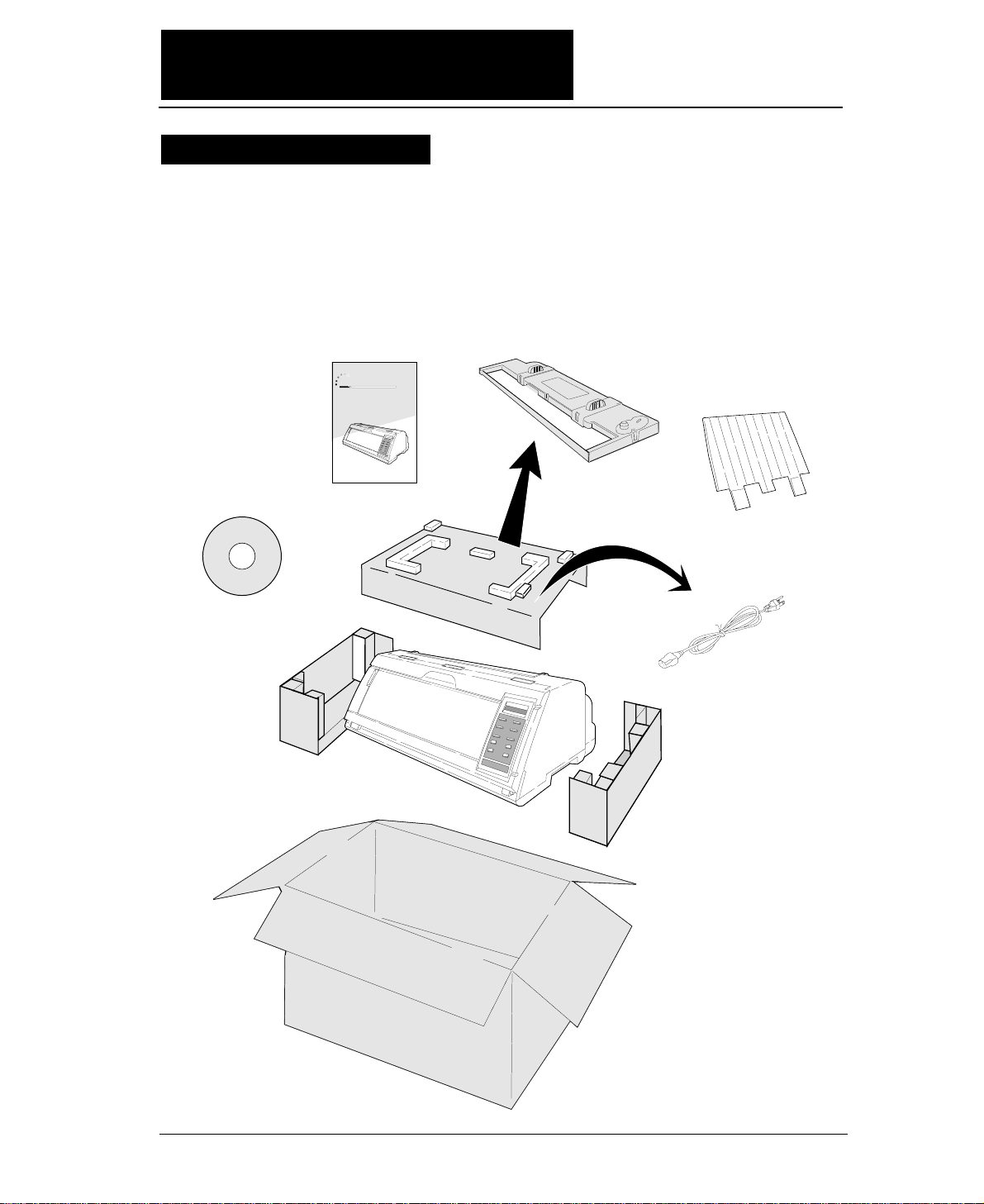
●
The printer body weights approximately 24 kg [52.9 lbs.]. It should be
taken out of the package by two or more persons.
Make sure that no parts of the printer are damaged.
●●
Unpacking the printer
Printer
Ribbon Cassette
Power Cord
24-pin Dot-matrix Printer
FB-900
Hand book
CD-ROM
Hand book
Top Paper Rack
Unpacking the printer
Page 16
vi
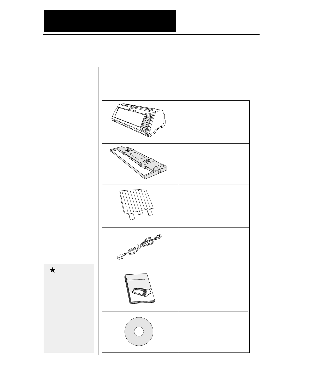
●●
Unpacking the printer
●
Check the carton for the following items:
■
Printer
■
Ribbon cassette
#SBP-1051
■
Power cord
Connect this power cord to an
AC outlet.
If some part is not
included in the package,
contact the dealer where
you purchased the
printer.
Keep the carton and
packaging material.
They are needed for
transporting the printer
or returning it for
service if ever required.
■
Top paper rack
Attach the top paper rack to
eject paper to the top of the
printer. Sheets of paper are
stacked on this rack.
■
Hand book
■
CD-ROM
Driver-CD with Owner's
Manual, printer driver
software.
Caution
FB-90
Hand book
24-pin Dot-matrix Printer
0
Page 17
vii
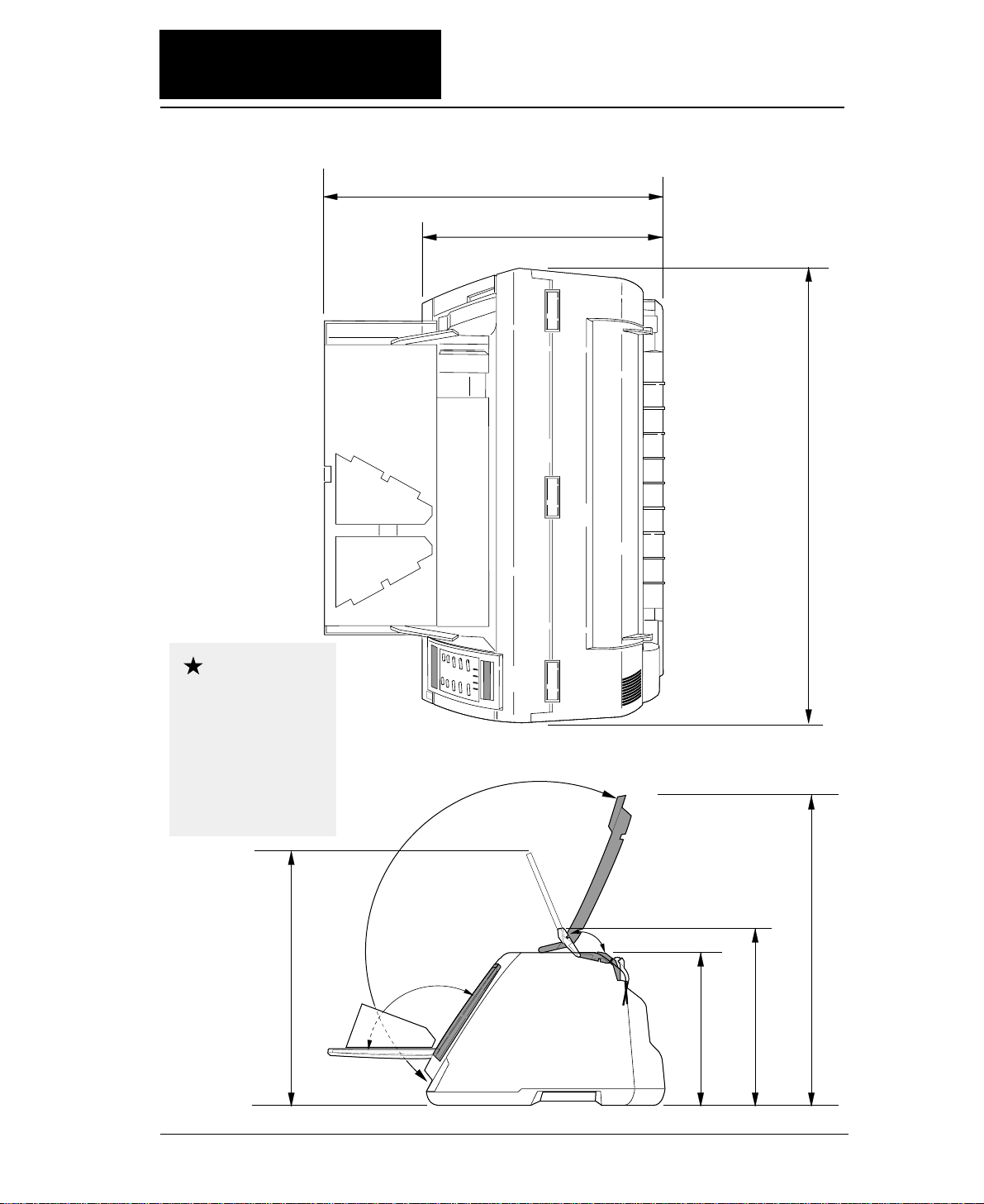
●●
Dimensions
●
The following drawings show the outside dimensions of the printer.
300mm
250mm
520mm 630mm
505mm
395mm
442mm
The weight of the
printer including the
ribbon cassette is
approximately 24 kg
[52.9 lbs.]. Two
persons should carry
the printer.
Caution
Page 18
viii
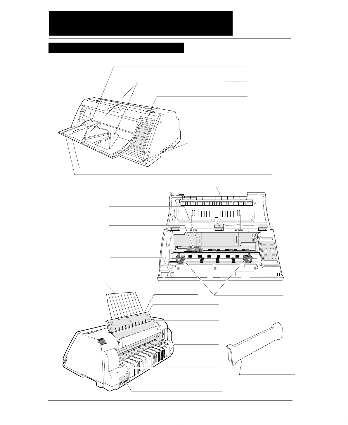
●●
Components and functions
1
1. Paper Guide (for Manual Feeding)
2. Paper Stacker (for Cut Sheet Feeder)
3. Liquid Crystal Display (LCD)
4. Control Panel
11. Power Switch
16. AC Receptacle
17. Serial Connector
18. Parallel Connector
12. Tractor
19. Rear Printer Cover
14. Top Cover
LCD: TOP COVER
5. Paper Rack
LCD: PAPER RACK
15. Rear Cover
LCD: REAR COVER
13. Top Paper Rack
8. Front Cover
LCD: FRONT COVER
10. Print Head
9. Ribbon Cassette
6. Paper Support Guide (for Manual Feeding)
20. Paper Cutter
7. Front Cover Lock Release Button
Appearance of the printer
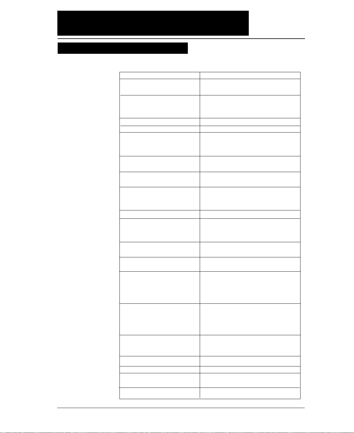
Page 19
ix
The names and functions of the printer components are shown below.
Name (See drawing on left.) Function
1. Paper guide Adjusts the printing position when feeding paper
manually.
2. Paper stacker When the optional CSF is used, sheets of paper
are ejected into this paper stacker. Both sides of
the paper stacker should be set up.
3. Liquid crystal display (LCD) Displays the condition and settings of the printer.
4. Control panel Displays and sets the printer conditions.
5. Paper rack If the “OPEN PAPER RACK” message is
desplayed on the LCD when setting the paper
path, open the paper rack.
6. Paper Support Guide Guide the cut sheet at manuarl feeding.
7. Front Cover Lock release button To open the front cover, push the two buttons
located on the lower corners of the front cover.
8. Front cover To mount fanfold paper on tractors or replace the
ribbon cassette, open the front cover.
9. Ribbon cassette If printed characters vecome pale, replace the
ribbon cassette.
10. Print head Prints characters on paper.
11. Power switch Pressing the power switch toggles the power on
and off.
ON: Switch depressed OFF: Switch released
12. Tractor The tractor pins engage sprocket holes on both
sides of fanfold paper for feeding.
13. Top paper rack Ejected cut sheets are stacked on the top paper
rack.
14. Top cover Eject fanfold paper to the top of the printer. If
the “OPEN TOP COVER” is displayed on the
LCD when setting the paepr path, open the top
cover.
15. Rear cover To eject fanfaold paper to the top of the prieter,
open the rear cover. If the “OPEN REAR
COVER” is displayed on the LCD when setting
the paper path, open the rear cover.
16. AC receptacle
Connect the power to this AC receptacle. The
power is desigated on the rating plate on the back
of the printer.
17. Serial connector
RS-232C interface connector
18. Parallel connector
Parallel interface connector
19. Rear printer cover
When the rear tractor or CSF is used, remove the
rear printer cover.
20. Paper Cutter
Cut the paper after pressing the TEAR OFF key.
●●
Components and functions
Components and functions
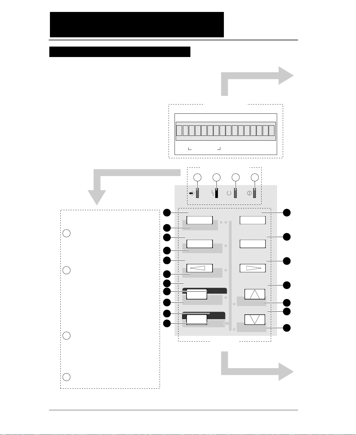
Page 20
x
●●
Components and functions
Control panel explanation 1
DATA ERROR ONLINE POWER
TEAR OFF
ONLINE
PAPER PATH
FORM FEED
LINE FEED
REVERSE LF
TOF SET
QUALITY
EJECT/LOAD
PAPER FORM
RESET
SET UP
MICRO LF
MICRO RLF
EXIT
EXTENDED
ENTER
ALT
FORM
1.5
x
IN OUT
PAPER PATH
F.TR REAR
1
2
3
4
5
6
11
12
13
14
15
16
17
18
7
9
8
10
1 2 3 4
State display Lamps
State display LCD
Key Panel
Blinks while data is transferred.
Lights while data is processed except
during communication or when the
input buffer contains data. Goes out
in other conditions.
ON : Paper is not detected some
other operational error has
occurred.
OFF : Paper is detected.
Blinking : A functional error (such
as home sense error,
internal RAM error,
paper path switching error,
head adjustment error,
park error and skew error)
ON : Printing is enabled.
OFF : Printing is disabled.
Blinking : The cover is open, or
the printer is in the head
temperature protect
condition.
On when printer power is turned on.
State display lamps
1
2
3
4
115
Page 21
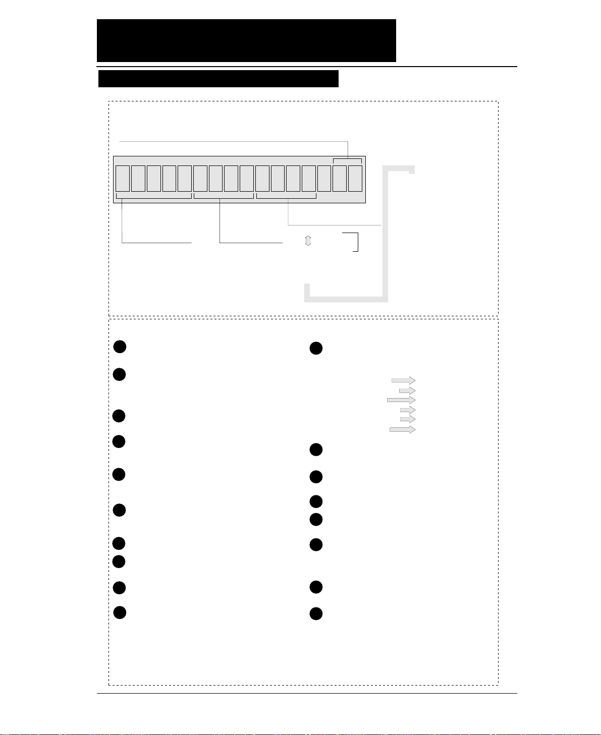
xi
●●
Components and functions
.5x15F . TR REAR1
F. TR
R. TR
MAN
CSF
: Front Tractor
: Rear Tractor
: Manual
: Cut Sheet Feeder
REAR
TOP
FRNT
: Rear
: Top
: Front
1inch=25.4mm
Paper In
Paper Out
15: 15 inches 12: 12 inches 10: 10 inches 5: 5 inches
Paper Width (Fanfold Paper)
2
16.5
A3
A4
A5
Page Length (Fanfold Paper)
Paper Size (Cut Sheet Paper)
: 2 inches
: 16.5 inches
: A3
: A4
: A5
LT
HLT
LG
EX
GLT
GLG
LD
F4
PC
C6
C10
MN
DL
C5
: LETTER
: HALF LETTER
: LEGAL
: EXECUTIVE
: GOVERNMENT LETTER
:
GOVERNMENT LEGAL
: LEDGER
: F4 SIZE
: POST CARD
: COMMERCIAL-6
: COMMERCIAL-10
: MONARCH
: DL Envelope
: C5 Envelope
Feeds the perforation of fanfold paper to the paper
cutter poistion. (For fanfold paper only)
(ALT + TEAR OFF keys)
Press these keys for two seconds or more. Release
the keys when "INITIAL" is displayed on the LCD.
The printer will be reset.
Changes the paper path display. To select the
displayed paper path, press the ENTER key.
(ALT + PAPER PATH keys)
When paper is loaded, the current printing position is
considered as the TOF position.
Loads paper or feed back paper to the parking
position when fanfold paper is used. Loads or
and ejects paper when cut sheet paper is uesd.
(ALT + EJECT/LOAD keys)
Changes the printing quality display. To select
the displayed mode, press the ENTER key.
Enters the SETUP MODE.
Quits the SETUP MODE or EXTENDED
SETUP MODE.
(ALT + SETUP keys)
Enters the EXTENDED SETUP MODE.
Selects an item displayed in the SETUP MODE,
the EXTENDED SETUP MODE, setting the
paper path, setting the paper form or setting the
printing quality.
1
2
3
4
5
6
10
11
12
13
14
15
16
17
7
9
8
When pressing the corresponding key while you
press the ALT key, one of the following
functions is executed.
Changes the printing enable (online) state and
printing disable (offline) state.
Changes the paper form display. To select the
displayed paper form, press the ENTER key.
Feeds one page.
Feeds one line in the forward direction at a pitch
of 1/6 inch.
(ALT + LINE FEED keys)
Feeds one line in the forward direction at a pitch
of 1/360 inch.
(Micro line feed)
Feeds one line in the reverse direction at a pitch
of 1/6 inch.
(ALT + REVERSE LF keys)
Feeds one line in the reverse direction at a pitch
of 1/360 inch.
(Micro reverse line feed)
18
State display LCD
Keys on the panel
LINE FEED
REVERSE LF
SET UP
EJECT/LOAD
PAPER PATH
TEAR OFF
MICRO LF
MICRO RLF
EXTENDED SETUP
QUALITY
TOF SET
RESET
1
Orientation (Cut Sheet Paper)
p: Portrait l: Landscape
Page
Length
Control panel explanation 2
Page 22
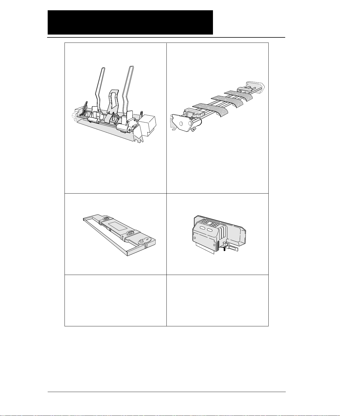
xii
#FB-84008
Cut sheet feeder Rear tractor
For attaching the cut sheet feeder,
see pages 1-22 to 1-26.
For attaching the rear tractor, see pages 1-16 to 1-18.
Print head
#FB-90090
For mounting the print head, refer to the manual
supplied with the print head.
Ribbon cassette
#SBP-1051
For attaching the ribbon cassette,
see pages 1-2 and 1-3.
Current loop interface unit
RS-422A interface unit
#FB-84011#FB-84010
#FB-84009
This unit enables data to be transferred through
an RS-422A interface. This is a built-in unit
that is installed by the dealer. If the RS-422A
interface unit is installed, the RS-232C
interface cannot be used.
This unit converts serial data into 20 mA
current loop signals. This is a built-in unit that
is installed by the dealer. If the current loop
interface unit is installed, the RS-232C
interface cannot be used.
The cut sheet feeder feeds cut sheets automatically
and continuously. A maximum of 150 sheets of
paper (55 kg paper) may be set in the holder of the
cut sheet feeder.
Dual paper parking is available when the rear
tractor is used. Two different types of paper may
be set onto the front and rear tractors and may be
selected by issuing software commands or
pressing the PAPER PATH key to change the
paper paths.
●●
Options and consumables
Page 23
xiii
●●
Maintenance
Periodic maintenance and inspection is recommended to keep
the printer in good condition.
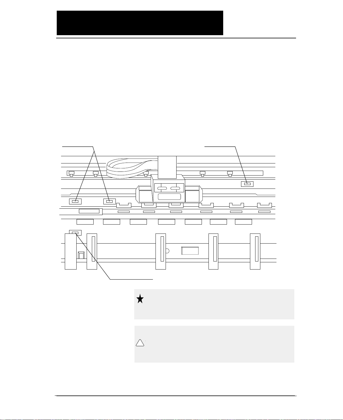
●
Remove paper particles or dust adhered to
the detection sensor cover upper surfaces
(three locations) inside the printer and to the
paper jam sensor surface (one location), by
wiping with a soft clth or a cotton bud. The
paper particles or dust on the sensor
surfaces may cause faulty operation.
Detection sensor Detection sensor
Paper jam sensor
Do not use a hard brush to clean the
sensor cover and the sensor surface.
The brush may scratch the surface.
When opening the front cover just
after the printer has been in operation,
do not touch the printer heard which
is hot and may cause burns.
Caution
!
Caution
Page 24
1-1
—
1. Setting up the printer
—
1. Setting up the printer
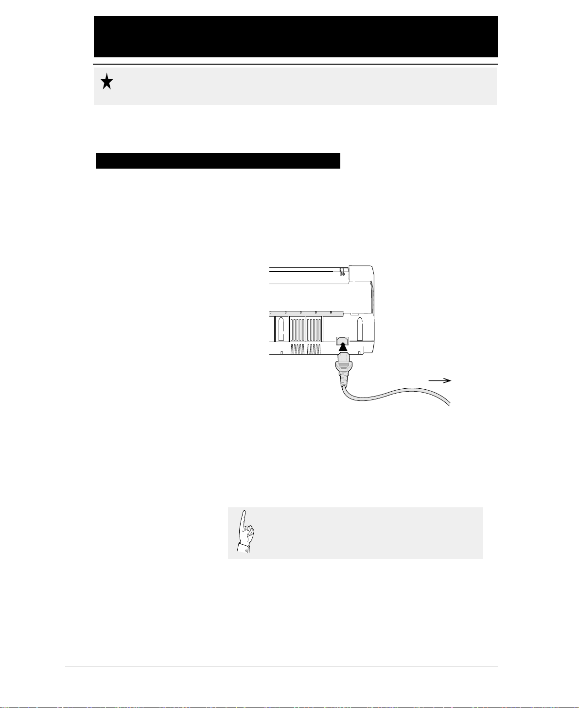
●
Make sure that the power switch is set to off.
Connect the printer with the supplied power
cord to an AC outlet.
●
The AC outlet shall be installed near the
printer and shall be easily accessible.
To AC outlet
Connect the AC power plug to an AC outlet of the voltage
designated on the rating plate on the back of the pirnter.
Once the printer is turned off, wait for three seconds or
more before turning it on again. If the printer is turned
on again within three seconds after turning it off, it
may malfunction due to an initializtion failure.
●●
Connecting the printer to Power
Caution
Page 25
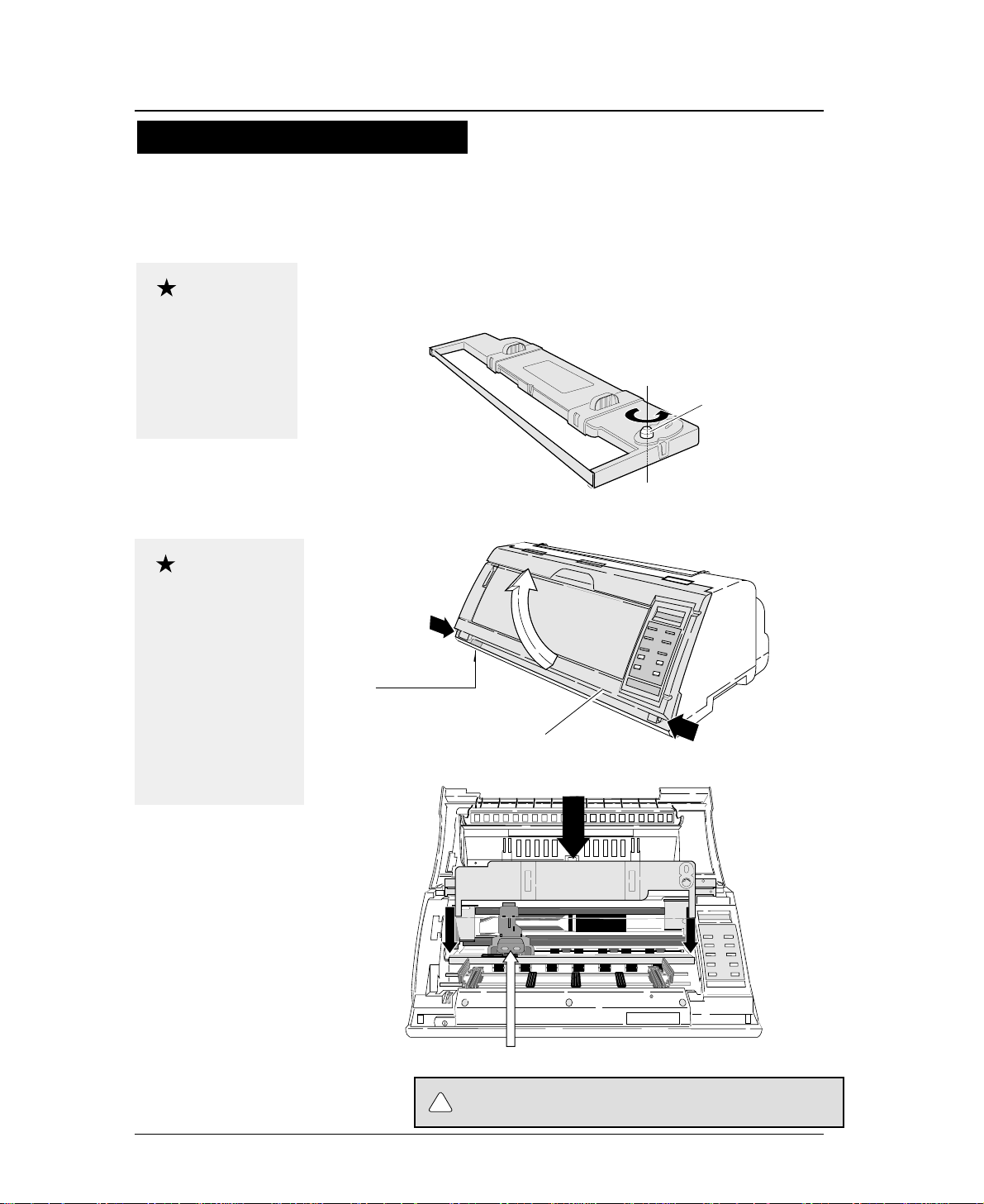
1. Turn the ribbon feed knob on the ribbon
cassette counterclockwise to stretch the
ribbon tight.
2. Turn off the power. Open the front cover.
3. Attach the ribbon cassette as shown below.
1-2
Do not touch the print head immediately
after printing becouse it is too hot.
Use the specified
ribbon cassette .
When power is turned
off, data in the buffer
is lost. Output all data
before turning off the
printer.
Open the front cover by
pressing both side locks
with both hands. Hold
both sides with both
hands to raise it upward
slowly. When closing
the front cover, hold
both sides with both
hands to pull it down
slowly. Press the front
cover to lock it.
Stretch the ribbon
Ribbon feed knob
Installing the ribbon cassette
Approximately 15 seconds after the printer is rutned on, the print head will move to
the left.
Print head position
Front cover
Power switch
Every press of the power
switch turns the power on
or off.
—
1. Setting up the printer
—
●
Installing the ribbon cassette
Caution
Caution
!
CAUTION
Page 26
1-3
●
Installing the ribbon cassette
—
1. Setting up the printer
—
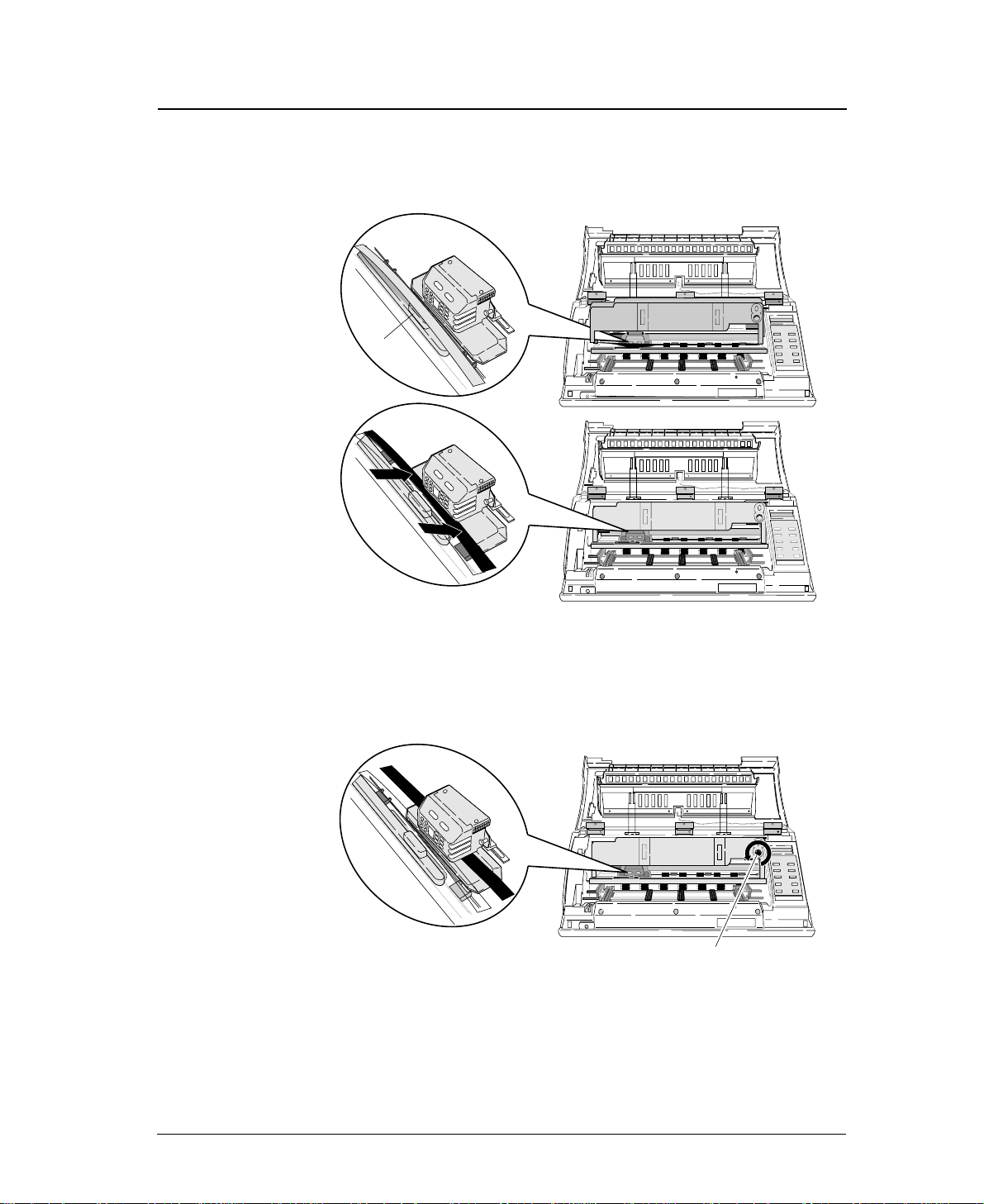
4. Slide the ribbon toward the print head so
that the ribbon is lightly in contact with the
projection of the print head.
5. Attach the cassette firmly to the mounting
plate. Turn the ribbon feed knob
counterclockwise.
Fit the right and left projections on the mounting plate to the holes in
the bottom of the ribbon cassette.
6. Close the front cover.
Pull down the front cover slowly toward you with both hands from
both sides to close it.
Push down on both sides at the bottom of the front cover to close it
firmy. Two hands are required to engage and lockthe front cover on
both sides.
Slide
Slide
Projection
Ribbon feed knob
Page 27
1-4
—
1. Setting up the printer
—
●
Paper path
1
2
Paper loading direction
Rear tractor
(Optional)
Paper loading
direction
3
Paper rack
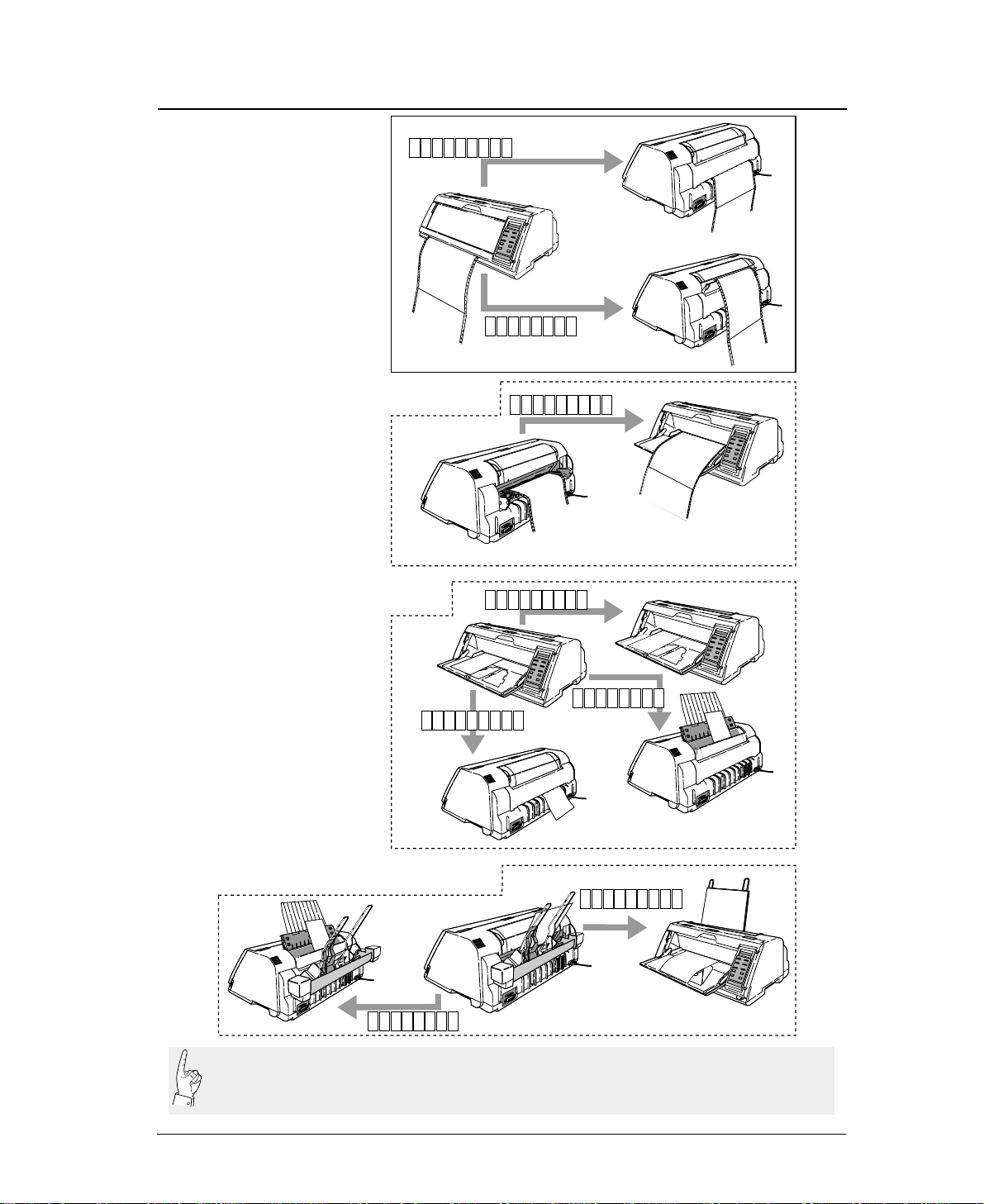
2. Front loading, top ejection
This paper path applies a smaller load to the paper.
This is recommended for printing on thick paper
(such as multipart paper or label sheets).
1. Front loading, rear ejection
This paper path is recommended if fanfold paper is
cut along the perforation frequently.
The perforation is automatically fed to the paper
cutter of the top cover by pressing the TEAR OFF
key so that the paper may be torn off easily.
To cut the paper, hold the upper cover firmly with
one hand and tear the paper towards you.
3. Rear loading, front ejection
Dual paper parking is available when the optional
rear tractor is used. Two types of fanfold paper of
different size and thickness may be used and
selected from the control panel or by issuing a
software command (ESC EM or software setup*)
from the computer.
* Software setup commands
The software setup commands are unique to this
printer. Most functions available on the SETUP
MODE and EXTENDED SETUP MODE can may
11x 5F.TR REAR
11x 5FTRTOP
11x 5R.TR FR T N
Liquid crystal display
Inside of the printer viewed
from the right.
✩
Inside of the printer viewed
from the right.
✩
.
1
1
1
Path of fanfold paper
The three fanfold paper paths shown below are available. For selecting a paper
path, See pages 1-6 and 1-7.
Rear tractor (Option)
Front tractor
Page 28
1-5
—
1. Setting up the printer
—
●
Paper path
Path of cut sheet paper
The five cut sheet paper paths shown below are available.
1. Front loading, front ejection
This paper path applies a lighter load on feeding paper. This
is recommended for printing on thick paper (such as
multipart paper, postcards, and envelopes).
3. Front loading, top ejection
This paper path enables face-down stacking.
1
3
2
Paper loading
direction
4. CSF loading, front ejection
This paper path is suitable for thick paper (such as multipart
paper, postcards and so on). Sheets of paper are stacked face-up.
5. CSF loading, top ejection
This paper path enables face-down stacking.
Paper loading
direction
4
5
A4 pMAN F RN T
A4 pMAN REAR
A4 pMAN TOP
A4 pCSF FR
A4 pCSF TOP
Inside of the printer
viewed from the right.
✩
✩
This paper path applies a lighter load on feeding paper. It is
recommended for printing on thick paper (such as multipart
paper, postcards, and envelopes).
NT
2. Front loading, rear ejection
Inside of the printer
viewed from the right.
Manual paper feeding
Cut sheet paper (Option)
●Sheets of paper are loaded manually one at a time.
Page 29

1-6
—
1. Setting up the printer
—
●
Selecting the Paper path
1. Press the PAPER PATH key.
The paper path currently selected is displayed.
2. Continue to press the PAPER PARH key until
“PATH: F. TR. -> TOP ” is displayed. Press
the ENTER key.
Selecting the paper path
The following shows an example of changing the paper path for reference. The
example shown below changes front tractor loading and rear ejection to the front
tractor loading and top ejection.
11x 5
F .
TR EA
IN
OUT
FORM
PAPER PATH
>
RE
T
F
-APH
.T
RA
PAPER PATH
R
.:
1RR
PAPER PATH
ENTER
IN
OUT
PAPER PATH
FORM
11x 5F.RT
IN
OUT
PAPER PATH
FORM
IN
OUT
PAPER PATH
FORM
1
MEM 1F
. R->R ATERO
MEM 1F
. R->T PTO
->T PO
O
Page 30
1-7
—
1. Setting up the printer
—
●
Selecting the paper path
1
1
AAAAAAAAAAAAAAAA
AAAAAAAAAAAAAAAA
AAAAAAAAAAA
AAAAAAAAAAAAAAAA
AAAAAAAAAAAAAAAA
AAAAAAAAAAAAAAAA
AAAAAAAAAAAAAAAA
AAAAAAAAAA
AAAAAAAAAAAAAAAA
AAAAAAAAAAAA
AAAAAAAAAAAAAAAA
AAAAAAAAAAAAAAAA
AAAAAAAAAAAAAAAA
1
1
aaaaaaaaaaaaaaaaa
aaaaaaaaaaaaaaaaa
aaaaaaaaaaaaaaaaa
aaaaaaaaaaaaaaaaa
aaaaaaaaaaaaaaaaa
aaaaaaaaaaaaaaaaa
aaaaaaaaaaaaaaaaa
◆Cut sheet paper (Manual feeding)
◆Fanfold paper
1
1
◆Cut sheet paper (Optional cut sheet feeder)
1
◆Fanfold paper (Optional rear tractor)
LOAD
EJECTION
LOAD
EJEC-
TI
ON
EJEC-
TIO
N
LOAD
EJECTION
EJECTION
EJECTION
LOAD
EJECTION
EJEC TION
F.TR REA
F.TR TOP
R.TR FRN
MAN F RN
MAN R EA
MAN TOP
CSF TOP
CSF FRN
EJEC-
TION
R
T
T
R
T
AAAAAAAAAAAA
AAAAAAAAAAAAAAAA
AAAAAAAAAAAA
AAAAAAAAAAAAAAAA
AAAAAAAAAAAA
AAAAAAAAAAAAAAAA
AAAAAAAAAAAA
AAAAAAAAAAAAAAAA
The optional CSF and rear tractor cannot be used together. If the optional CSF or rear tractor is
installed, enable it by using the EXTENDED SETUP MODE (#60 option). If the option is not
enabled on the EXTENDED SETUP MODE, the paper path cannot be selected.
Page 31

1-8
—
1. Setting up the printer
—
●
Paper
16 mm or more
0/60 inch - 63/60 inches
(#3 TOF ADJUSTMENT on SETUP
MODE)
2 mm
Printing area
Printing area
5, 10, 15 inches
(#5 PAPER WIDTH on SETUP MODE)
Perforation
2.5 - 16.5 Inches
(#4 PAGE LENGTH on SETUP MODE)
0/6 inch - 15/6 inches
(#6 TOP MARGIN on SETUP
MODE)
0/6 inch - 15/6 inches
(#7 BOTTOM MARGIN on
SETUP MODE)
Last page
Paper form
Multipart
form
Rear tractor 3 ~ 16.5 inches (76 ~ 420mm)
1
9 or less
1
0.08
~ 0.12mm
55 ~ 90kg 34kg x 9P
0.12
~ 0.59mm
0.12
~ 0.18mm
125kg or less
Front tractor 3 ~ 16 inches (76 ~ 406mm)
Paper width
Number of sheets
Thickness
Paper weight
16 mm or more
Label
form
Single
Paper quality Wood-free paper
22 holes
Page length
0.5 inch × 22 = 11 inches
0.5 inch
30 holes
Page width
0.5 inch × 30 = 15 inches
Page length
Paper width
Sprocket holes are made on both sides
of fanfold paper at an interval of 0.5
inch, which can be used to calculate
the page length and width.
The page length can be determined by
multiplying the number of sprocket
holes per page by 0.5 inch.
To find the paper width, use another
sheet of fanfold paper and count the
number of sprocket holes.
Printing area on fanfold paper
Calculating sizes of fanfold paper
Sizes of fanfold paper are
generally shown in inches.
One inch is 25.4 mm.
When fanfold paper is used, set the page length (#4 PAGE LENGTH) and paper
width (#5 PAPER WIDTH) on the SETUP MODE. For setting, see page 1-12.
Page 32

1-9
A4, LETTER, LEGAL, A3, etc
(#4 PAGE LENGTH on SETUP MODE)
0/60 inch - 63/60 inches
(#3 TOF ADJUSTMENT on SETUP
MODE)
4mm
Printing area
2 mm or more2 mm or more
Horizontally loaded
size A5 sheets and
postcards cannot be
ejected upward.
Standard-size form
Multipart paper
Glued portion
Approx. 0.5 mm
The thickness of the bound
portion is the sum of the
paper thickness and 0.25 mm
or less.
Use wood-free paper. Cut sheet paper can be
loaded manually or by using the CSF.
Paper form
Paper quality
Number of sheets
Thickness (mm)
Paper weight
Single
0.08 ~ 0.12
55 ~ 90kg 34kg x 9P
0.12 ~ 0.59 0.08 ~ 0.8
0.5 or less
Wood-free
paper
Wood-free paper
0.08 ~ 0.11
55 ~ 78Kg 34kg x 6P
0.12 ~ 0.39 0.08 ~ 0.22
Manual paper feeding CSF paper feeing
Available standards-size forms
Envelopes and horizontally set post cards
cannot be printed by using the CSF.
Non-carbon, middle carbon
and back carbon multipart
paper can be used.
Multipart
form
1
9 or less
11
Card Envelope
Carbon or
non-carbon
Paper form
Paper quality
Number of sheets
Thickness (mm)
Paper weight
Paper length
Single
Wood-free
paper
1
Multipart
form
6 or less
Non-carbon
140mm and over
Card
Wood-free
paper
1
39 ~ 78kg 55 ~ 165kg
Paper Size
Manual Feeding CSF Feeding
A3
A4
A5
Letter
Half Letter
Legal
Executive
Government Legal
Government Letter
Ledger
F4
Post card
Commercial -6
Commercial -10
Monarch
DL
C5
Portrait Landscape Landscape
(297mm X 420mm)
(210mm X 297mm)
(148mm X 210mm)
(8.5" X 11")
(5.5" X 8.5")
(8.5" X 14")
(7.25" X 10.5")
(8.5" X 13")
(8" X 10.5")
(11" X 17")
(210mm X 330mm)
(100mm X 148mm)
(6 1/2" X 3 5/8")
(9 1/2" X 4 1/8")
(3 7/8" X 7 1/2")
(110mm X 220mm)
(162mm X 229mm)
❈1 Paper length 150mm (5.9inch) or less can not be ejected to the top.
❈2 A3 (portrait) or Ledger (portrait) can not be stacked on the top paper rack.
Regular size formEnvelope
Portrait
—
1. Setting up the printer
—
●
Paper
Printing area on cut sheet paper
Specify the paper size of cut sheet paper using #4 PAGE
LENGTH on the SETUP MODE. For setting, see page 1-19.
Page 33

1-10
—
1. Setting up the printer
—
●
Selecting the paper form
Paper form selection 1
15
12:
10:
5:
15 inches
12 inches
10 inches
5 inches
Paper Width
(Fanfold Paper)
2
16.5
A3
A4
A5
LT
HLT
LG
LD
EX
: 2 inches
: 16.5 inches
: A3
: A4
: A5
: LETTER
: HALF LETTER
: LEGAL
: LEDGER
: EXECUTIVE
Page Length (Fanfold Paper)
Paper Size (Cut Sheet Paper)
GLT
GLG
F4
PC
C6
C10
MN
DL
C5
: GOVERNMENT LETTER
: GOVERNMENT LEGAL
: F4 SIZE
: POST CARD
: COMMERCIAL-6
: COMMERCIAL-10
: MONARCH
: DL Envelop
: C5 Envelop
F
1.5x 5
.TR
REAR
1
p:l:Portrait
Landscape
Orientation
(Cut Sheet Paper)
Page
Length
1
11x 5F.TR REAR
IN
OUT
FORM
PAPER PATH
PAPER FORM
4Ap4
PAPER FORM
PAPER FORM
PAPER FORM
PAPER FORM
PAPER FORM
PAPER FORM
PAPER FORM
111 I x 15
IN
1
211 I x 15
NIN
311 I x 15
IN
5Ap4
6Ap4
N
N
Factory default setting
Liquid crystal display
If the EEPROM is
initialized, preset form
sizes are replaced by the
factory default settings.
Sizes of up to six frequently-used forms may be stored in MEMO 1 to MEMO 6 in the internal memory.
Any of the stored sizes may be read out of the memory with the PAPER FORM key whenever necessary.
See page 1-31.
Page 34

1-11
—
1. Setting up the printer
—
1. Press the PAPER FORM key.
The paper size currently selected is displayed.
2. Continue to press the PAPER FORM key to
select MEMO 3 as shown below.
3. Specify the intended form size as shown
below.
4. The A5 portrait form is set in MEMO 3.
●
Selecting the paper form
Paper form selection 2
The following shows an example of setting form size for reference. The example below
shows how to change the size stored in MEMO 3 ( page length: 11 inches, paper width:
15 inches) to an A5 portrait form.
Specifying form size
11 5xF.TR RE
I
IN
OUT
PAPER FORM
PAPER PATH
IN
OUT
PAPER PATH
PAPER FORM
PAPER FORM
N1xIA1R11
N
51
SET UP
F.TR REAR 11 x 15
1. MULTIPART
4. PAGE LENGTH
SIZE: A5 p
PAGE:11 INCH
1. MULTIPART
SIZE: A5 p*
ENTER
SIZE: A5 p
EXIT
SAVE?: YES
ENTER
SAVE?: YES
F.TR REAR A5 p
4. PAGE LENGTH
4. PAGE LENGTH
PAPER PATH
ENTER
IN
OUT
PAPER PATH
FORM
11x 5F.RT
IN
OUT
PAPER PATH
FORM
IN
OUT
PAPER PATH
FORM
1
MEM 1F
. R->R ATERO
MEM 1F
. R->T PTO
->T PO
O
Page 35

1-12
1. Check the rating of the fanfold paper to be
used that is marked on the side of the
package.
2. Press the PAPER PATH key to select the
desired paper path.
—
1. Setting up the printer
—
●
Loading fanfold paper (Front tractor)
Fanfold paper setting procedures 1
This section describes how to set fanfold paper for front loading and rear ejection
or front loading and top ejection. Before setting fanfold paper, it is necessary to
specify the page length, paper width, etc. on the SETUP MODE.
Rating
10 X 11 - 1P
Page lengthPaper width
Fanfold paper rating marked on side of package (Example)
Multipart paper
(Number of sheets)
Paper loading direction
Paper loading direction
F.TR REAR 11 x 15 F.TR TOP 11 x 15
1
1
Page 36

3. Specify the page length using #4 PAGE
LENGTH on the SETUP MODE as shown
below.
4. Then specify the paepr width using #5
PAPER WIDTH on the SETUP MODE as
shown below.
1-13
—
1. Setting up the printer
—
●
Loading fanfold paper (Front tractor)
Fanfold paper setting procedures 2
SET UP
1. MULTIPART
4. PAGE LENGTH
1. MULTIPART
ENTER
4. PAGE LENGTH
F.TR REAR A5 p
PAGE: 11 INCH
SIZE: A5 p*
PAGE: 11 INCH
PAGE: 11 INCH*
4.PAGE LENGTH
ENTER
5.PAPER WIDTH
SAVE?: YES
F.TR REAR 11 x 10
WIDTH: 10 INCH
WIDTH: 15 INCH*
WIDTH: 10 INCH*
ENTER
WIDTH: 10 INCH
EXIT
SAVE?: YES
5.PAPER WIDTH
Page 37

1-14
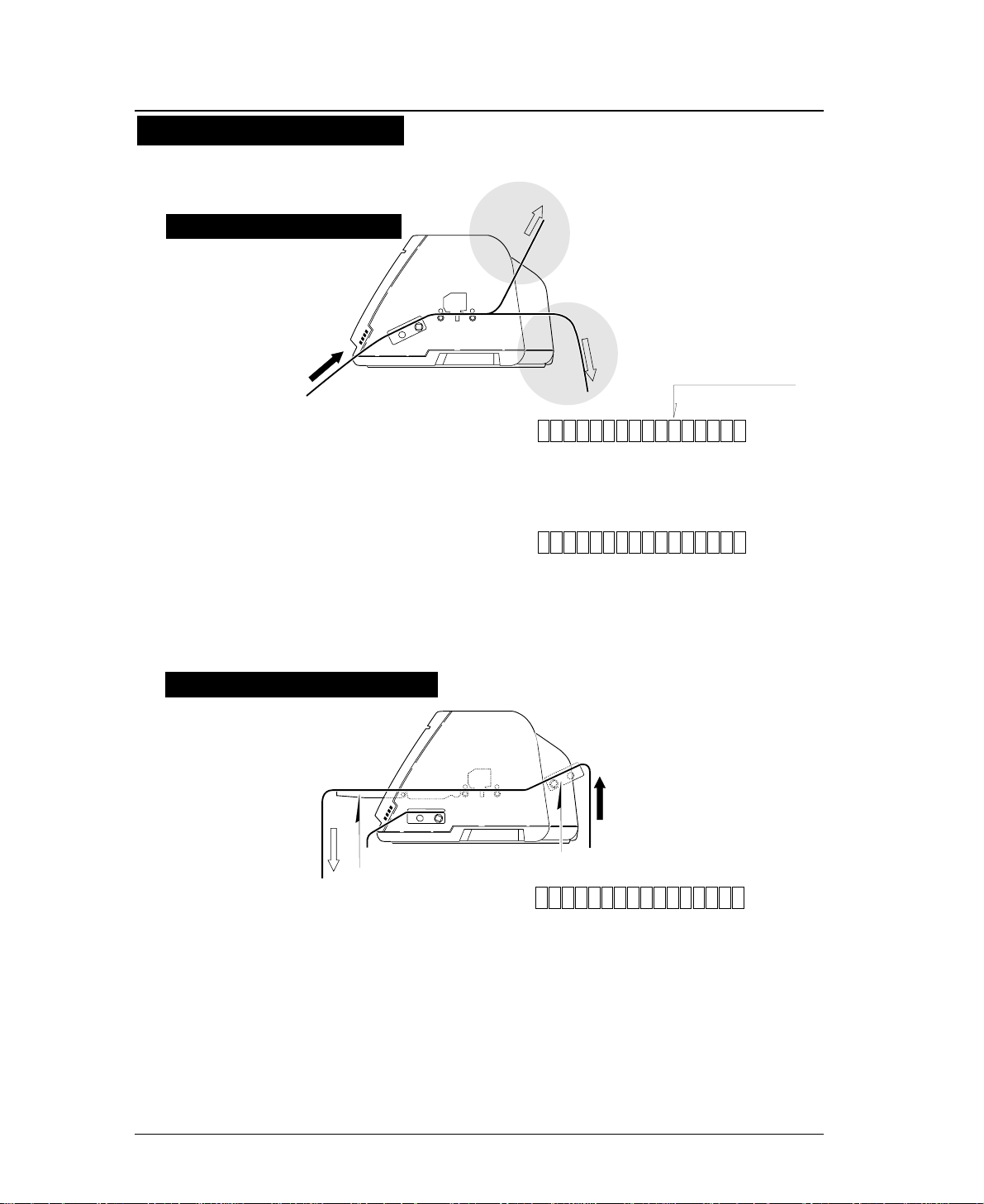
5. Open the front cover.
6. Lift to release the tractor lock lever. Move
the left tractor to the triangle mark. Then
push down on the lever.
—
1. Setting up the printer
—
●
Loading fanfold paper (Front tractor)
Fanfold paper setting procedures 3
Do not put your finger under the tractor cover.
Open the front cover by
pressing both side locks
with both hands. Hold
both sides with both
hands to raise it upward
slowly. When closing
the front cover, hold
both sides with both
hands to pull it down
slowly. Press the front
cover to lock it.
Push the lock levers of
both tractors to the
LOCK positions firmly.
If the lock levers
protrude from the
tractor covers, paper
will not be fed properly,
resulting in paper
jamming.
In order to load
less than 5 inch
width fanfold
paper, remove one
or two tractor
guides.
Caution
Caution
Release
Lock
Release
!
CAUTION
Tractor guide
Triangle mark
Lock
Lock lever
Page 38

1-15
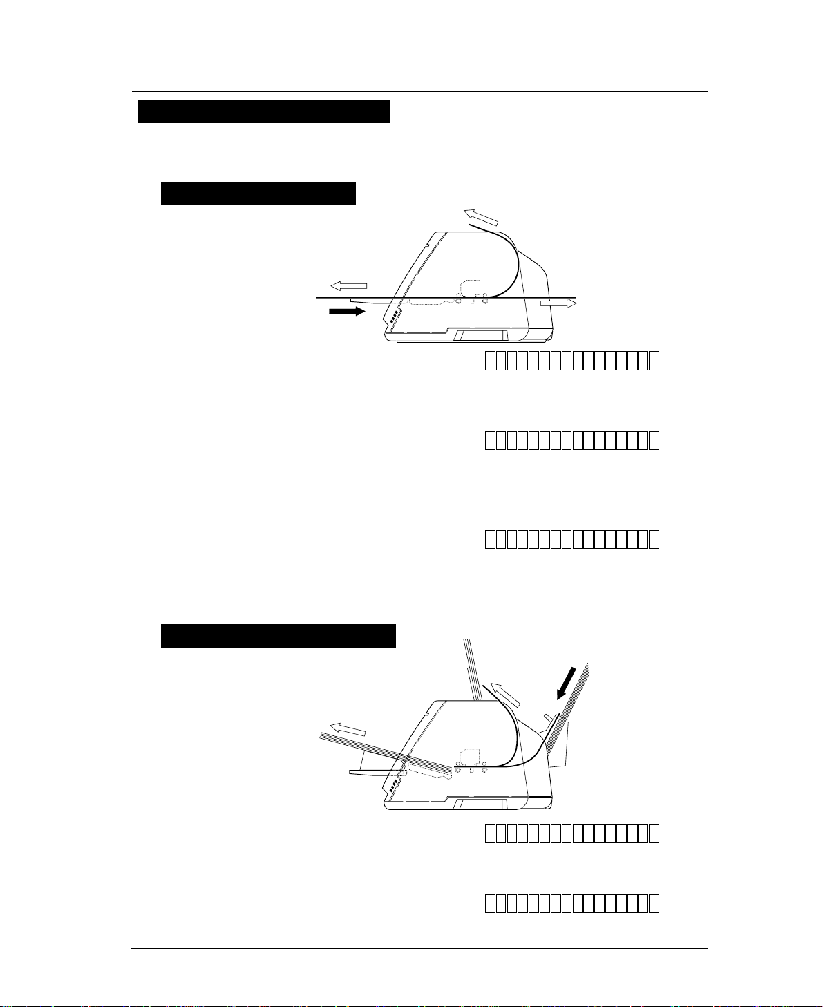
7. Open the tractor covers on both sides. Fit
the sprocket holes on both sides of the
fanfold paper to the tractor pins. Then close
the tractor covers. Push down the lock lever
of the right tractor.
8. Close the front cover.
Hold both sides of the front cover with both
hands and pull down the front cover slowly.
Press the front cover to lock it.
—
1. Setting up the printer
—
●
Loading fanfold paper (Front tractor)
Fanfold paper setting procedures 4
By default, paper is
fed to the 14/60
inch (approximately
6 mm) position
from the top. This position
may be freely adjusted on
the SETUP MODE
between 0/60 inch (0 mm)
and 63/60 inches
(approximately 26.7 mm)
from the top of paper or the
perforation at a pitch of
1/60 inch.
The TOF position can be set from 0/60 inch (0
mm). However, if this position is set to 0/60 to
9/60 inch, paper may jam, depending on the paper condition. Normally,
it is recommended that the TOF position be adjusted to the 14/60 inch
(approximately 6 mm) position from the top of the paper.
when setting the paper on the tracter, Take care
not to over tighten or allow too much slack. Over
tightening deforms the guide holes and the paper may become
disconnected from the tracter during printing. Too much slack may
cause the paper to become clogged when it is inserted.
Caution
Caution
Page 39

1-16
—
1. Setting up the printer
—
●
Loading fanfold paper (Rear tractor)
1. Detach the rear printer cover from the
printer.
2. Install the rear tractor, and plug in the
connector.
Dual paper parking is available if the optional rear tractor is used. This funcion
enables two types of fanfold paper of different formats to be set together and
selected with the PAPER PATH key on the printer or by issuing a setup command
from the computer.
1
Leg
Leg
1
Paper setting procedures usig rear tarctor 1
Pull the upper
part of the rear
printer cover to
the front to
detach it from the printer.
When attaching the rear
printer cover, insert
the two legs into the
printer and then press
the rear printer cover
to lock it.
Page 40

1-17
—
1. Setting up the printer
—
3. Adjust the tractor guides so that they are
located at almost the same interval. Lift and
release the tractor lock levers. Move the left
tractor to the triangle mark, then push down
the lever.
4. Set fanfold paper onto the rear tractor. Push
down the lock lever of the right rear tractor.
●
Loading fanfold paper (Rear tractor)
Triangle mark
1
Tractor guide
Lock
Release
1
Paper setting procedures usig rear tarctor 2
Push the lock levers of
both tractors to the
LOCK positions firmly.
Do not put your
finger under the
tractor cover.
In order to load
less than 8 inch
width fanfold
paper, remove
one or two tractor
guides.
Caution
!
CAUTION
Page 41

1-18
5. Enter the EXTENDED SETUP MODE. Select
the rear tractor on this menu so that the
printer recognizes that the rear tractor is in
use.
6. Press the PAPER PATH key to select REAR
Tr FRONT.
7. “OPEN PAPER RACK” will be displayed. Open
the paper rack.
—
1. Setting up the printer
—
●
Loading fanfold paper (Rear tractor)
SET UP
F.TR REAR 11 x 10
20. EMULATION
60. OPTION
NOT INSTALL*
60. OPTION
ENTER
EXIT
F.TR REAR 11 x 10
ALT
60. OPTION
INITIAL
INITIAL
OPTION: REAR Tr.*
OPTION: REAR Tr.
OPTION: REAR Tr.
Paper setting procedures usig rear tarctor 3
Page 42

1. Check the rating of the cut sheet paper to be
used that is marked on the side of the
package.
2. Press the PAPER PAHTH key to select
MANUAL FRONT or MANUAL TOP, or MANUAL
REAR .
3. Specify the form size correctly on the
SETUP MODE (#4 PAGE LENGTH).
1-19
—
1. Setting up the printer
—
●
Loading cut paper
(manual paper feeding)
Select Manual feeding procedures 1
This section describes how to load cut sheet paper, showing an example of using
an A5 portrait form. Before loading a cut sheet, it is necessary to specify the
paper size on the SETUP MODE. Be sure to load cut sheet paper one sheet at a
Rating
A5 (Wood-Free / 70kg)
Wood-free paper
Form size
Cut sheet paper rating marked on side of
package (Example)
Paper weight
1. MULTIPART
4. PAGE LENGTH
SIZE: A5 p
SIZE: A4 p*
4. PAGE LENGTH
SIZE: A5 p *
ENTER
SIZE: A5 p
ENTER
SET UP
MAN FRNT A4 p
1. MULTIPART
SAVE? : YES*
EXIT
4. PAGE LENGTHSAVE? : YES
MAN FRNT A5 p
Page 43

1-20
4. Adjust the edge of the paper guide to
approximately 2 mm left of the triangle mark.
Refer to page 1-21 regarding use of the paper rack guide.
●
Loading cut paper
(manual paper feeding)
—
1. Setting up the printer
—
Select Manual feeding procedures 2
Mark
AAAAAAAAAAAAAAAA
AAAAAAAAAAAAAAAA
AAAAAAAAAAA
AAAAAAAAAAAAAAAA
AAAAAAAAAAAAAAAA
AAAAAAAAAAAAAAAA
AAAAAAAAAAAAAAAA
AAAAAAAAAA
AAAAAAAAAAAAAAAA
AAAAAAAAAAAA
AAAAAAAAAAAAAAAA
AAAAAAAAAAAAAAAA
AAAAAAAAAAAAAAAA
1
aaaaaaaaaaaaaaaaa
aaaaaaaaaaaaaaaaa
aaaaaaaaaaaaaaaaa
aaaaaaaaaaaaaaaaa
aaaaaaaaaaaaaaaaa
aaaaaaaaaaaaaaaaa
aaaaaaaaaaaaaaaaa
LOAD
EJECTION
EJEC TION
MAN F
MAN
REA
TOP
1
EJECTION
R
RN
T
MAN
The triangle mark shows the printing start
position at the left of the printer.
Page 44

1-21
5. Insert a sheet of paper straight along the
paper guide.
If paper is inserted at a skewed angle, the skew sensor detects
and the paper is ejected.
—
1. Setting up the printer
—
●
Loading cut paper
(manual paper feeding)
Insert sheets of paper one at a time along the paper
guide. Only one sheet at a time can be set on the
paper rack.
Select Manual feeding procedures 3
To alternate manual printing and printing with the
optional rear tractor or CSF, be sure to move the
paper guide to the left end after completion of
manual printing. Further, return the paper guide of the paper rack
to the left end. If printing is performed using the rear tractor or
CSF with the paper guide left in the manual feeding position,
paper loaded form the back will hit the paper guide, resulting in
paper jamming.
Move the Paper Guide and the Paper Support Guide to the left end.
When using wide paper, insert
the paper using the paper
support guide attached to the
left end of the paper rack.
Caution
Caution
Page 45

1-22
1. Press the EJECT/LOAD key to move back
the fanfold paper.
2. Enter the EXTENDED SETUP MODE
according to the proceures shown below
and select #60 OPTION on the menu. Select
CSF (cut sheet feeder).
3. Detach the rear printer cover from the
printer.
—
1. Setting up the printer
—
●
Printing using the cut sheet feeder (Option)
Printing procedures using CSF 1
An optional cut sheet feeder is available for this printer. The cut sheet feeder is
useful for continuous printing on cut sheets.
The paper holder of the cut sheet feeder accommodates a maximum of 150 sheets
(of 55 kg paper). Normal paper and multipart paper can be used.
SET UP
F.TR REAR 11 x 10
20. EMULATION
60. OPTION
OPTION: CSF
NOT INSTALL*
60. OPTION
OPTION: CSF*
ENTER
EXIT
F.TR REAR 11 x 10
ALT
60. OPTION
INITIAL
INITIAL
OPTION: CSF
1
Leg
Leg
Pull the upper
part of the rear
printer cover to
the front to
detach it from the printer.
When attaching the rear
printer cover, insert the
two legs into the printer
and then press the rear
printer cover to lock it.
Page 46

1-23
4. Attach the hoppers and center support to
the cut sheet feeder.
5. Attach the cut sheet feeder to the back of
the printer.
—
1. Setting up the printer
—
●
Printing using the cut sheet feeder (Option)
Printing procedures using CSF 2
1
CSF
1
Hopper
Center support
Use two hands and hold
firmly at each end when
lifting the cut sheet
feeder. Personal injury
can occur if the CSF unit
is dropped.
!
CAUTION
Page 47

1-24
6. Shuffle the paper as show below.
7. Turn the CSF release levers to the front to
release the paper bins.
—
1. Setting up the printer
—
●
Printing using the cut sheet feeder (Option)
Printing procedures using CSF 3
Be sure to shuffle sheets sufficiently before setting
them. Otherwise, several sheets of paper may be fed
at the same time resulting in a paper jam.
CSF release lever
Caution
Page 48

1-25
8. Turn the paper guide lock levers to the
RELEASE positions to adjust the paper
width.
9. Turn the paper guide lock levers to the
LOCK positions.
—
1. Setting up the printer
—
●
Printing using the cut sheet feeder (Option)
1
Mark
Adjust the edge of the paper guide to
appriximately 2mm left (outside) of the
triangle mark.
CARD
Paper guide lock lever
Postcard changeover lever
When printing on postcards,
turn this lever down.
Release
Lock
Printing procedures using CSF 4
The triangle mark shows the printing start
position at the left of the paper.
Adjust the paper guide
to remove the gap
between the paper and
the paper guide, ensuring
that the paper does not press
too tightly against the paper
guide to avoide faulty
feeding.
Page 49

1-26
—
1. Setting up the printer
—
●
Printing using the cut sheet feeder (Option)
10. Move the CSF release levers to the back to
fix the paper bins.
11. Press the PAPER PATH key to select CSF
FRONT or CSF TOP.
12. Press the ENTER key to select the displayed
paper path.
CSF TOP A4 p
CSF FRNT A4 p
Printing procedures using CSF 5
Page 50

1-27
—
1. Setting up the printer
—
1. Turn on the printer power while keeping the
LINE FEED key, or LINE FEED and ONLINE
keys depressed.
After initialization, the printer enters the self-test mode and starts the
self-test.
During printing, the ONLINE lamp blinks at an interval of 0.5 second.
The following message is displayed on the LCD.
The draft or LQ self-test prints the ASCII character in a rolling pattern.
2. To pause the self-test, press the ONLINE
key.
To terminate the self-test, keep the ALT and
RESET keys depressed for two seconds or
more, or turn the power switch to off.
●
Running self-test
It is recommended that a self-test of the printer be performed before connecting
the printer to the computer. The printer can execute the self-test by itself to check
on printing quality, printing pressure, and any printer troubles.
Draft self-test printing: Turn on power while pressing the
LINE FEED key.
LQ self-test printing: Turn on power while pressing the LINE
FEED and ONLINE keys.
Draft self-test printing “SELF TEST DRAFT”
LQ self-test printing “SELF TEST LQ”
Page 51

1-28
—
1. Setting up the printer
—
1. Make sure that the power switch is turned to
off. Connect the signal cable to the printer
and computer.
2. Specify the following parallel interface
parameters on the EXTENDED SETUP
MODE.
●
Connecting the printer to the computer
13
25
1
14
Close the latches to secure
the connector.
Latches
Parallel Interface
The printer has a Centronics parallel interface and an RS-232S serial interface
as standard features.
Select the appropriate interface according to the computer and application
software to be used.
Connecting the priter to the computer
The printer has been set to the normal parallel
interface setting before shipment. If the default
setting does not provide proper communication,
recheck the interface setting shown below.
EXTENDED SETUP MODE Default setting page
#70. INTERFACE Parallel 3-46
#71. SELECT IN ENABLE 0 3-47
#81. BUFFER SIZE 512 KB 3-52
#82. BUSY/ACK TIMING TYPE 2 3-53
#83. DATA LATCH TIMING TYPE F. 3-53
#84. ERROR STATUS YES 3-54
Page 52

1-29
—
1. Setting up the printer
—
1. Make sure that the power switch is turned to
off. Connect the signal cable to the printer
and computer.
2. Specify the following serial interface
parameters on the EXTENDED SETUP
MODE.
●
Connecting the printer to the computer
Serial Interface
13
25
1
14
Tighten the screws on both
sides of the connector.
Specify the following serial interface parameters on
the EXTENDED SETUP MODE.
EXTENDED SETUP MODE Default setting Page
#70. INTERFACE Parallel 3-46
#
71. SELECT IN ENABLE 0
3-47
#
72. PARITY BIT Non
3-47
#
73. DATA LENGTH 8 bits
3-48
#
74. STOP BIT 1 bit
3-48
#
75. PROTOCOL DTR
3-49
#
76. BAUD RATE 9600 bps
3-49
#
77. SERIAL ERROR Print
3-50
#
78. CTS ENABLE No
3-50
#
79. CD ENABLE No
3-51
#
80. DSR ENABLE No
3-51
#81. BUFFER SIZE 512 KB 3-52
Page 53

1-30
—
1. Setting up the printer
—
1. Turn on the printer power while keeping the
FORM FEED key or FORM FEED and ONLINE
keys depressed.
While printing the hexadecimal dump list, the following message is
displayed.
2. Output data from the computer to the
printer.
The printer will begin to print the hexadecimal dump list.
3. To stop the dump list printing, depress the
ALT and RESET keys for approximately two
seconds or turn the power switch to off.
●
Input data hexadecimal dump
The printer can print an input data hexadecimal dump list, which contains all
input data in hexadecimal codes and corresponding ASCII characters. It is
possible to use this dump list to check whether data is being transferred in the
proper format by the computer to the printer when printing is not performed
properly.
Outputting the hexadecimal dump list
Draft printing: Turn on power while pressing the FORM FEED key.
LQ printing: Turn on power while pressing the FORM FEED and
ONLINE keys.
HEX DUMP LQHEX DUMP DRAFT
Page 54

1-31
●
Link between paper path (PATH)
and paper form (MEMO)
1. Press the PAPER PATH key to select the
PATH you want to use. Press the ENTER
key.
2. Press the PAPER FORM key to select the
MEMO you want to use. Press the ENTER
key.
3. PATH has been linked to MEMO.
Now, switching to the PATH automatically selects the MEMO linked
to it.
Changes of #1 to #17 on the SETUP MODE are reflected only in the
MEMO linked to the currently selected PATH.
—
1. Setting up the printer
—
When PATH is changed, MEMO used in a newly set PATH will be changed
automatically.
There are six types of MEMO: MEMO1 through MEMO6. Each MEMO stores
the settings of #1 to #18 on the SETUP MODE.
FRONT TRACTOR
REAR
TOP
FRONT
TOP
REAR
FRONT
FRONT
TOP
MANUAL
REAR TRACTOR
CSF
MEMO 6
MEMO 5
MEMO 4
MEMO 3
MEMO 2
MEMO 1
1. MULTIPART
2. HEAD ADJUST
3. TOP ADJUST
4. PAGE LENGTH
5. PAPER WIDTH
6. TOP MARGIN
7. BOTTOM MARGIN
8. LEFT MARGIN
9. RIGHT MARGIN
10. QUALITY
11. FONT SELECT
12. CHARACTER PITCH
13. LF PITCH
14. ZOOM IN/OUT
15. PAPER FASTENER
16. PERFORATION
17. FANFOLD FEED
18. PAPER QUALITY
PAPER PATH
[ IN ] [ OUT ]
Link between PATH and
MEMO by default
Switching links between PATH and MEMO
11 5xF.TR TO
R
IN
OUT
FORM
PAPER PATH
IN
OUT
PAPER PATH
PAPER PATH
FORM
15xTRE 1FAP R.1 1
111x15
FORM
x5F. E 11TR R AR
IN
OUT
FORM
PAPER PATH
IN
OUT
PAPER PATH
IN
OUT
PAPER PATH
ENTER
PAPER FORM
IN 311x15IN
NIIN
FORM
1
Page 55

DATA ERROR ONLINE POWER
TEAR OFF
ONLINE
PAPER PATH
FORM FEED
LINE FEED
REVERSE LF
TOF SET
QUALITY
EJECT/LOAD
PAPER FORM
RESET
SET UP
MICRO LF
MICRO RLF
EXIT
EXTENDED
ENTER
ALT
1 2 3 4
1
1
TEAR OFF
Press the TEAR OFF key, and the printer automatically feeds the
perforation of the paper to the paper cutter position (for fanfold paper
only).
If the perforation is not adjusted to the cutter position, correct the
position with the MICRO LF or MICRO RLF key. The corrected
position is saved in memory, and the perforation is fed automatically to
the paper cutter position next time.
(ALT + TEAR OFF keys)
Press the TEAR OFF key for two seconds or more while you press the
ALT key. When an "INITIAL" is displayed on the LCD, release the
keys. The printer will be reset immediately.
Even during printing, printing can be stopped immediately by resetting
the printer. When the printer is reset, it enters the busy state, the buffer
is cleared, and the printer restarts in the condition that was set on the
SETUP MODE or EXTENDED SETUP MODE (saved in the
EEPROM).
TEAR OFF
RESET
RESET
TEAR OFF
RESET
ALT
2
3
4
5
6
7
8
9
10
11
12
13
14
2
2.
Control panel operations
2-1
—
2. Control panel operations
—
Function Keys 1
The liquid crystal display (LCD) on the control panel displays the processing
conditions of the printer and the settings of the functions. The keys on the control
panel provide various functions.
Control Panel
Page 56

2-2
—
2. Control panel operations
—
PAPER PATH
Press the PAPER PATH key to change the paper path.
When the PAPER PATH key is pressed, the currently selected
paper path is displayed. Every press of the PAPER PATH key
alternates the LCD display as shown below.
Standard Option (Rear tractor or CSF)
To select the displayed paper path, press the ENTER key.
If the paper path is changed when fanfold paper or cut sheet
paper is loaded, the fanfold paper is fed back to the parking
position or the cut sheet paper is ejected.
1.
2.
3.
4.
5.
6.
7.
8.
F.TR
F.TR
MAN
MAN
MAN
R.TR
CSF
CSF
REAR
TOP
FRNT
TOP
REAR
FRNT
FRNT
TOP
Fanfold paper: Front Rear
Fanfold paper: Front Top
Manual: Front Front
Manual:Front Top
Manual: Front Rear
Fanfold paper: Rear Front
CSF :Rear Front
CSF :Rear Top
EJECT
LOAD
PAPER PATH
Fanfold paper, Push tractor
Cut sheet paper, Manual
Cut sheet paper, CSF
PAPER PATH Front
Top
Front
Rear
Front
Front
Rear
Front
Rear
Top
F.TR REAR
F.TR TOP
MAN FRNT
F.TR REAR F.TR TOP MAN FRNT
MAN REAR MAN TOP
F.TR REAR F.TR TOP MAN FRNT
CSF TOP
MAN TOP
CSF FRNT
♦When no options are installed
♦When the optional CSF is installed
The CSF and rear tractor cannot be used together.
PAPER PATH
TOF SET
3
MAN REAR
♦When the option rear tractors are installed
PAPER & FEED
MAN TOP
R.TR FRNT
MAN REAR
Function Keys 2
●
Control panel operations
Page 57

●
Control panel operations
2-3
—
2. Control panel operations
—
4
TOF SET
(ALT + PAPER PATH keys)
• The TOF SET key is valid only when paper is loaded. When the TOF SET
key is pressed, the current printing position is regarded as the TOF position.
• The TOF ADJUST option on the SETUP MODE specifies the position when
loading paper. The TOF SET key becomes valid after paper has been
loaded.
• If the TOF position is changed when cut sheet paper is used, the changed
TOF position is valid only for the paper already loaded.
• If the EJECT/LOAD key is pressed when fanfold paper is loaded, the paper
is fed back to the parking position. When it is pressed when cut sheet paper
is loaded, the paper is ejected.
• When the EJECT/LOAD key is pressed under the condition where fanfold
paper is at the parking position, the paper is loaded to the TOF position.
• When the EJECT/LOAD key is pressed with no paper in the manual mode,
the key is ignored. When it is pressed with paper loaded in the manual
mode, the printer ejects the paper.
• When the EJECT/LOAD key is pressed with no paper in the CSF mode, the
printer loads paper. When it is pressed with paper loaded in the CSF mode,
the printer ejects the paper.
PAPER PATH
TOF SET
EJECT/LOAD
EJECT/LOAD
QUALITY
5
ALT
QUALITY
EJECT/LOAD
QUALITY
ALT
6
LCD
LQ
NLQ
HQDR
DRAFT
S.D.
S.S.D.
ESC x 1
LQ is selected.
LQ
NLQ
LQ
LQ
S.D.
S.S.D.
ESC x 0
Draft is selected.
Draft
Draft
HQDR
Draft
S.D.
S.S.D.
Normal
High speed 1
High speed 2
High speed 2
High speed 2
High speed 2
Press the QUALITY key to display the currently selected printing quality on
the LCD. Continue to depress the key to display the printing qualities in the
following order.
To select the displayed printing quality, press the ENTER key.
LQ NLQ
HQDR
DRAFT
S.D.S.S.D.
The #10 QUALITY menu selected from the SETUP MODE provides
the same functions as the QUALITY key. Priority is given to the last
setting. Thus, if the printing speed is changed on the menu after setting
it with the QUALITY key, the changed printing speed on the menu is
selected.
If "YES" is selected with the QUALITY LOCK option on the
EXTENDED SETUP MODE, or "S.D." or "S.S.D." is selected with the
QUALITY option on the SETUP MODE, all software commands for
changing the printing quality are ignored.
If "S.D." is selected, the draft characters are printed at 12 cpi at a speed
1.2 times as high as the normal speed. If "S.S.D." is selected, the
characters are printed at 15 cpi at a speed 1.5 times as high as the
normal speed. When "LQ" is not selected, 180/360/120/240-DPI
graphics are printed at high speed with lower bit density.
(ALT + EJECT/LOAD keys)
(When in the EPSON mode)
Graphic speed
Function Keys 3
Page 58

2-4
—
2. Control panel operations
—
7
ALT
The following functions are executed by pressing the corresponding
key while you press the ALT key.
Press the ONLINE key to change the printing enabled (online) state and
printing disabled (offline) state.
ONLINE
ONLINE
8
LINE FEED
REVERSE LF
SET UP
EJECT/LOAD
PAPER PATH
TEAR OFF
MICRO LF
MICRO RLF
EXTENDED SET UP
QUALITY
TOF SET
RESET
ENTER
ALT
PAPER FORM
PAPER FORM
9
Press the PAPER FORM key to change the format memory for the
currently selected paper path. Each press of the PAPER FORM key
changes the format memory as shown below.
Format memory 1
Format memory 2
Format memory 3
Format memory 4
Format memory 5
Format memory 6
The number of the format memory and the paper size stored in the
format memory are displayed on the LCD.
To select the displayed paper form, press the ENTER key.
13
Press the REVERSE LF key to feed the line in the reverse direction at a
pitch of 1/6 inch.
• Keep the key depressed for continuous reverse line feeding.
REVERSE LF
10
Press the FORM FEED key to feed the page at the currently set page
length.
FORM FEED
(ALT + REVERSE LF keys)
Press the MICRO RLF key to feed the line in the reverse direction at a
pitch of 1/360 inch. (Use this key to adjust the paper position.)
14
MICRO RLF
11
Press the LINE FEED key to feed the line in the forward direction at a
pitch of 1/6 inch.
LINE FEED
(ALT + LINE FEED keys)
Press the MICRO LF key to feed the line in the forward direction at a
pitch of 1/360 inch.
12
MICRO LF
FORM FEED
LINE FEED
MICRO LF
LINE FEED
MICRO LF
ALT
REVERSE LF
MICRO RLF
REVERSE LF
MICRO RLF
ALT
●
Control panel operations
Function Keys 4
Page 59

2-5
—
2. Control panel operations
—
1.5x
F. TR
REAR
F. TR
R. TR
MAN
CSF
: Front Tractor
: Rear Tractor
: Manual
: Cut Sheet Feeder
REAR
TOP
FRNT
: Rear
: Top
: Front
1 inch = 25.4 mm
Paper In
Paper Out
15
:
12 :
10 :
5 :
15 inches
12 inches
10 inches
5 inches
Paper Width
(Fanfold Paper)
2
16.5
A3
A4
A5
LT
HLT
LG
EX
GLT
GLG
LD
F4
PC
C6
C10
MN
DL
C5
Page Length (Fanfold Paper)
Paper Size (Cut sheet paper)
1
DATA (Green)
Blinks while data is transferred. Lights while data is processed except
during communication or when the input buffer contains data. Goes
out in other state.
2
ERROR (Amber)
ON: No paper is detected or other operational error occurs.
OFF: No error is detected.
Blinking: A functional error has occurred (such as home sense error,
internal RAM error, paper path switching error, head adjustment
error, park error and skew error).
3
ONLINE (Green)
ON: Printing is enabled.
OFF: Printing is disabled.
Blinking: The cover is open, or the printer is in the head temperature
protect mode.
4
POWER (Green)
Lights when the printer power is on. Goes out when the printer power
is turned off.
: 2 inches
: 16.5 inches
: A3
: A4
: A5
: LETTER
: HALF LETTER
: LEGAL
: EXECUTIVE
: GOVERNMENT LETTER
: GOVERNMENT LEGAL
: LEDGER
: F4 SIZE
: POST CARD
: COMMERCIAL-6
: COMMERCIAL-10
: MONARCH
: DL Envelope
: C5 Envelope
Page
Length
Paper
Size
1
p :
l :
Orientation
(Cut sheet Paper)
Portrait
Landscape
51
Lamps
●
Control panel operations
Liquid Crystal Display
Page 60

3.
Setup options
3-1
— 3. Setup options —
The setup modes consist of the SETUP MODE and EXTENDED SETUP
MODE.
The SETUP MODE is used to set the parameters that can be saved in
the format memories (memo 1 to memo 6). The EXTENDED SETUP
MODE is used to set other parameters.
●
The following parameters can be set in the SETUP MODE.
:
#1.
MULTIPART (Printing pressure)
#2.
HEAD ADJUSTMENT (Paper thickness adjustment)
#3.
TOF ADJUSTMENT (Top-of-form setting)
#4.
PAGE LENGTH (Page length of fanfold paper or paper size of cut sheet)
#5.
PAPER WIDTH (Fanfold paper)
#6 ~ 9.Printing margin setting
#10.
QUALITY (Printing quality)
#11.
FONT SELECT (Font selection)
#12.
CHARACTER PITCH (Character pitch)
#13.
LF PITCH (Line feed pitch)
#14.
ZOOM IN/OUT (Zooming magnification)
#15.
PAPER FASTENER (Paper fastener mode setting)
#16.
PERFORATION (Perforation head-up mode setting)
#17.
FANFOLD FEED (Fanfold feed setting)
#18.
PAPER QUALITY
#19.
SELECT SAVE MEMORY (Memo 1 to memo 6)
#20.
SELECT LOAD MEMORY (Memo 1 to memo 6)
●
The following parameters can be set in the EXTENDED
SETUP MODE.
:
Menus #20 to #95 are used mainly to set the following
parameters:
Emulation, font, paper handling, interface, bar codes,
enlarged characters.
●
Entering the SETUP MODE
:
Press the SET UP key to enter the SETUP MODE. To
quit the SETUP MODE, press the EXIT key.
●
Entering the EXTENDED SETUP MODE
:
Press the SET UP key and ALT key simultaneously to
enter the EXTENDED SETUP MODE. To quit the
EXTENDED SETUP MODE, press the EXIT key. The
printer is initialized automatically.
While data is input, the printer can enter the panel setup mode only
in the OFFLINE state.
The printer has setup modes, i.e., function setting modes that are unique to this
printer. The setup modes enable various printer functions to be set up with the
function keys on the operation panel.
This section provides an the outline of the setup modes and the details of the setup
functions.
Available functions in the setup modes
Entering the setup modes
Outline of the setup modes
Page 61

The keys shown below are used in the setup modes.
●
Operations in the setup modes
3-2
— 3. Setup options —
Keys used for setting
DATA ERROR ONLINE POWER
TEAR OFF
ONLINE
FORM FEED
LINE FEED
REVERSE LF
TOF SET
QUALITY
PAPER FORM
RESET
SET UP
MICRO LF
MICRO RLF
EXIT
EXTENDED
ENTER
ALT
FORM
11. x 5
IN OUT
F . TR EAR
1
2
3
4
EJECT/LOAD
PAPER PATH
PAPER PATH
R511
Item selection keys
(Used with the LINE FEED or
REVERSE LF key.)
These keys are used to select items displayed
vertically in a menu. They change only the
display and do not change the setting.
ENTER key
To register a displayed menu item, press the
ENTER key. When the ENTER key is
pressed, the selected item is registered in the
printer and marked with an asterisk (*), and
the menu reappears.
EXIT key
Press the EXIT key to exit the panel setup
mode.
Menu selection keys
(Used with the EJECT/LOAD or
FORM FEED key.)
These keys are used to change the displayed
menus. They change only the display and do not
change the setting.
The menus is changed rapidly when the or
key is depressed and held for a second or
more.
1
2
3
4
Page 62

●
Operations in the setup modes
The following example shows how to select "OPTION: CSF" in the EXTENDED
SETUP MODE.
1. Press SET UP key while depressing the
ALT key.
2. Select #60 OPTION with the or key.
3. Press the key to display "OPTION: CSF"
on the LCD.
4. Press the ENTER key.
"CSF" is marked with an asterisk, indicating that the CSF is
selected.
5. Press the EXIT key. The setting is
automatically saved, and the printer is
initialized.
3-3
— 3. Setup options —
Setting example in the EXTENDED SETUP MODE
SET UP
20. EMULATION
ALT
F. TR REAR 11 x 15
ENTER
60. OPTION
NOT INSTALL*
OPTION: CSF
OPTION: CSF
OPTION: CSF *
20. EMULATION
INITIAL
60. OPTION
F. TR REAR 11 x 15
INITIAL
EXIT
60. OPTION
60. OPTION
NOT INSTALL*
In the SETUP MODE, after pressing the EXIT key select SAVE
YES by the or key and press the ENTER key. If SAVE
NO is selected, any changes made in the SETUP MODE are
erased when the printer power is turned off.
Page 63

●
Setup mode summary
(1)
3-4
— 3. Setup options —
NORMAL*
DARK 1
DARK 2
AUTO
15 INCH *
12 INCH
10 INCH
5 INCH
MULTIPART
1
5
PAPER WIDTH
(INCH SIZE)
+ n LINE
0 ≤ n ≤ 15
n=0*
TOP MARGIN
6
QUALITY
10
LQ *
NLQ
HQDR
DRAFT
S.D.
S.S.D.
FONT SELECT
11
ROMAN *
SANS SERIF
COURIER
PRESTIGE
SCRIPT
OCR-B
OCR-A
GOTHIC
ORATOR
ORATOR-S
SELECT SAVE
MEMORY
19
MEMO 1
MEMO 2
MEMO 3
MEMO 4
MEMO 5
MEMO 6
SETUP MODE
EPSON *
IBM
HP
EMULATION
20
CHARACTER
TABLE(IBM)
CHAR. SET 1*
CHAR. SET 2
23
CHARACTER
TABLE(EPSON)
21
24
EXTENDED SETUP MODE
ITALIC *
GRAPHIC
DOWNLOAD
CODE PAGE
USA *
FRANCE
GERMANY
U.K.
DENMARK
SWEDEN
ITALY
SPAIN
JAPAN
NORWAY
DENMARK2
SPAIN2
LATIN AMERICA
KOREA
TURKEY
LEGAL
CODE PAGE
25
AGM
(IBM)
26
NO *
YES
34
ZERO STYLE
30
NO-SLASHED *
SLASHED
TABULATION
31
2CHAR.
4 CHAR.
6 CHAR.
8 CHAR. *
10 CHAR.
12 CHAR.
FONT LOCK
33
NO *
YES
PITCH LOCK
NO *
YES
MEMO 1
MEMO 2
MEMO 3
MEMO 4
MEMO 5
MEMO 6
SELECT LOAD
MEMORY
20
7
+ n LINE
0 ≤ n ≤ 15
n=0*
BOTTOM
MARGIN
8
+ n COLUMN
0 ≤ n ≤ 63
n=0*
LEFT MARGIN
9
+ n COLUMN
0 ≤ n ≤ 63
n=0*
RIGHT
MARGIN
CHARACTER
TABLE (HP)
22
ROMAN-8 *
CODE PAGE
PC-8 DEN/NOR
LEGAL
SWEDEN 1
SWEDEN 2
SPAIN 1
FRANCE 1
GERMAN 1
U.K.
PORTGAL 1
NORWAY 1
NORWAY 2
IRV
ITALY
FRANCE 2
GERMAN 2
SPAIN 2
SPAIN 3
JAPAN
PORTGAL 2
27
CR SETTING
CR ONLY *
CR + LF
AUTOFEED
SIMPLE*
COMPO.
ACCENT CHR
29
LF ONLY
LF+CR *
LF SETTING
28
10 CPI *
12 CPI
15 CPI
16.7 CPI
17.1 CPI
20 CPI
24 CPI
PROPORTIONAL
CHARACTER
PITCH
12
141 %
200 %
400 %
600 %
800 %
1000%
1200 %
1400 %
1600 %
NATIONAL
FONT
TOF
ADJUSTMENT
TOP OF FORM
+ n/60 INCH
0 ≤ n ≤ 63
n=14*
3
AUTO: n CLICK
-2 ≤ n ≤ 5
FIX : n CLICK
-5 ≤ n ≤ 25
HEAD
ADJUSTMENT
2
AUTO 0 CLICK*
4
2
2.5
3
3.5
4
4.5
5
5.5
6
6.5
7
7.5
8
8.5
9
9.5
10
10.5
11 *
11.5
A3 p
A3 l
A4 p *
A4 l
A5 p
A5 l
LEDGER p
F4 p
F4 l
EXECUTIVE p
EXECUTIVE l
G.LETTER p
G.LETTER l
G.LEGAL p
G.LEGAL l
POST CARD p
POST CARD l
COM-6 p
12
12.5
13
13.5
14
14.5
15
15.5
16
16.5
COM-6 l
COM-10 p
COM-10 l
MONARCH p
MONARCH l
DL p
DL l
C5 p
C5 l
PAGE
LENGTH
INCH SIZE
REGULAR SIZE
LETTER p
LETTER l
H.LETTER p
H.LETTER l
LEGAL p
LEGAL l
PAGE LENGTH
LOCK
32
NO *
YES
437 *
850
857
858
860
861
863
865
BRASCII
ABICOMP
ISO8859-1
The astarisk (*) indicates
the factory default setting.
LF PITCH
13
6 LPI *
8 LPI
9 LPI
3 LPI
4 LPI
ZOOM IN/OUT
14
66 %
79 %
83 %
91 %
100 %*
116 %
120 %
15
PAPER
FASTENER
YES
NO *
FASTENER
16
PERFORA-
TION
HEAD LIFT
UP
YES
NO *
17
FANFOLD
FEED
FRICTION
YES *
NO
18
PAPER
QUALITY
GOOD
NO GOOD*
Page 64

●
Setup mode summary(2)
3-5
— 3. Setup options —
73
EXTENDED SETUP MODE
1
0*
I/F
SELECT IN
ENABLE
71
STOP BIT
1 BIT *
2 BITS
74
SERIAL ERROR
77
PRINT "*" *
IGNORED
CTS ENABLE
78
NO *
YES
92
NO *
YES
DATA LATCH
TIMING
83
TYPE F. *
TYPE R.
PARALLEL *
SERIAL
AUTO
INTERFACE
70
PARITY BIT
NON *
EVEN
ODD
72
DATA LENGTH
8 BITS*
7 BITS
PROTOCOL
DTR*
XON/XOFF 1
XON/XOFF 2
ETX/ACK
75
CD ENABLE
79
NO *
YES
DSR ENABLE
80
NO *
YES
BUFFER SIZE
81
512KB*
8KB
128B
BUSY/ACK
TIMING
82
TYPE 1
TYPE 2 *
TYPE 3
PRINT
DIRECTION
90
PRE-DIRECTION
UNI-DIRECTION
BI-DIRECTION *
93
RESET KEY
LOCK
NO *
YES
SLEEP MODE
94
YES *
NO
QUALITY
LOCK
35
CHR TBL
LOCK
36
BARCODE/
ENLARGED CHAR
40
MODE 1 *
MODE 2
IGNORED
41
INDSTRIAL 2OF5
INTERLEAVED 2OF5
MATRIX 2OF5
CODABAR
CODE11
NO *
YES
NO *
YES
FF CODE
AT TOF
37
GRAPHIC
QUALITY
38
MODE 1
MODE 2 *
MODE 3
YES *
NO
AUTO SCROLL
62
NO SCROLL *
0.5 SEC
1 SEC
5 SEC
10 SEC
15 SEC
BARCODE
TYPE
CODE39 *
CODE93
CODE128
EAN8
EAN13
UPC-A
UPC-E
POSTNET
ELEMENT
LARGE
CHAR. SIZE
43
SOFTWARE
SETUP
44
VALID *
IGNORED 1
IGNORED 2
SIZE: 1
SIZE: 2
SIZE: 4
SIZE: 8 *
SIZE: 12
SIZE: 16
SIZE: 24
SIZE: 32
BARCODE
SIZE
42
SIZE: 1 *
SIZE: 1.5
SIZE: 2
SIZE: 2.5
OPTION
60
PAPER PATH
61
NOT INSTALLED *
CSF
REAR TRACTOR
F.TR. ->REAR *
F.TR. ->TOP
MANUAL->FRONT
MANUAL->TOP
MANUAL->REAR
R.TR.->FRONT
CSF->FRONT
CSF->TOP
PAPER JAM
DETECTION
65
YES *
NO
P.OUT
DETECTION
63
YES *
NO
LF SPEED
66
NORMAL *
1/2
1/3
AUTO SCROLL
POSITION
67
ANY POS *
TOF ONLY
SKEW
DETECTION
64
YES *
NO
CHR TB2 HP
51
LINE-DRAW *
MATH-7
PCL MODE
50
PCL3 + *
PCL3
PCL3 + D
DISPLAY
LANGUAGE
91
ENGLISH *
DEUTSCH
FRANCAIS
ESPANOL
ITALIANO
38400 BPS
19200 BPS
9600 BPS*
4800 BPS
2400 BPS
1200 BPS
600 BPS
300 BPS
BAUD RATE
76
KEY
LOCK
ERROR
STATUS
YES *
NO
84
SETUP MENU
LIST
95
PATH & FORM
EXTEND
ALL SETUP
Page 65

Printing
Factory Default Setting Page
#01 : MULTIPART ➞ NORMAL 3-8
#02 : HEAD ADJUSTMENT ➞ AUTO 0 CLICK 3-9
#15 : PAPER FASTENER NO 3-22
#16 : PERFORATION NO 3-22
#17 : FANFOLD FEED YES 3-23
#18 : PAPER QUALITY NOT GOOD 3-23
#66 : LF SPEED NORMAL 3-44
Form selection
#61 : PAPER PATH ➞ F.Tr.->REAR 3-40
Character
#10 : QUALITY ➞ LQ 3-17
#11 : FONT SELECT ➞ ROMAN 3-18
#12 : CHARACTER PITCH ➞ 10CPI 3-19
#21 : CHARACTER TABLE (HP) ➞ ROMAN-8 3-25
#22 : CHARACTER TABLE (EPSON) ➞ ITALIC 3-26
#23 : CHARACTER TABLE (IBM) ➞ SET 1 3-26
#24 : NATIONAL FONT (EPSON) ➞ U.S.A. 3-27
#25 : CODE PAGE ➞ 437 3-28
#26 : AGM (Alternate Graphics Mode) (IBM) ➞ NO 3-28
#29 : ACCENT CHR ➞ SIMPLE 3-30
#30 : ZERO STYLE ➞ NO SLASHED 3-30
#38 : GRAPHIC QUALITY ➞ MODE2 3-35
#51 : CHRACTER TABLE 2 (HP) ➞ LINE DRAW 3-41
Zooming
#14 : ZOOM IN/OUT ➞ 100% 3-21
Printing start position and printing area
#03 : TOF ADJUSTMENT ➞ 14/60
inch
3-10
#04 : PAGE LENGTH ➞
(Memo
1~ 3)11
inch(Memo
4~ 6)A4 p 3-11
#05 : PAPER WIDTH ➞ (
Memo
1~ 3)15
inch(Memo
4~ 6)10
inch
3-12
#06 : TOP MARGIN ➞ 0 LINE 3-13
#07 : BOTTOM MARGIN ➞ 0 LINE 3-14
#08 : LEFT MARGIN ➞ 0 COL 3-15
#09 : RIGHT MARGIN ➞ 0 COL 3-16
Line feed and carriage return
#13 : LF PITCH ➞ 6 LPI 3-20
#27 : CR SETTING ➞ CR ONLY 3-29
#28 : LF SETTING ➞ LF + CR 3-29
#31 : TABULATION ➞ 8 CHAR 3-31
#37 : FF CODE AT TOF ➞ YES 3-34
#90 : PRINT DIRECTION ➞ BI-DIRECTION 3-55
●
Factory default setting
3-6
— 3. Setup options —
a
a
A
A
Page 66

Lock function
Factory Default Setting Page
#32 : PAGE LENGTH LOCK ➞ NO 3-31
#33 : FONT LOCK ➞ NO 3-32
#34 : PITCH LOCK ➞ NO 3-32
#35 : QUALITY LOCK ➞ NO 3-33
#36 : CHARACTER TABLE LOCK ➞ NO 3-33
#92 : KEY LOCK ➞ NO 3-56
#93 : RESET KEY LOCK ➞ NO 3-56
Bar code and enlarged character
#40 : BARCODE/ENLARGED CHARACTER ➞ MODE 1 3-36
#41 : BARCODE TYPE ➞ CODE 39 3-37
#42 : BARCODE SIZE ➞ 1 3-39
#43 : ENLARGED CHARACTER SIZE ➞ 8 3-39
Operation condition
#19 : SELECT SAVE MEMORY ➞ MEMO 1 3-24
#20 : SELECT LOAD MEMORY ➞ MEMO 1 3-24
#20 : EMULATION ➞ EPSON 3-25
#44 : SETUP COMMAND ➞ VALID 3-40
#50 : PCL MODE (HP) ➞ PCL 3+ 3-40
#60 : OPTION ➞ NOT INSTALL 3-41
#62 : AUTO SCROLL ➞ NO SCROLL 3-42
#63 : P.OUT DETECTION ➞ YES 3-43
#64 : SKEW DETECTION ➞ YES 3-43
#65 : PAPER JAM ➞ YES 3-44
#67 : AUTO SCROLL POSITION ➞ ANY POS 3-45
#91 : DISPLAY LANGUAGE ➞ ENGLISH 3-55
#94 : SLEEP MODE ➞ YES 3-57
#95 : SETUP MENU LIST ➞ PATH & FORM 3-57
Interface condition
#70 : INTERFACE ➞ PARALLEL 3-46
#71 : SELECT IN ENABLE ➞ 0 3-47
#72 : PARITY BIT (SERIAL I/F) ➞ NON 3-47
#73 : DATA LENGTH (SERIAL I/F) ➞ 8 BITS 3-48
#74 : STOP BIT (SERIAL I/F) ➞ 1 BIT 3-48
#75 : PROTOCOL (SERIAL I/F) ➞ DTR 3-49
#76 : BAUD RATE (SERIAL I/F) ➞ 9600 B 3-49
#77 : SERIAL ERROR (SERIAL I/F) ➞ PRINT 3-50
#78 : CTS ENABLE (SERIAL I/F) ➞ NO 3-50
#79 : CD ENABLE (SERIAL I/F) ➞ NO 3-51
#80 : DSR ENABLE (SERIAL I/F) ➞ NO 3-51
#81 :
BUFFER SIZE
➞ 64KB 3-52
#82 : BUSY/ACK TIMING (PARALLEL I/F) ➞ TYPE 2 3-53
#83 : DATA LATCH TIMING (PARALLEL I/F) ➞ TYPE F. 3-53
#84 : ERROR STATUS (PARALLEL I/F) ➞ YES 3-54
●
Factory default setting
3-7
— 3. Setup options —
Page 67

Printing capabilities on multipart paper are selectable as shown below.
Multipart
3-8
— 3. Setup options —
#1~#9 #10 ~ #20 #20 ~ #29 #30 ~ #38 #40 ~ #44 #50, #51 #60 ~ #67 #70 ~ #79 #80 ~ #84
Function
#
01
1 MULTIPART
COPY: NORMAL
COPY: DARK 1
COPY: DARK 2
COPY: AUTO
Supplementary notes
This function improves the printing capability on
multipart paper.
Use multipart paper consisting of an original plus eight noncarbon sheets or copying paper up to 0.59 mm thick.
Setting procedures
#90 ~ #95
LCD display LQ
Draft
NORMAL ORIGINAL + 5 ORIGINAL + 4
DARK1 ORIGINAL + 7 ORIGINAL + 7
DARK1 ORIGINAL + 8 ORIGINAL + 8
AUTO Automatically swiches Normal, Dark 1, or Dark 2 according
to the paper thickness.
Page 68

3-9
— 3. Setup options —
Head adjustment
Function
#
02
This function adjusts the gap between the print head
and platen.
This function has FIX and AUTO modes: The gap is fixed in the
FIX mode, and the gap is automatically adjusted in the AUTO
mode.
2 HEAD ADJUST
FIX : n CLICK
AUTO : n CLICK
-2 < n < +5
-5 < n < +25
DEFAULT : AUTO : 0 CLICK
#1~#9
#10 ~ #20
#20 ~ #29
#30 ~ #38
#40 ~ #44
#50, #51
#70 ~ #79
#80 ~ #84
Setting procedures
#90 ~ #95
In the AUTO mode,
the gap is
automatically
adjusted every time
fanfold paper or
manually-inserted paper is
loaded. When CSF is used,
automatic paper thickness
adjustment is performed
when the paper is first
loaded. Thereafter,
automatic paper thickness
adjustment is performed
when the next sheet is fed
if printing is not performed
within 3 to 4 seconds after
the paper is ejected.
The smaller the number, the
smaller the gap between the
head and platen.
Ream weight: 55 to 90 kg
Ream weight: 90 to 135 kg
Ream weight: 180 kg
Postcard
Total paper thickness (mm)
-1 ~ 1
0.08 0.16 0.24 0.32 0.4 0.48 0.56 0.64 0.72
0.16 0.24 0.32 0.4 0.48 0.56 0.64 0.72 0.8
(Paper
weight
: 34 kg)
1~ 3
3~ 5
5 ~ 7
7~ 9 9~ 11 11~ 13
13~ 15
15~ 17
Paper type/fixed click position
Cut
sheet
Multipart
paper
2sheets
3sheets
4sheets
5sheets
6sheets
7sheets
8sheets
9sheets
#60 ~ #67
Every click changes the gap by 0.04 mm.
The recommended gap for 70 kg 1P paper is at the 0 click
position in the FIX mode.
●AUTO mode
In the AUTO mode, the gap between the print head and
platen is automatically adjusted according to the paper
thickness. Since the most appropriate gap differs with the
type of paper, select the proper position between -2 and +5
according to the printing results.
●FIX mode
The gap between the print head and platen is fixed as
specified.
Select the proper position according to the paper type and
thickness by referring to the table below.
Supplementary notes
Page 69

The TOF position is adjusted in units of 1/60 inch. It can be
adjusted between 0/60 inch (minimum) and 63/60 inches
(maximum) from the end of paper.
TOF adjustment
3-10
— 3. Setup options —
Function
#
03
3 TOF ADJUST
TOP: + n /60 IN
The value may be changed with the and keys.
0 ≤ n ≤ 63
DEFAULT : n=14
This function specifies the top of form (TOF)
position.
When paper is loaded, the printer detects the end of the paper and
determines the printing start position based on the detected paper
end. That position is the top of the form (TOF).
Setting procedures
Supplementary notes
Though the TOF position can be set from 0/60
inch (0 mm), paper may jam if it is set to a
value between 0/60 inch to 9/60 inch. Normally, it is
recommended that the TOF position be set to 14/60 inch
(approximately 6 mm) from the paper end.
#1~#9 #10 ~ #20 #20 ~ #29 #30 ~ #38 #40 ~ #44 #50, #51 #60 ~ #67 #70 ~ #79 #80 ~ #84
#90 ~ #95
Caution
Page 70

3-11
— 3. Setup options —
Page length
Function
#
04
This function specifies the page length of the form
to be used.
Thirty types of page lengths, from 2 to 16.5 inches in 0.5 inch steps,
plus seventeen standard sizes are available as shown below.
When fanfold paper is used, the page length set here is used to define
the perforation.
The printer loads paper, it regards the end of the paper as the
perforation. The TOF (top-of-form) position is determined from the
end of the paper based on a preset TOF value.
4 PAGE LENGTH
PAGE: 2 IN
PAGE: 2.5 IN
PAGE: 3 IN
PAGE: 3.5 IN
PAGE: 4 IN
PAGE: 4.5 IN
PAGE: 5 IN
PAGE: 5.5 IN
PAGE: 6 IN
PAGE: 6.5 IN
PAGE: 7 IN
PAGE: 7.5 IN
PAGE: 8 IN
PAGE: 8.5 IN
PAGE: 11 IN
PAGE: 9 IN
PAGE: 9.5 IN
PAGE: 10 IN
PAGE: 10.5 IN
PAGE: 11.5 IN
PAGE: 12 IN
PAGE: 12.5 IN
PAGE: 13 IN
PAGE: 13.5IN
PAGE: 14 IN
PAGE: 14.5 IN
PAGE: 15 IN
PAGE: 15.5 IN
PAGE: 16 IN
PAGE: 16.5 IN
SIZE: A3 p
SIZE: A3 l
SIZE: A4 l
SIZE: A5 p
SIZE: A5 l
SIZE: G.LETTER p
SIZE: G.LETTER l
SIZE: EXECUT p
SIZE: EXECUT l
SIZE: LETTER p
SIZE: LETTER l
SIZE: H.LETTER p
SIZE: H.LETTER l
SIZE: LEGAL p
SIZE: LEGAL l
SIZE: F4 l
SIZE: POST C. p
SIZE: POST C. l
SIZE: LEDGER p
SIZE: F4 p
SIZE: G.LEGAL p
SIZE: G.LEGAL l
SIZE: COM-6 p
SIZE: COM-6 l
SIZE: COM-10 p
SIZE: COM-10 l
SIZE: MONARCH p
SIZE: MONARCH l
SIZE: DL p
SIZE: DL l
SIZE: C5 p
SIZE: C5 l
SIZE: A4 p
Supplementary notes
Setting procedures
If the PAGE LENGTH
LOCK option is set to
NO in the EXTENDED
SETUP MODE, the
page length can be
changed by a software
command. The values
available on the menu
serve as the default
values. If the PAGE
LENGTH LOCK option
is set to YES in the
EXTENDED SETUP
MODE, any software
command to change the
page length is ignored.
#1~#9
#10 ~ #20
#20 ~ #29
#30 ~ #38
#40 ~ #44
#50, #51
#70 ~ #79
#80 ~ #84
#90 ~ #95
#60 ~ #67
Page 71

The following table shows the relationship between the paper width
settings in inches and the number of columns printable on each line,
when characters are printed at 10 cpi.
Paper width
3-12
— 3. Setup options —
Function
#
05
5 PAPER WIDTH
WIDTH : 15 IN
WIDTH : 12 IN
WIDTH : 10 IN
WIDTH : 5 IN
Supplementary notes
This function specifies the width of fanfold paper.
This function specifies the width of fanfold paper in inches.
Setting procedures
Display Paper width Max. columns/line
15 IN 15 inches 136
12 IN 12 inches 106
10 IN 10 inches 80
5 IN 5 inches 36
#1~#9 #10 ~ #20 #20 ~ #29 #30 ~ #38 #40 ~ #44 #50, #51 #60 ~ #67 #70 ~ #79 #80 ~ #84
#90 ~ #95
Page 72

3-13
— 3. Setup options —
Top margin
Function
#
06
This function specifies the length of the area at the top
of the paper where printing is disabled in units of 6 LPI
from the TOF position.
6 TOP MARGIN
T.M. : 0 LINE
n = 0 ~ 15
T.M. : 15 LINE
Setting procedures
Supplementary notes
The top margin is specified in units of 6 LPI (lines per inch)
within the range from 0 (minimum) to 15 (maximum) from the
TOF position.
0/60 to 63/60 inches
(#3 TOF ADJUSTMENT on SETUP MENU)
0/60 to 63/60 inches
(#3 TOF ADJUSTMENT on SETUP MENU)
TOF
TOF
TOF
0 to 15 lines
(#6 TOP MARGIN on SETUP MENU)
0 to 15 lines
(#6 TOP MARGIN on SETUP MENU)
Printable area when top
margin is specified.
Printable area when top
margin is specified.
Printable area when top
margin is specified.
#1 ~ #9
#10 ~ #20
#20 ~ #29
#30 ~ #38
#40 ~ #44
#50, #51
#70 ~ #79
#80 ~ #84
#90 ~ #95
#60 ~ #67
Page 73

The bottom margin of fanfold paper is specified in units of 6
LPI (lines per inch) within the range from 0 to 15 from the
TOF position of the following page.
The bottom margin of cut sheet paper is specified within the
range from 0 to 15 from the bottom of the printable area.
Bottom margin
3-14
— 3. Setup options —
Function
#07
This function specifies the length of the area at the
bottom of the paper where printing is disabled in units
of 6 LPI from the TOF position of the following page.
Supplementary notes
Setting procedures
7 BOTTOM MARGIN
B.M. : 0 LINE
n = 0 ~ 15
B.M. : 15 LINE
TOF
TOF
TOF
4 mm
0/60 to 63/60 inches
(#3 TOF ADJUSTMENT on SETUP MENU)
0 to 15 lines
(#7 BOTTOM MARGIN on SETUP MENU)
0 to 15 lines
(#7 BOTTOM MARGIN on SETUP MENU)
Printable area when
bottom margin is specified.
Printable area when
bottom margin is
specified.
Printable area when
bottom margin is
specified.
#1~#9 #10 ~ #20 #20 ~ #29 #30 ~ #38 #40 ~ #44 #50, #51 #60 ~ #67 #70 ~ #79 #80 ~ #84
#90 ~ #95
Page 74

3-15
— 3. Setup options —
The left margin is specified by the number of columns (1/10")
within the range from 0 to 63 columns from the left end of the
printable area as shown below.
Left margin
Function
#08
Supplementary notes
Setting procedures
This function specifies the length of the area on the left
side of the paper where printing is disabled from the
left end of the printable area.
8 LEFT MARGIN
L.M. : 0 COL
n = 0 ~ 63
L.M. : 63 COL
Printable area
when left margin
is specified.
Printable area
when left margin
is specified.
Printable area
when left margin
is specified.
0 to 63 characters
0 to 63 characters
(#8 LEFT MARGIN on SETUP MENU)
(#8 LEFT MARGIN on SETUP
MENU)
Left end of printable area
Left end of printable area
#1~#9
#10 ~ #20
#20 ~ #29
#30 ~ #38
#40 ~ #44
#50, #51
#70 ~ #79
#80 ~ #84
#90 ~ #95
#60 ~ #67
Page 75

The right margin by specified in the number of columns
(1/10") within the range from 0 to 63 from the right end of the
printable area as shown below.
3-16
— 3. Setup options —
Function
#
09
This function specifies the length of the area on the
right side of the paper where printing is disabled from
the right end of the printable area.
Setting procedures
Right margin
Supplementary notes
Right end of printable areaRight end of printable area
Printable area
when right margin
is specified.
0 to 63 characters
0 to 63 characters
(#9 RIGHT MARGIN on SETUP
MENU)
(#9 RIGHT MARGIN on SETUP
MENU)
Printable area
when right
margin
is specified.
Printable area
when right
margin
is specified.
#1 ~ #9 #10 ~ #20 #20 ~ #29 #30 ~ #38 #40 ~ #44 #50, #51 #60 ~ #67 #70 ~ #79 #80 ~ #84
#90 ~ #95
9 RIGHT MARGIN
R.M. : 0 COL
R.M. : 63 COL
n = 0 ~ 63
Page 76

3-17
— 3. Setup options —
Character quality
Function
#
10
This function specifies character quality.
This option has the same function as the QUALITY key (i.e.,
EJECT/LOAD key while depressing ALT key). Priority is given to
the most recent setting made with the QUALITY key or in the
SETUP MODE.
When "LQ" is not selected, 180/36/120/240-dpi graphics are
printed at high speed with lower bit density.
10 QUALITY
QLTY: LQ
QLTY: NLQ
QLTY: DRAFT
QLTY: S.D.
QLTY: S.S.D
QLTY: HQDR
Supplementary notes
Setting procedures
QUALITY Graphic speed
LQ Normal
NLQ High speed 1
HQDR High speed 2
DRAFT High speed 2
S. D. High speed 2
S. S. D. High speed 2
#1 ~ #9
#10 ~ #20
#20 ~ #29
#30 ~ #38
#40 ~ #44
#50, #51
#70 ~ #79
#80 ~ #84
#90 ~ #95
#60 ~ #67
Page 77

Setting procedures
Supplementary notes
Character font
3-18
— 3. Setup options —
Function
#11
This function specifies the typeface of the font
characters.
The following ten fonts are available: Roman, Sans Serif,
Courier, Prestige, Script, OCR-B, OCR-A, Gothic, Orator, and
Orator-s.
FONT : ROMAN
FONT : S. SERIF
FONT : COURIER
FONT : PRESTIGE
FONT : SCRIPT
FONT : OCR-B
FONT : OCR-A
FONT : GOTHIC
FONT : ORATOR
FONT : ORATORs
11 FONT SELECT
If the FONT LOCK option is set to NO in the EXTENDED
SETUP MODE, the font can be changed by a software
command. The font selected on the menu serves as the
default font.
If the FONT LOCK option is set to YES in the EXTENDED
SETUP MODE, the currently selected font cannot be
changed by a software command.
Font Printing sample
ROMAN
SANS SERIF
COURIER
PRESTIGE
SCRIPT
OCR-B
OCR-A
GOTHIC
ORATOR
ORATOR-S
#1~#9 #10 ~ #20 #20 ~ #29 #30 ~ #38 #40 ~ #44 #50, #51 #60 ~ #67 #70 ~ #79 #80 ~ #84
#90 ~ #95
Page 78

If the PITCH LOCK option is set to NO in the EXTENDED SETUP
MODE, the character pitch can be changed by a software
command. The pitch selected on the menu serves as the default
pitch.
If the PITCH LOCK option is set to YES in the EXTENDED SETUP
MODE, the currently selected pitch cannot be changed by a
software command.
3-19
— 3. Setup options —
Character pitch
Function
#12
PITCH : 10 CPI
12 CHARACTER PICH
PITCH : 12 CPI
PITCH : 15 CPI
PITCH : 20 CPI
PITCH : 24CPI
PITCH : 16.7 CPI
PITCH : PROP.
PITCH : 17.1 CPI
Supplementary notes
Setting procedures
This function specifies the character pitch.
The available pitches are: 10 cpi, 12 cpi, 15 cpi, 16,7 cpi, 17.1 cpi,
20 cpi, 24 cpi, and proportional.
Character pitch
Printing sample
10 cpi
12 cpi
15 cpi
16.7 cpi
17.1 cpi
20 cpi
24 cpi
LQ Proprtional
#1~#9
#10 ~ #20
#20 ~ #29
#30 ~ #38
#40 ~ #44
#50, #51
#70 ~ #79
#80 ~ #84
#90 ~ #95
#60 ~ #67
Page 79

Line feed pitch
3-20
— 3. Setup options —
Function
#13
This function specifies the line feed pitch as shown
below.
LF: 6 LPI...... 1/6
inch pitch
LF: 3 LPI...... 1/3
inch pitch
LF: 8 LPI...... 1/8
inch pitch
LF: 4 LPI...... 1/4
inch pitch
LF: 9 LPI...... 1/9
inch pitch (LPI = Line Per Inch)
13 LF PITCH
LF: 6 LPI
LF: 8 LPI
LF: 9 LPI
LF: 3 LPI
LF: 4 LPI
Setting procedures
#1 ~ #9 #10 ~ #20 #20 ~ #29 #30 ~ #38 #40 ~ #44 #50, #51 #60 ~ #67 #70 ~ #79 #80 ~ #84
#90 ~ #95
Page 80

3-21
— 3. Setup options —
Documents are enlarged or reduced vertically and
horizontally by the degree of magnification specified with this
function. The following shows the frequently-used
magnifications for reference.
Enlarging/Reducing print
Function
#14
14 ZOOM IN/OUT
ZOOM OUT: 66 %
NO ZOOM: 100 %
ZOOM IN : 116 %
ZOOM OUT: 79 %
ZOOM OUT: 83 %
ZOOM OUT: 91 %
ZOOM IN: 600 %
ZOOM IN: 400 %
ZOOM IN: 200 %
ZOOM IN: 141 %
ZOOM IN: 120 %
ZOOM IN: 800 %
ZOOM IN: 1000 %
ZOOM IN: 1200 %
ZOOM IN: 1400 %
ZOOM IN: 1600 %
Supplementary notes
Setting procedures
This function specifies the magnification enlargement
(zoom in) or reduction (zoom out).
It can enlarge or reduce data as needed according to the form size.
It is used, for example, to print documents prepared for the A4
paper on A3 paper.
66%
83%
116%
141%
A3 A4
A4 EXECUTIVE
EXECUTIVE(p) A4(p) A4(p) A3(p)
ZOOM OUT
ZOOM IN
(p)
(P) : Portrait
(Enlargement)
(Reduction)
The magnification displayed on the LCD has some
allowance. Enlarged or reduced characters are printed in a
different font from the specified font.
#1 ~ #9
#10 ~ #20
#20 ~ #29
#30 ~ #38
#40 ~ #44
#50, #51
#70 ~ #79
#80 ~ #84
#90 ~ #95
#60 ~ #67
Page 81

Paper fastener mode setting
3-22
— 3. Setup options —
Function
#15
This function sets the mode for stable paper feeding with
multipart fanfold paper bound by paper fasteners.
When the multipart fanfold paper is bound by paper fasteners or
paper staples rather than glue, paper slippage or paper jam error
may occur. When paper is fed while the print head is stopped on a
paper fastener, the fastener will become a load and normal paper
feeding will be disabled. When YES is selected, the print head does
not stop on a paper fastener.
Perforation head-up mode setting
Function
#16
This setting is effective when the perforation peak exceeds the
range which permits normal paper feeding.
When the perforation peak of the paper which is spread on a flat
surface is 1.0 mm or more, paper slippage or paper jam error may
occur. This will result in a stress when the printi head passes over
the perforation, and normal paper feeding will be disabled.
When YES is selected, the gap between the print head and the
platen is widen while the paper is feeding within 0.5 inch of the
perforation.
Setting procedures
Setting procedures
15 PAPER FASTENER
FASTENER MODE : YES
FASTENER MODE : NO
16 PERFORATION
HEAD LIFT UP : YES
HEAD LIFT UP : NO
#1 ~ #9 #10 ~ #20 #20 ~ #29 #30 ~ #38 #40 ~ #44 #50, #51 #60 ~ #67 #70 ~ #79 #80 ~ #84
#90 ~ #95
Page 82

3-23
— 3. Setup options —
When the binding method of a multipart form is different on
the left and right sides, the friction rollers should be set to be
not used (FRICTION: NO).
Fanfold feed setting
Function
#17
Supplementary notes
Setting procedures
This setting specifies whether or not to also use the friction
rollers when feeding fanfold paper.
When multipart forms are used, the friction rollers should be set to
be used (FRICTION: YES). When the thin single fanfold paper is
used, the friction rollers should be set to be not used (FRICTION:
NO).
17 FANFOLD FEED
FRICTION : YES
FRICTION : NO
Selection of paper quality
Function
#18
Setting procedures
The paper quality is selected.
Select the paper quality according to the condition of the paper
edge.
When the paper edge is bent or curled over after printing, select
"Paper quality : Bad". In this case, after inserting the paper, it is
necessary to straighten the paper edge.
18 PAPER QUALITY
QUALITY : NO GOOD
QUALITY : GOOD
#1 ~ #9
#10 ~ #20
#20 ~ #29
#30 ~ #38
#40 ~ #44
#50, #51
#70 ~ #79
#80 ~ #84
#90 ~ #95
#60 ~ #67
Page 83

Format memory
The format memory saves six setup parameters. Optional
setup parameters can be saved in the memory and
loaded on the printer. If different formats are specified
and saved in the memory, you can change setup
parameters by using the format memory.
Saving data in format memory
3-24
— 3. Setup options —
Function
#19
19 SAVE MEMO
SAVE : MEMO 3
SAVE : MEMO 4
SAVE : MEMO 5
SAVE : MEMO 6
SAVE : MEMO 1
SAVE : MEMO 2
This function writes the data of the format memory
currently in use to the specified memo.
Supplementary notes
Setting procedures
Loading data from format memory
Function
#20
LOAD : MEMO 1
20 LOAD MEMO
LOAD : MEMO 2
LOAD : MEMO 3
LOAD : MEMO 4
LOAD : MEMO 5
LOAD : MEMO 6
This function reads data from the specified format
memory into the format memory currently in use.
The user can exchange data in the format memory with data in any of
the following memos: memo 1 to memo 6.
Setting procedures
#1 ~ #9 #10 ~ #20 #20 ~ #29 #30 ~ #38 #40 ~ #44 #50, #51 #60 ~ #67 #70 ~ #79 #80 ~ #84
#90 ~ #95
Page 84

3-25
— 3. Setup options —
Emulation
Function
#20
Setting procedures
The printer has three types of emulations shown below.
Emulation compatible with the EPSON LQ-2550
TM
Emulation compatible with the IBM 2391™
Emulation compatible with the Hewlett Packard
Rugged Writer 480
TM
(PCL3)
TM
20 EMULATION
EML : EPSON
EML : IBM
Selecting emulation EPSON
Selecting emulation IBM
EML : HP
Selecting emulation HP
Character table (HP)
Function
#21
Setting procedures
This function specifies the character table used in the
HP mode.
21 CHR TB HP
TBL : ROMAN-8
TBL : CODE PG
TBL : PC-8D/N
TBL : LEGAL
TBL : SWEDEN 1
TBL : SWEDEN 2
TBL : FRANC 1
TBL : GERMN 1
TBL : U. K.
TBL : PORTU 1
TBL : NORWAY 1
TBL : NORWAY 2
TBL : ITALY
TBL : FRANC 2
TBL : GERMN 2
TBL : SPAIN 2
TBL : SPAIN 3
TBL : JAPAN
TBL : PORTU 2
TBL : IRV
TBL : SPAIN 1
#1 ~ #9
#10 ~ #20
#20 ~ #29
#30 ~ #38
#40 ~ #44
#50, #51
#70 ~ #79
#80 ~ #84
#90 ~ #95
#60 ~ #67
Page 85

SET1 Character set 1
SET2 Character set 2
Character table (IBM)
3-26
— 3. Setup options —
Function
#23
23 CHR TB IBM
TBL: SET 1
TBL: SET 2
This function specifies the character table used in the
IBM mode.
Supplementary notes
Setting procedures
The values specified here serve as the default values.
Supplementary notes
Character table (EPSON)
Function
#22
Setting procedures
This function specifies the character table used in the
EPSON mode.
22 CHR TB EPSON
TBL : ITALIC
TBL : GRAPHIC
TBL : DOWN LD
TBL : CODE PG
ITALIC Italic table
GRAPHIC Extended graphic table
DOWN LD Download table
CODE PG Code page
#1 ~ #9 #10 ~ #20 #20 ~ #29 #30 ~ #38 #40 ~ #44 #50, #51 #60 ~ #67 #70 ~ #79 #80 ~ #84
#90 ~ #95
Page 86

3-27
— 3. Setup options —
These national fonts are not applicable to the IBM or HP mode.
The following table shows the national fonts.
National font (EPSON)
Function
#24
24 NATIONAL FONT
CNTRY: USA
CNTRY: FRANCE
CNTRY: GERMANY
CNTRY: U.K.
CNTRY: DENMRK
CNTRY: SWEDEN
CNTRY: ITALY
CNTRY: SPAIN
CNTRY: JAPAN
CNTRY: NORWAY
CNTRY: DNMRK 2
CNTRY: SPAIN 2
CNTRY: LATN AM
CNTRY: KOREA
CNTRY: TURKEY
CNTRY: LEGAL
Supplementary notes
Setting procedures
The printer has sixteen national fonts as shown below:
U.S.A., France, Germany, U.K., Denmark, Sweden, Italy, Spain, Japan,
Norway, Denmark 2, Spain 2, Latin America, Korea,
Turkey, and Legal
23 24 40 5B 5C 5D 5E 60 7B 7C 7D 7E
U.S.A.
France
Germany
U.K.
Denmark
Sweden
Italy
Spain
Japan
Norway
Denmark
2
Spain
2
Latin America
Korea
Turkey
Legal
If some specific characters are printed in a font of another
nation, the code page or national font may be specified
improperly. Refer to the manual of the computer or
application software used. Use great care with software
produced in other countries.
#1 ~ #9
#10 ~ #20
#20 ~ #29
#30 ~ #38
#40 ~ #44
#50, #51
#70 ~ #79
#80 ~ #84
#90 ~ #95
#60 ~ #67
Page 87

Code page
3-28
— 3. Setup options —
Function
#25
C.P.: 437
C.P.: 850
C.P.: 857
C.P.: 858
C.P.: 860
25 CODE PAGE
C.P.: 863
C.P.: 861
C.P.: 865
C.P.: BRASCII
C.P.: ABICOMP
C.T.: ISO-1
The printer has eleven code pages shown below:
(1) Code page 437: U.S.A.
(2) Code page 850: Multilingual
(3) Code page 857: Turkey
(4) Code page 858: Multilingual (EURO symbol)
(5) Code page 860: Portugal
(6) Code page 861: Icelandic
(7) Code page 863: Canadian-French
(8) Code page 865: Norway
(9) Code page Brascii
(10) Code page Abicomp
(11) ISO-1: Western Europe, ISO-8859-1
Alternate graphics mode (AGM) (IBM)
Function
#26
AGM : NO
AGM : YES
26 AGM IBM
AGM is invalid.
AGM is valid.
This function enables the alternate graphics mode
(AGM) commands to be used.
Setting procedures
Setting procedures
This function enables the IBM mode to use the high-density
graphic printing function originally available in the EPSON
mode.
When the AGM function is valid, the software command
available in the EPSON mode can be used even in the IBM
mode.
Supplementary notes
Command AGM invalid (NO) AGM valid (YES)
ESC 3 n
Specifying n/216" line feed pitch Specifying n/180" line feed pitch
ESC J n
Executing n/216" line feed pitch Executing n/180" line feed pitch
ESC A n
Registering n/72" line feed pitch that Specifying n/60" line feed pitch
is specified with ESC 2.
ESC ✻m
Unusable Various graphic modes can be
n1 n2
executed.
#1 ~ #9 #10 ~ #20 #20 ~ #29 #30 ~ #38 #40 ~ #44 #50, #51 #60 ~ #67 #70 ~ #79 #80 ~ #84
#90 ~ #95
Page 88

3-29
— 3. Setup options —
1. EPSON mode
If AUTOFEED is selected, the printer checks the AUTO
FEED signal during initialization. It executes a carriage
return with a line feed when the AUTO FEED signal is low.
It executes a carriage return with out a line feed when the
AUTO FEED signal is high. The AUTO FEED signal is
usable only when the PARALLEL interface or AUTO is
selected. A carriage return without a line feed is executed
when the SERIAL interface is selected.
2. IBM or HP mode
If AUTOFEED is selected, a carriage return without a line
feed is executed.
CR code function
Function
#27
CR : CR ONLY
CR : CR + LF
27 CR SETTING
Carriage return without a line feed
CR : AUTOFEED
AUTO FEED signal enabled
Carriage return with a line feed
Supplementary notes
Setting procedures
This function specifies whether or not to feed a line
when the printer receives a carriage return (CR)
command.
LF code function
Function
#28
LF : LF ONLY
LF : LF + CR
28 LF SETTING
Line feed without a carriage return
Line feed with a carriage return
Setting procedures
This function specifies whether or not to execute a
carriage return when the printer receives a line feed
(LF) command.
#1~#9
#10 ~ #20
#20 ~ #29
#30 ~ #38
#40 ~ #44
#50, #51
#70 ~ #79
#80 ~ #84
#90 ~ #95
#60 ~ #67
Page 89

When SIMPLE is selected, the accent character of the
resident font is printed. When COMPO. is selected, the
accent symbol and the character are printed separately to
add the accent symbol in the proper position.
Accent character
3-30
— 3. Setup options —
Function
#29
29 ACCENT CHR.
PRINT: SIMPLE
A
A
(Printing Example)
PRINT: COMPO.
~
~
This function specifies the method of printing accent
characters.
Supplementary notes
Setting procedures
Zero font style
Function
#30
ZERO: NO-SLSH
30 ZERO STYLE
0
0
ZERO: SLASHED
Two types of zeros are available: 0 with a slash, and 0
with no slash. This function allows the user to select
either font.
Setting procedures
The use of the slashed zero font helps to distinguish zero (0)
from the capital alphabetic letter "O".
Supplementary notes
#1 ~ #9 #10 ~ #20 #20 ~ #29 #30 ~ #38 #40 ~ #44 #50, #51 #60 ~ #67 #70 ~ #79 #80 ~ #84
#90 ~ #95
Page 90

3-31
— 3. Setup options —
Horizontal tab
Function
#31
31 TABULATION
TAB: 2 CHAR
TAB: 4 CHAR
TAB: 6 CHAR
TAB: 8 CHAR
TAB: 10 CHAR
TAB: 12 CHAR
The actual position of the horizontal tab depends on the
processing of the selected emulation.
Setting procedures
Output data can be printed within the printable area of the form by
adjusting the tab when outputting nested program lists.
Locking page length
Function
#32
Software command is invalid.
32 PAGE LOCK
Software command is valid.
LOCK: NO
LOCK: YES
This function specifies whether or not to change the
page length specified in the SETUP MODE by a
software command.
Supplementary notes
Setting procedures
The right and left margins can be changed by software
commands regardless of this function. This function can also
specify whether or not to change the top and bottom margins
by a software commands.
#1 ~ #9
#10 ~ #20
#20 ~ #29
#30 ~ #38
#40 ~ #44
#50, #51
#70 ~ #79
#80 ~ #84
#90 ~ #95
#60 ~ #67
Page 91

33 FONT LOCK
LOCK: NO
Software command is invalid.
Software command is valid.
LOCK: YES
3-32
— 3. Setup options —
Setting procedures
Locking font
Function
#33
This function specifies whether or not to change the
typeface of font selected in the SETUP MODE by a
software command.
Setting procedures
Locking character pitch
Function
#34
This function specifies whether or not to change the
character pitch selected in the SETUP MODE by a
software command.
34 PITCH LOCK
LOCK: YES
Software command is invalid.
Software command is valid.
LOCK: NO
#1 ~ #9 #10 ~ #20 #20 ~ #29 #30 ~ #38 #40 ~ #44 #50, #51 #60 ~ #67 #70 ~ #79 #80 ~ #84
#90 ~ #95
Page 92

3-33
— 3. Setup options —
Setting procedures
Locking character quality
Function
#35
This function specifies whether or not to change the
character quality selected in the SETUP MODE by a
software command.
35 QLTY LOCK
Software command is invalid.
Software command is valid.
LOCK: YES
LOCK: NO
Setting procedures
Locking character table
Function
#36
This function specifies whether or not to change the
character table selected in the SETUP MODE by a
software command.
36 CHR TBL LOCK
LOCK: YES
LOCK: NO
Software command is invalid.
Software command is valid.
#1 ~ #9
#10 ~ #20
#20 ~ #29
#30 ~ #38
#40 ~ #44
#50, #51
#70 ~ #79
#80 ~ #84
#90 ~ #95
#60 ~ #67
Page 93

3-34
— 3. Setup options —
Setting procedures
FF code set at TOF position
Function
#37
This function specifies whether or not FF (Form Feed)
is executed at TOF.
When “YES
” is set, the FF code performs Form Feed even if
the present position is at TOF.
When “NO” is set, the FF code is ignored when the present
position is at TOF.
37 FF CODE/TOF
FF CODE/TOF : NO
FF CODE/TOF : YES
Certain kinds of software send commands to feed a
blank page without printing. Select "FF CODE/TOF
:NO" to neglect this command.
Supplementary notes
#1 ~ #9 #10 ~ #20 #20 ~ #29 #30 ~ #38 #40 ~ #44 #50, #51 #60 ~ #67 #70 ~ #79 #80 ~ #84
#90 ~ #95
Page 94

3-35
— 3. Setup options —
Setting procedures
Setting the graphic printing speed
Function
#38
120DPI, 180DPI, 240DPI and 360 DPI graphic
printing speeds are set.
38 GR QLTY
QLTY : MODE2
QLTY : MODE3
QLTY : MODE1
The graphic printing speed setting selects the character
quality in the panel setting and is effective only when
"Quality : NORMAL LQ" is selected.
Supplementary notes
Graphic MODE
MODE 1
MODE 2
MODE 3
Printing speed
Slow
Normal
Fast
Quality
Fine
Normal
Coarse
#1 ~ #9
#10 ~ #20
#20 ~ #29
#30 ~ #38
#40 ~ #44
#50, #51
#70 ~ #79
#80 ~ #84
#90 ~ #95
#60 ~ #67
Page 95

3-36
— 3. Setup options —
Setting procedures
Validity of bar code and enlarged character
Function
#40
40 BC / L.CHR
BC: IGNORED
Bar code and enlarged character are invalid.
Bar code and enlarged character are valid.
BC: MODE 1
BC: MODE 2
This function specifies whether or not to activate the
bar code and enlarged character function. If MODE 1
or MODE 2 is selected, the bar code and enlarged
character can be printed.
If MODE 1 is selected, ESC SI or ESC SO cannot be used for
the bar code data start or stop command.
If MODE 2 is selected, ESC SI or ESC SO can be used for the
bar code data start or stop command.
See page 5-1 for details of the bar code.
See page 5-16 for details of the enlarged character.
#1 ~ #9 #10 ~ #20 #20 ~ #29 #30 ~ #38 #40 ~ #44 #50, #51 #60 ~ #67 #70 ~ #79 #80 ~ #84
Page 96

3-37
— 3. Setup options —
Bar code type
Function
#41
41 BC TYPE
TYPE: INDST25
TYPE: INTRL25
TYPE: MATRIX
TYPE: CODABAR
TYPE: CODE11
TYPE: CODE39
TYPE: CODE93
TYPE: CODE128
TYPE: EAN-8
TYPE: EAN-13
TYPE: UPC-A
TYPE: UPC-E
TYPE: POSTNET
TYPE: ELEMENT
Industrial 2 of 5
Interleaved 2 of 5
Matrix 2 of 5
CODABAR
CODE 11
CODE 39
CODE 93
*
*
CODE 128
EAN-8
EAN-13
POSTNET
UPC-E
UPC-A
This function specifies one of thirteen available types
of bar code.
The bar code type specified here is regarded as the default setting,
which can be changed by a software command.
Setting procedures
#1~#9
#10 ~ #20
#20 ~ #29
#30 ~ #38
#40 ~ #44
#50, #51
#70 ~ #79
#80 ~ #84
#90 ~ #95
#60 ~ #67
Page 97

Bar code Structure ICG letters (#)
Check character
Sample data
Remark
Industrial 2/5 5B4S Yes 0-9 Yes 1234567
(Mod 10)
Interleaved 2/5 5B5S No 0-9 Yes 1234567
(2 characters (Mod 10)
as one unit)
Codabar 4B3S Yes 0-9, Yes 1234567
(Mod 16)
Matrix 2/5 3B2S Yes 0-9 Yes 1234567
(Mod 10)
Code 11 3B2S Yes 0-9,"-" Yes 1234567
(Mod 11)
Code 39 5B4S Yes 0-9, Yes 1234567
AB,...(43) (Mod 43)
Code 93 3B3S No ASCII Yes 1234567
(128) (Mod 47)
Code 128 3B3S No ASCII Yes 1234567
(128) (Mod 103)
EAN-8 2B2S No 0-9 Yes 4912345
(Mod 10)
EAN-13 2B2S No 0-9 Yes 491234567890
(Mod 10)
UPC-A 2B2S No 0-9 Yes 01234500006
(Mod 10)
UPC-E 2B2S No 0-9 Yes 01234500006
(Mod 10)
Postnet 2LB3SB No 0-9 Yes 123456789
(Mod 10)
3-38
— 3. Setup options —
Even number, including
check character. Data
length is variable.
Start and end codes are
sent by the user.
Start and end codes are (∆)
code. Dual check character
Start and end codes are
asterisk (*) codes.
Two check characters
8 digits (2 prefix code +5
data code+Check character)
13 digits (2 prefix code +10
data code+Check character)
12 digits (NSC+10 data+
Check character)
UPC-A (12-digit) data is
automatically converted into
UPC-E (10-digit) data.
6, 10 or 12 digits
(data +Check character)
Bar code specifications
The table below shows the specifications of thirteen types of bar codes
available for the printer. Bar code printing examples are shown on the
previous page.
"B" and "S" in the "Structure" column show the number of
bars and spaces which consist of one or two characters. LB
and SB mean long bar and short bar, respectively.
Special
characters: 24
#1~#9 #10 ~ #20 #20 ~ #29 #30 ~ #38 #40 ~ #44 #50, #51 #60 ~ #67 #70 ~ #79 #80 ~ #84
Page 98

3-39
— 3. Setup options —
Bar code size
Function
#42
This function specifies the default bar code size.
Enlarged character size
Function
#43
43 LARGE CH. SIZE
SIZE : 1
SIZE : 2
SIZE : 4
SIZE : 8
SIZE : 12
SIZE : 16
SIZE : 24
SIZE : 32
This function specifies the default size of enlarged
characters.
Setting procedures
Setting procedures
42 BC SIZE
BC SIZE : 1
BC SIZE : 1.5
BC SIZE : 2
BC SIZE : 2.5
The tables below show bar code sizes and attributes.
Supplementary notes
HRI PRINT BELOW
HRI FONT OCR-B
CHECK CHARACTER Added
PRINT DENSITY 1/120 inch
SIZE 1 1.5 2 2.5
NARROW BAR 2/120inch 3/120inch 4/120inch 5/120inch
WIDE BAR 6/120inch 9/120inch 12/120inch 15/120inch
NARROW SPACE 2/120inch 3/120inch 4/120inch 5/120inch
WIDE SPACE 6/120inch 9/120inch 12/120inch 15/120inch
INTER CHARA. GAP 2/120inch 3/120inch 4/120inch 5/120inch
BAR HEIGHT 8/12inch 8/12inch 12/12inch 12/12inch
#1~#9
#10 ~ #20
#20 ~ #29
#30 ~ #38
#40 ~ #44
#50, #51
#70 ~ #79
#80 ~ #84
#90 ~ #95
#60 ~ #67
Page 99

3-40
— 3. Setup options —
Software setup
Function
#44
44 SETUP COMMAND
SETUP: VALID
SETUP: IGNORED 1
Setup can be specified by
a software command.
SETUP: IGNORED 2
Setting procedures
This function specifies whether or not to accept the
software set up command.
PCL mode (HP)
Function
#50
50 PCL MODE
EML: PCL3+
EML: PCL3
EML: PCL3+D
Setting procedures
This function specifies the emulation level in the HP
mode.
PCL3:
Fully compatible with the RuggedWriter 480. The character
pitches (15,17.1 and 24) and print quality modes (HQDR,NLQ,
S.D.,S.S.D.) cannot be selected by software commands.
PCL3+:
Extra capability to the RuggedWriter 480. In this mode,
additional character pitches, print quality modes, and raster
gaphics resolutions may be selected by software command.
PCL3+D:
Limited DeskJet compatibilty. In this mode, the commands
“ESC * P # Y” and “ESC * p # X” define units in 1/360”.
If you want print DeskJet application data,you can make use of
PCL3+D. The print position and graphics of the PCL3+D are
closer than the other two modes to the DeskJet.
Supplementary notes
The setup command is ignored when "IGNORED 1" is selected.
The setup command and paper path command are ignored when
"IGNORED 2" is selected.
#1~#9 #10 ~ #20 #20 ~ #29 #30 ~ #38 #40 ~ #44 #50, #51 #60 ~ #67 #70 ~ #79 #80 ~ #84
Page 100

3-41
— 3. Setup options —
Secondary character table (HP)
Function
#51
51 CHR TB2 HP
TBL: LINE
MATH-7
TBL: MATH
LINE DRAW
Setting Option
Function
#60
60 OPTION
The CSF can be used.
The rear tractor can be used.
OPTION: CSF
NOT INSTALL
OPTION: REAR Tr.
This function specifies whether or not to install
option.
Setting procedures
Setting procedures
This function specifies the symbol set of the
secondary character set in the HP mode.
Supplementary notes
When the CSF (cut sheet feeder) is selected, the rear tractor
cannot be used. Similarly, when the rear tractor is selected,
the cut sheet feeder cannot be used.
#1 ~ #9
#10 ~ #20
#20 ~ #29
#30 ~ #38
#40 ~ #44
#50, #51
#70 ~ #79
#80 ~ #84
#90 ~ #95
#60 ~ #67
 Loading...