

Page 1
B330000
FFB
Uss
U
err
e
M
M
a
a
n
n
u
u
all
a
Rev. 001
Page 2

TTaabbllee ooff CCoonntteennttss
Table of Contents.................................................ii
Printer Presentation.............................................1
Unpacking the Printer..........................................3
Printer Parts..........................................................4
Front view.................................................................4
Rear View.................................................................5
Printer Installation................................................6
Choosing a Suitable Location...................................6
Installing the Paper Stand........................................7
Installing the Po wer C ab le........................................9
Installing the Ribbon Cartridge...............................10
Paper Handling...................................................12
Loading Paper........................................................12
Loading Cut sheet and Multiparts.......................12
Loading fanfold paper.........................................15
The Operator Panel............................................18
Function keys..........................................................18
Display....................................................................20
Leds........................................................................21
Software Driver Selection..................................22
Connection to the Host......................................23
Setting the Inte rface Para meters...........................24
Parallel In terfac e.................................................24
Serial Interfac e....................................................24
Printing a Test Page...........................................26
Printer Setup.......................................................28
Printing the P rin ter S etup Fo rms............................28
Filling in the Printer Setup Forms...........................31
Reading the Preprinted Forms...............................31
Printer Setup F lo w C ha rt........................................32
Setup Paramete rs...................................................33
Offset Adjustments.................................................42
Troubleshooting .................................................45
Clearing Paper Jams..............................................45
Print Quality P robl ems............................................48
Hexadecimal Dump................................................49
Paper Specifications...........................................50
Cut Sheets..............................................................51
Fanfold Paper.........................................................52
Technical Specifications....................................53
FCC Notes..............................................................56
Canadian D.O.C. Radio Interference Regulation...56
EEC Regulations....................................................56
Page 3

PPrriinntteerr PPrreesseennttaattiioonn
This dot-matrix printer i s a mul ti-purpose pri nter for counter appl i cati ons. I ts compact structure
is designed to be integrated in an ergonomic environment. The printer provides a high level of
reliability, form-handling accuracy and data integrity. Its main features are:
• Printing on different types paper: cut sheets, multiparts and fanfold paper
• High print pressure for multipart documents
• High print quality supplied by a 24 wire print head
• High reliability paper handling
The straight paper path allow s the printing on particular documents such as multipa rt forms.
• Automatic paper thickness adjustment
The print head detects automatically the paper thickness for correct printing on any type of
document.
• Easy paper handling
The cut sheets are placed on the front table by the operator and the printer loads it without
any other user intervention. The paper ejection towards the front or the rear of the printer
allows an easy access to the printed document.
For the fanfold paper the printer offers the zero tear-off feature, which allows a paper
handling without waste of paper, and the paper parking feature.
1
Page 4

• Automatic switching between cut sheets and fanfold paper
If the paper path is empty (i.e. the fanfold pa per is in the first line position), when inserting a
cut sheet into the printer, it is automatically loaded after the printer automatically parked
the fanfold paper. The fanfold paper can then b e loaded agai n simply pressing the
LOAD/PARK
key.
• Automatic document alignment feature
The printer checks automatically the alignment of the top margin and the left margin of the
document and adjusts it, if necessary. The printout is therefore performed correctly
independently from the paper loading position.
• Storage of four complete configurations for instant recall
• Standard parallel and serial interface and automatic switch-over function.
• Easy printer setup
• Supported emulations: IBM Proprinter XL24E, XL24E AGM, 2390+ and Epson 570
2
Page 5
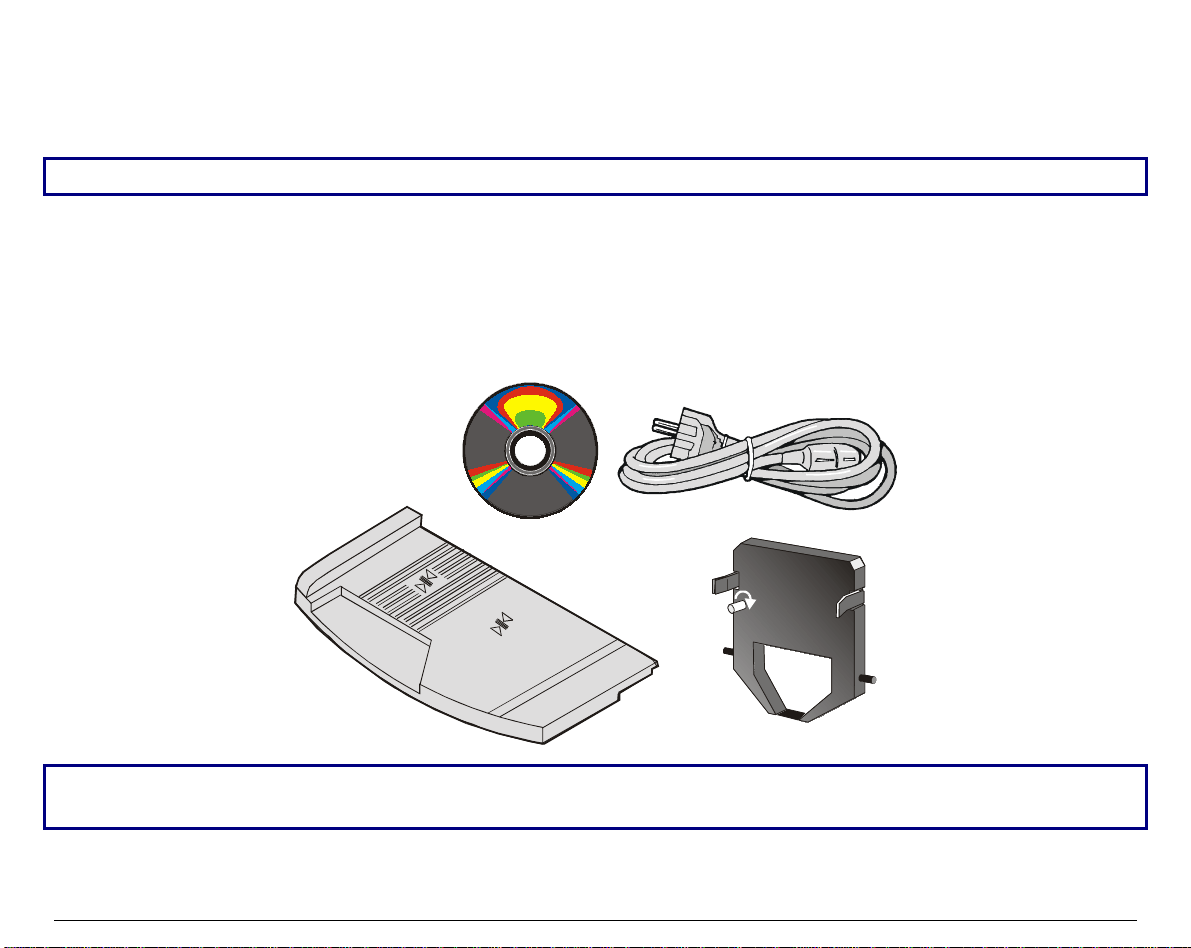
UUnnppaacckkiinngg tthhee PPrriinntteerr
Together with the printer the following items are included in the shipment box:
Notify any damage to your supplier.
• Paper stand
• Ribbon cartridge
• Power cable
• CD-ROM with the printer documentation and drivers.
Always keep the packing material in a safe place as you must repack the printer into it, when you
need to move it.
3
Page 6
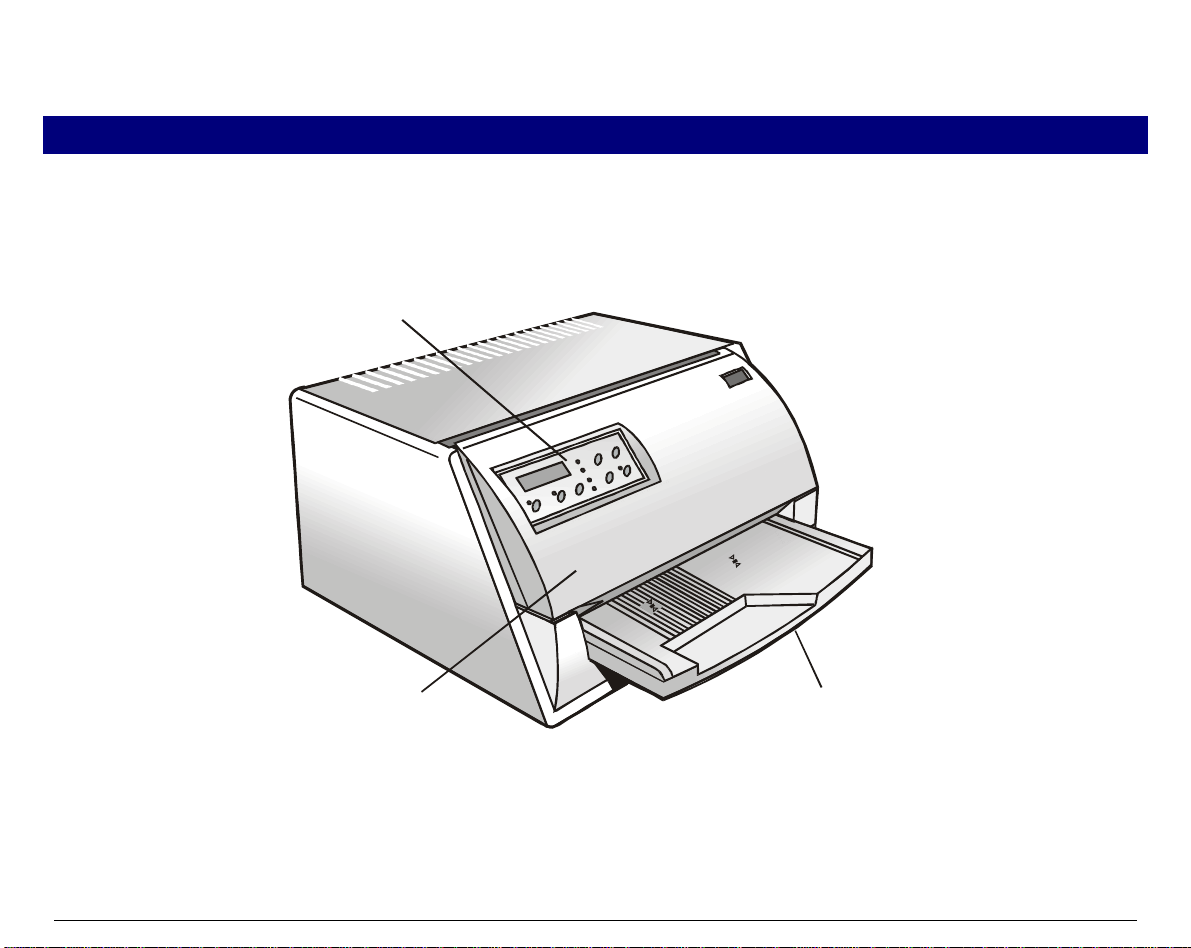
PPrriinntteerr PPaarrttss
Never remove any printer part unless it is expressly indicated in this manual.
FFrroonntt vviieeww
Op erator Pane l
Printer Cover
Paper Stand
4
Page 7
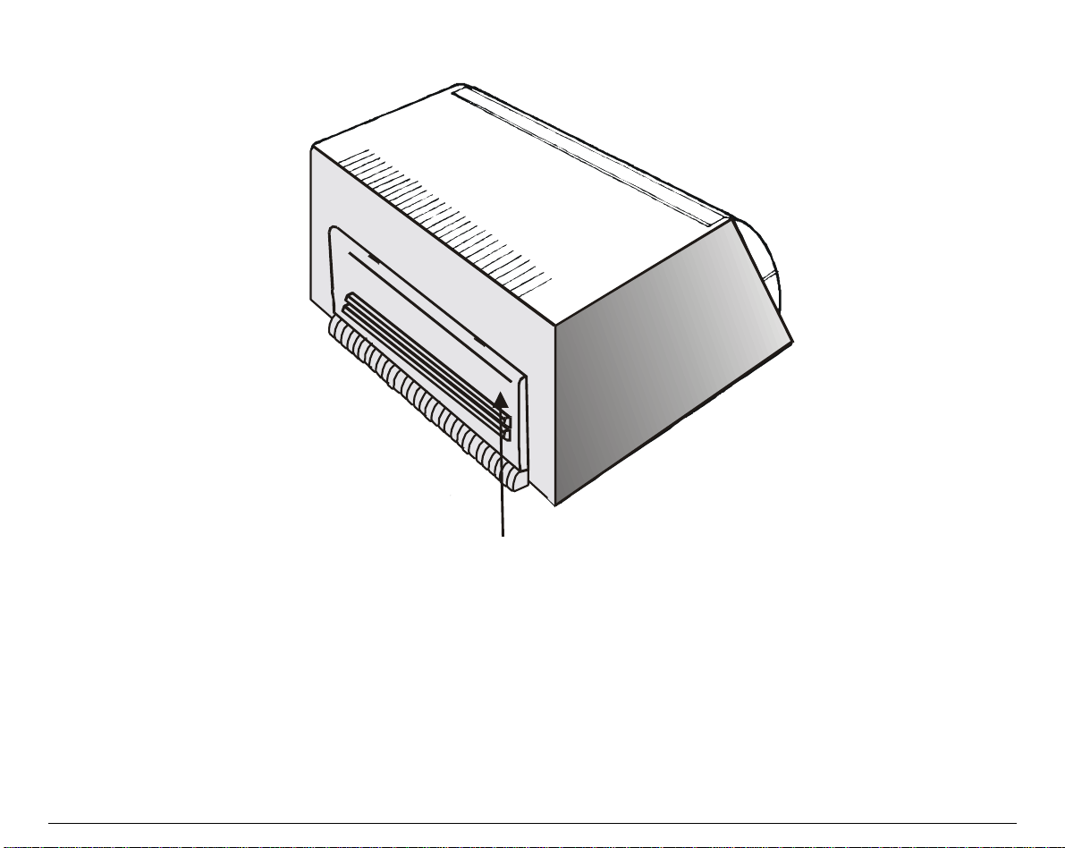
RReeaarr VViieeww
Rear cover
5
Page 8

PPrriinntteerr IInnssttaallllaattiioonn
CChhoooossiinngg aa SSuuiittaabbllee LLooccaattiioonn
Consider the following points when you choose the location for your printer:
• The distance between the printer and the host computer must not exceed the length of the
interface cable;
• The location must be sturdy, horizontal and stable;
• Your printer must not be exposed to direct sunlight, extreme heat , cold, dust or humidity;
• You need an AC power outlet compat ible with the plug of the printer’s power cord. The voltage
of the outlet must match the voltage shown on the printer’s Name Plate;
• When printing on standard paper formats, the pa per is parti a ll y ej ected on the rear side of the
printer. Make sure that behind the printer there is sufficient clearance to correctly move the
paper;
• Make sure that behind the printer there is sufficient clearance to easily load the fanfold
paper;
• Make sure that the power and interface cables do not hamper the fanfold paper while it is
loaded into the printer.
6
Page 9
IInnssttaalllliinngg tthhee PPaappeerr SSttaanndd
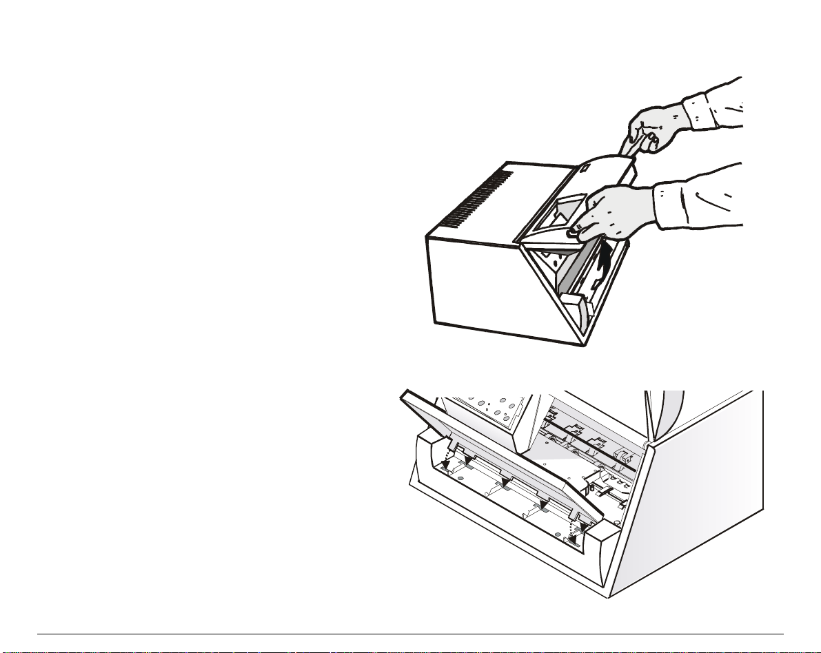
1. Open the printer cover.
2. Match the hooks on the lower side of the
paper stand with the clefts on the pri nter
front part.
7
Page 10
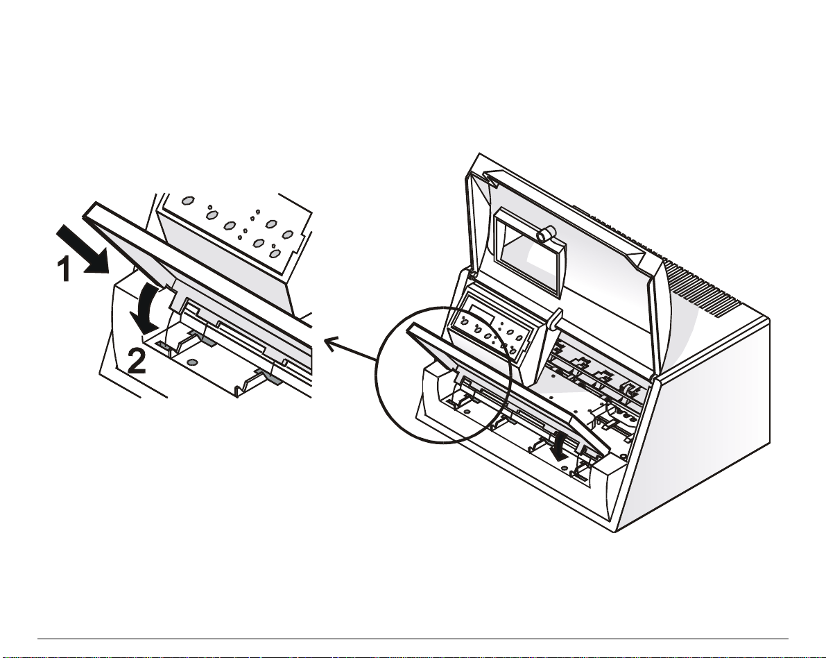
3. Holding the paper stand oblique i n sert the hooks into the printer clefts.
4. Lower the paper stand to hori zontal position making sure that the two holders on both sides
are correctly inserted into the corresponding slots. P ress the paper stand down until it clips
into place.
5. Close the printer cover.
8
Page 11
IInnssttaalllliinngg tthhee PPoowweerr CCaabbllee
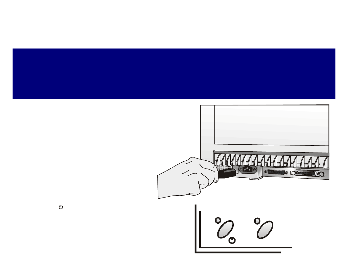
1. Find the power cable connector and the rating plate on the rear side of the printer.
Make sure that your power supply matches the power rating of the printer.
In case the power rating does not correspond DO NOT CONNECT THE PRINTER TO THE MAINS.
Consult your dealer for help.
Always use a grounded outlet.
2. Insert the power cable into the
connector on the printer and the other
end into a convenient mains outlet.
3. Press the key on the operator panel
to power the printer on.
LQ
9
Page 12
IInnssttaalllliinngg tthhee RRiibbbboonn CCaarrttrriiddggee
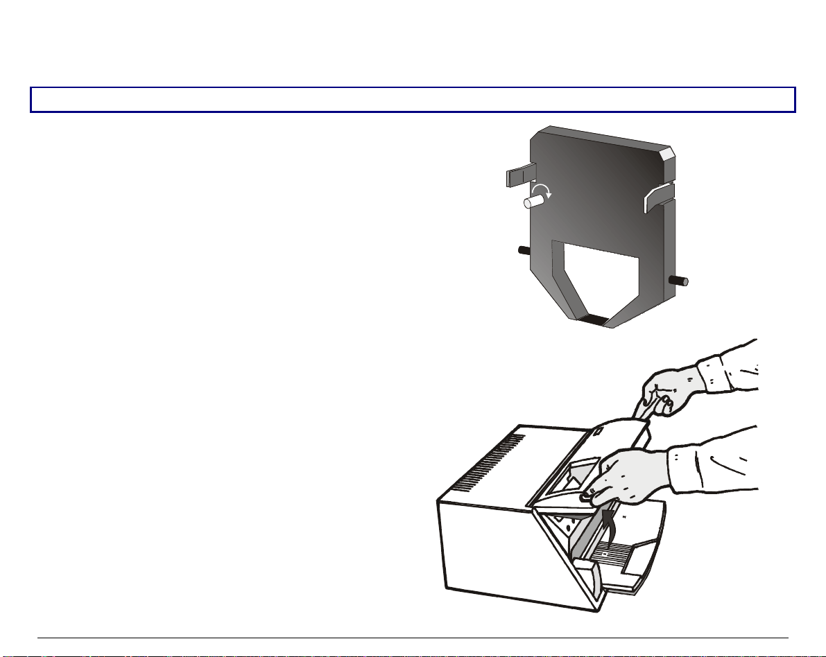
To install the ribbon cartridge, the printer must be powered on.
1. Remove the cartridge from its bag. Turn
the tension knob in the direction of the
arrow to tighten the ribbon.
2. Open the printer cover, the print head
moves to the ribbon installation position.
10
Page 13
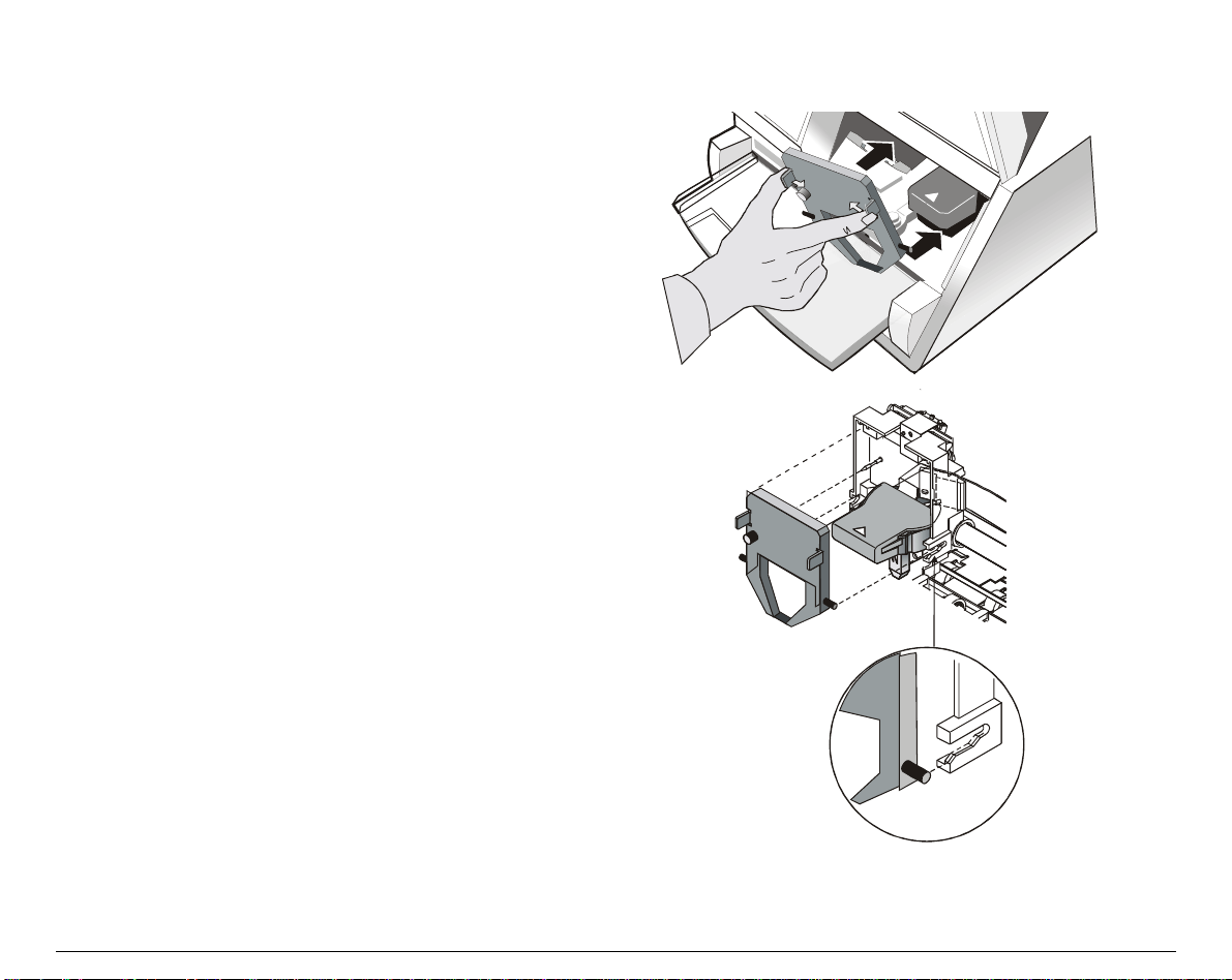
3. Hold the ribbon cartridge slightly
inclined with the ribbon mask in front of
the print head.
4. Insert the ribbon cartridge into the print
head carriage, leading the cartridge pins
into the fixing guides. In this way you
assure the correct ribbon mask posi tion in
front of the print head. Push the cartridge
onto the print carriage until it clicks into
place.
5. Turn the tension knob in the direction of the arrow to tighten the ribbon.
6. Close the printer cover.
11
Page 14
PPaappeerr HHaannddlliinngg
This printer is designed for versati le an relia ble paper handling. The flat-bed mechani sm allows
the handling of special documents, such as multiple invoices, postcards, labels and tickets.
The print head detects the paper edges automatically, the sheet can therefore be inserted in any
position within the detection area according to the rules described in the following paragraph.
The paper alignment sensors determine the alignment of the upper and left paper margins,
adjusting them if necessary.
The print head determines the thickness of the documents and matches its position.
LLooaaddiinngg PPaappeerr
LLooaaddiinngg CCuutt sshheeeett aanndd MMuullttiippaarrttss
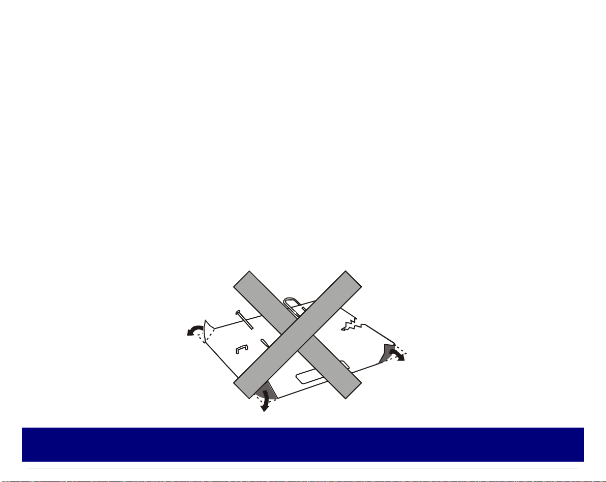
• The inserted documents must not have folds, tears, pins, clips, staples or any forei gn material.
If you insert damaged documents or paper with foreign material, you can seriously damage the
Clip
Pin
Staple
Foreign
material
printer.
12
Tear
Fold
Page 15
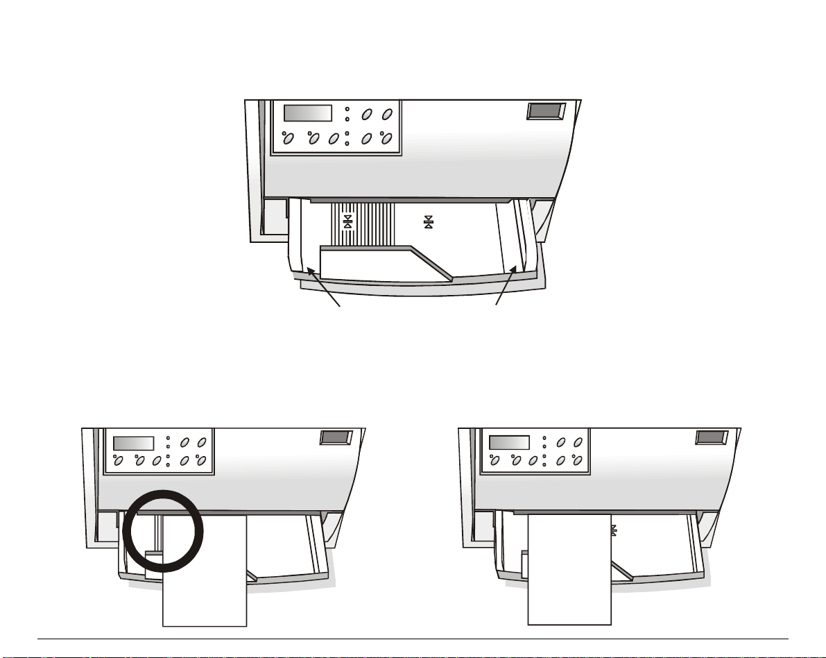
When inserting the paper into the printer, keep the follow ing points in mind:
• The document may not exceed the limits of the paper stand.
L e ft Limit
• The documents having a width of at least 90 mm must be inserted on the left hand side over
the grooved area on the paper stand.
The documents must cover the whole grooved area, otherwise the printer will not accept the
paper.
NO
13
Right Limit
OK
Page 16
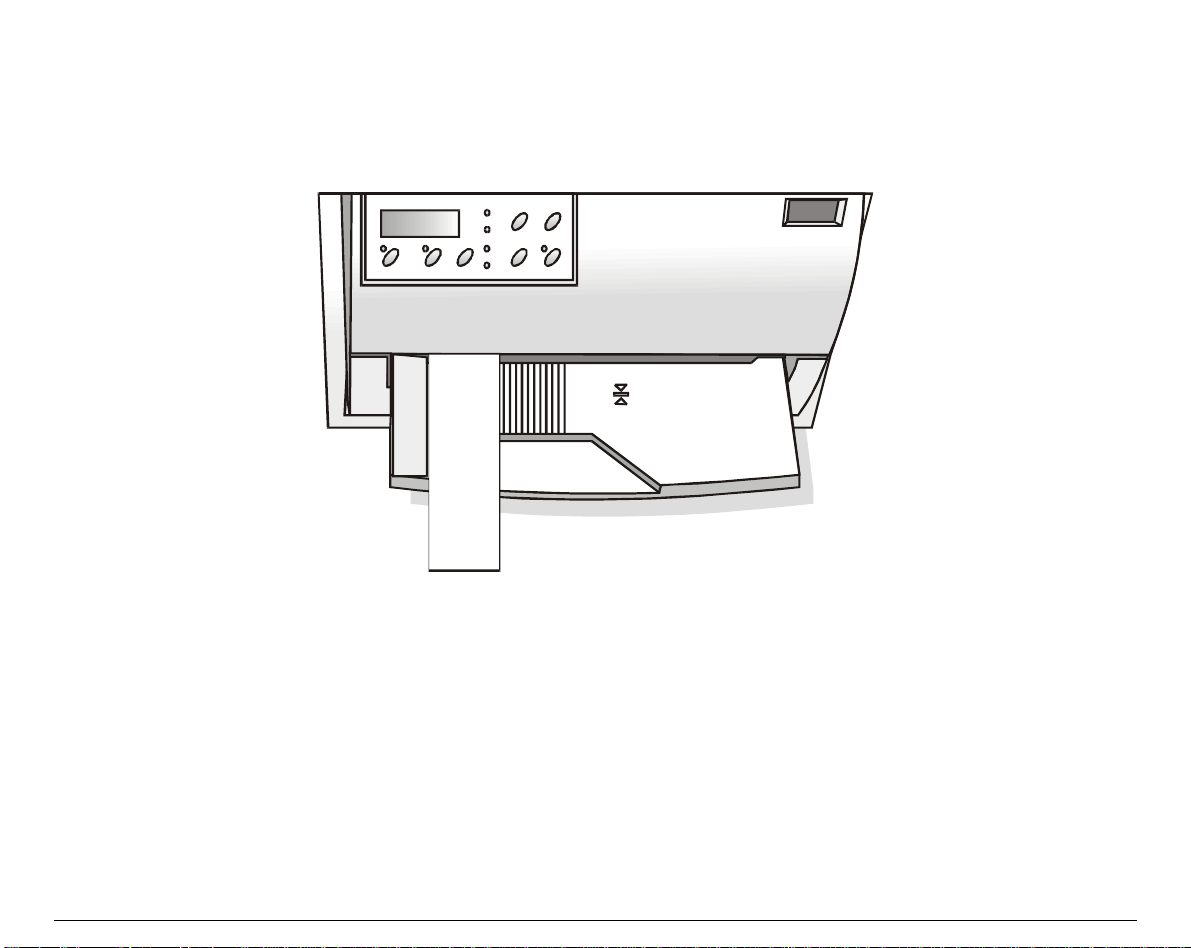
• To load the documents having a width of less than 90 mm:
− make sure that in the program menu the MANUAL LOADING item is enabled.
− hold the paper against the left paper gui de of the paper support while inserting it into the
printer
14
Page 17
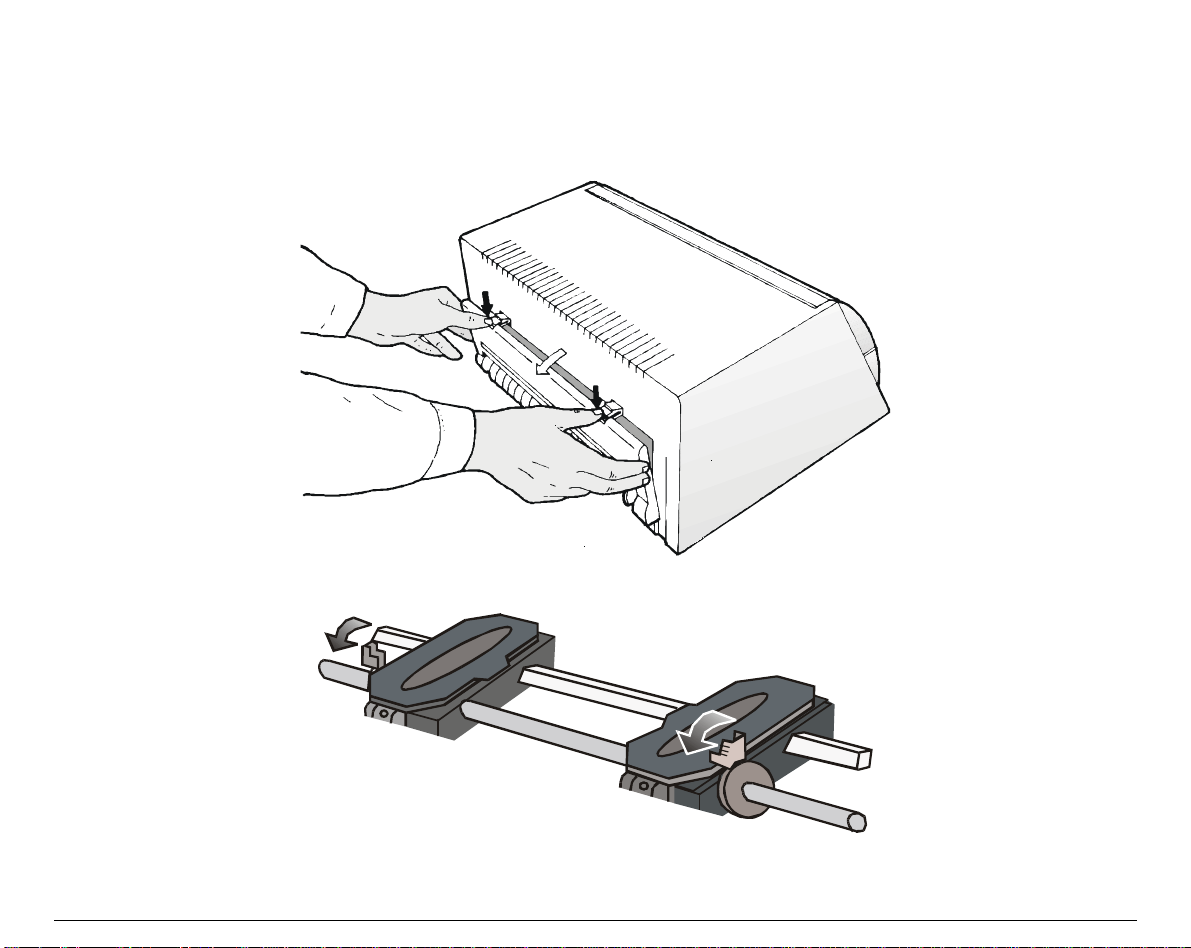
LLooaaddiinngg ffaannffoolldd ppaappeerr
The fanfold paper is loaded form the rear of the printer.
1. Lower the two levers of the rear printer cover and unhook it from the printer.
2. Unhook the right tractor moving the tractor lever towards the outside of the printer.
15
Page 18
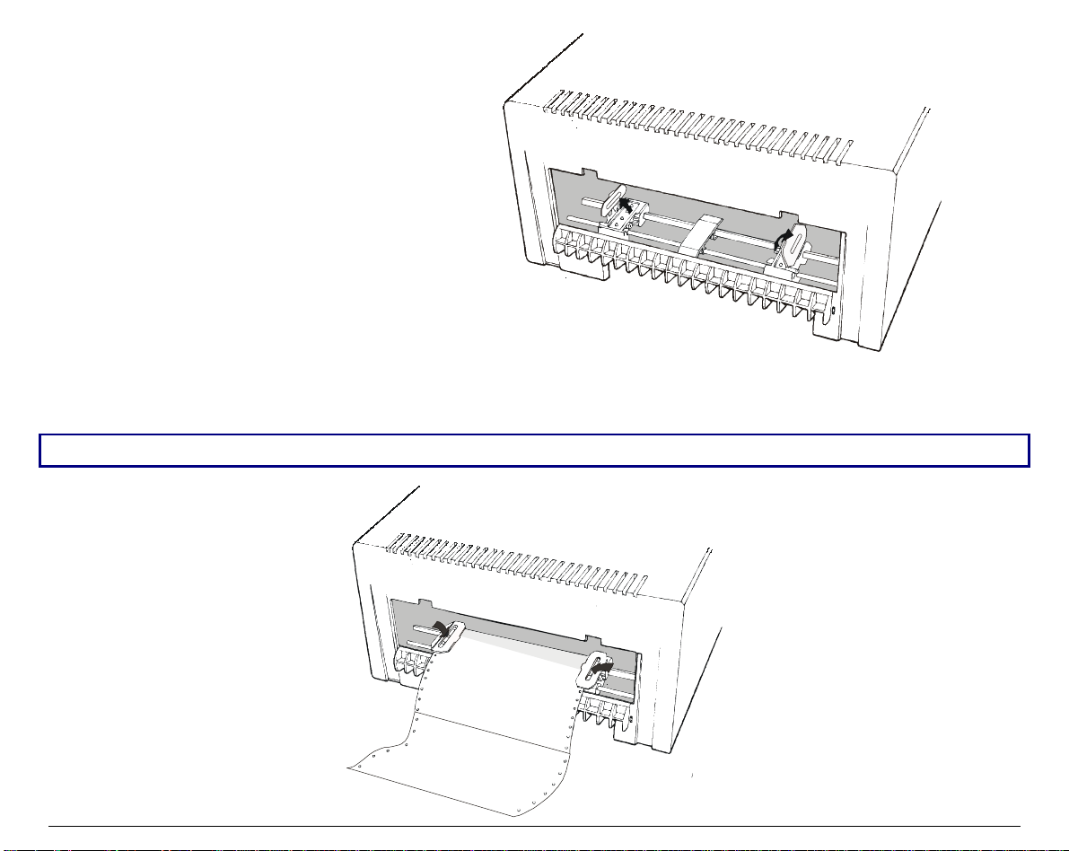
3. Open the two tractor covers.
4. Insert the perforation of the fanfold paper on the left paper tractor. Close the tractor door.
Insert the paper on the right paper tractor and close the tractor door.
The upper margin of the inserted paper should not exceed the tractors.
16
Page 19

Make sure, that the paper is inserted correctly (straight) .
5. Move the right paper tractor towards the right to slightly tighten the paper. Lock the tractor
in that position moving the tractor lever towards the inside of the printer.
Make sure, that the paper is not too taught, otherwise it may tear.
6. Hook the rear tractor cover into the corresponding slots (1) and push it against the printer
until both rear tractor levers (2) firmly hook into the printer.
2
1
7. Press
To remove the paper from the printer follow the abo ve sequence backwards.
LOAD/PARK
to load the paper into the printer.
17
Page 20

TThhee OOppeerraattoorr PPaanneell
The operator panel is located on the front left side of the printer and is composed of function keys
and leds with which you can easi ly check the pri nter status and sel ect the functions as described
below:
FFuunnccttiioonn kkeeyyss
LQ
Turns the printer on or off.
To turn the printer off, this key must be pressed for at least 3 seconds.
Toggles between Letter Quality and Draft printing mode.
This key is active, when the printer is offline or when the printer is online and no
print data are in the buffer.
When pressed while powering the printer on, selects the printer setup mode. See “Printer
Setup” later in this manual.
MICRO FEED
LF FF
PROGRA M
ONLINE
LQ
LOA D
PARK
P1
P2
P3
P4
18
Page 21

LOAD
PARK
If the paper path is empty, the fanfold paper is loaded into the printer (
function). This function is performed when the printer is online or offline.
If paper is loaded in the printer, pressing this key, the
function is performed:
PARK
LOAD
• a single sheet is loaded in the pr inter, p ress ing this key it is ejected;
• if the fanfold paper is loaded in the pri nter, pressing thi s key it is parked of the
printer is offline (
ON LINE
indicator off) or when the printer is online (
ON LINE
indicator on) and there are no data to be printed.
The PARK key has different effects depending on the selection for the PARK
MODE item in the Program Setup. See the description of this item lat er in this
manual.
↑
↓
LF
FF
Moves the fanfold paper forward in microsteps or conti nuously when keeping the
key pressed.
This key is enabled, when the printer cover is open.
Moves the fanfold paper backwards in microsteps or continuously when keeping
the key pressed.
This key is enabled, when the printer cover is open.
Moves the paper one line.
If fanfold paper is loaded, the key moves it forward one page.
If a single sheet is loaded, it is moved forward for the selected page length.
19
Page 22

PROGRAM
Selects one of the available configurations (P1, P2,
couple
P1/P3
or
) if the PROGRAM LOCKED parameter is not enabled.
P2/P4
P3
and
or a configuration
P4
This key is active, when the printer is offline or when the printer is online and no
print data are in the buffer.
When pressed while powering the printer on, selects the offset adjustment page.
See “Offset Adjustment” later in this manual.
ON LINE
Toggles the printer between online and offline status.
When pressed while powering the printer on, selects the Self Test printout. See
“Printing a Test Page” in this manual.
DDiissppllaayy
The display normally shows the printer name or is used to indicate fault states of the printer.
20
Page 23

LLeeddss
POWER
LQ
P1, P2,
P3, P4
On, if the printer is powered on.
On, if the Letter Quality mode is selected.
Indicate the currently selected configuration both in normal printing mode and
during the Printer Setup procedure. See “Printer Setup” later in this section.
If the INTERFACE TYPE function is set to auto+blink, when line 1 (parallel
interface) is selected for data transmission, the P1 indicator blinks.
If the INTERFACE TYPE function is set to auto+blink, when line 2 (serial interface)
is selected for data transmission, the P2 indicator blinks.
ON LINE
In case of fault condition P1, P2, P3 and P4 blink.
On, if the printer is online.
Off, if the printer is offline.
Blinks, when receiving printing data from host.
In case of a printer fault during the initialization of the LQ, P1, P2, P3, P4 and
ON LINE
indicators
blink contemporaneously. Turn the printer off and on again. If the problem is not solved, call the
Customer Service.
21
Page 24

SSooffttwwaarree DDrriivveerr SSeelleeccttiioonn
At this point it is necessary to configure your printer for your application package. The
installation procedures depend upon the host environment.
Together with the printer you recei ve a CD-RO M containing the pri nter drivers for the Wi ndows
environment. This printer supports the Plug&Play facility in the Windows95/98/2000®
environment.
If you want to install the printer in the Windows environment, insert the CD-ROM and follow
the instructions.
22
Page 25

CCoonnnneeccttiioonn ttoo tthhee HHoosstt
This printer can be connected to the host by means of a parallel standard Centronics or
bidirectional IEEE 1284 type interface or by means of the serial RS232C interface.
Proceed as follows:
Make sure that both the host and the printer are turned off.
1.
With the help of the following figure identify the connector for the interface you want to
2.
connect and insert the cable firmly into it.
Fix the parallel interface cable by means of the corresponding hooks or the serial cable
3.
tightening the screws on either side of the connector.
SERIAL
(L ine 2 )
Make sure, that the interface cables do not hamper the fanfold paper while it is loaded into the
printer.
23
PARALLEL
(L ine 1 )
Page 26

SSeettttiinngg tthhee IInntteerrffaaccee PPaarraammeetteerrss
PPaarraalllleell IInntteerrffaaccee
The parameters set for the parallel interface match most of the most common environments and
the printer can be used immediately after the connecti on to the host.
In case you need to modify the standard parameters see “Printer Setup” later in this section.
SSeerriiaall IInntteerrffaaccee
Because of the great variety of the possible connection configurations, when you use the serial
interface you will need to set the parameters accordingly.
To assure a correct functioning of the printer connected through the serial interface, the
transmission parameters set for the printer must match the values set for the host. Check the
interface settings on the host and proceed as follows:
1. Press the LQ key while powering the printer on a nd keep it pressed until all leds turn briefly on.
The printer enters the Setup mode.
2. Insert a blank sheet in A4 or Letter format. The printer loads the sheet and stops. The
P3
and
leds are lit.
P4
P1, P2,
3. Press the
4. Press the LQ key. The printer prints the first configuration sheet.
PROGRAM
key once. The
P1, P2, P3
and
24
leds are unlit.
P4
Page 27

5. To change the values of the serial interface parameters, fill in the marker ( ) beside the value
you want to set with a black or blue ball-point pen or a fiber-pen.
Do not use pencils.
W ORD LENGTH ( ) ( )
disable d * enabled
BAUD RATE ( ) ( )
PA RIT Y BIT ( ) ( ) ( )
disable d * enabled
DTR XON/XOFF* XON/XOFF + DTR
If more than one value is set for a parameter, the printer ignores these parameters and maintains
the currently set value.
Do not fill in the marker beside the title of the preprinted form, otherwise the printer will not be
able to read that page.
6. Once the serial interface parameters have been signed, insert the sheet back into the printer.
7. The printer reads the selected values on the configuration sheet and sets them. The settings
are confirmed by a # symbol printed on the left of the corresponding marker.
The printer then returns to normal functioning mode.
For a complete description of the printer setup procedure see the paragraph “Printer Setup” later
in this manual.
25
Page 28

PPrriinnttiinngg aa TTeesstt PPaaggee
It is now useful to test, i f the printer has been correctly i nstalled. F or this purpose print the self
test page as follows.
1. Press the
ON LINE
key while powering the printer on and hol d the key pressed until all leds
turn briefly on.
2. Insert a single sheet in A4 or Letter format.
The printer prints the Self-T est page. Check that the printout is correct. The follow ing printout
example shows also the printer setup default values.
ELF TEST
S
FB300 :
CONFIGURATION SETUP
DISPLAY LANG. English INTERFACE TYPE automatic
PROGRAM progr.1 INPUT BUFFER 16 Kb
PROGRAM LOCKED no AUTOFEED SIGNAL disabled
ERROR BUZZER 1 beep SLCT-IN SIGNAL disabled
JOB BUZZER No beep IGNORE PE enabled
SECURITY MODE enabled BUFFER CONTROL XON/XOFF
AUTO GAP OFFSET +0.000 mm ROBUST XON enabled
GET EDGE QUOTE 1/2” WORD LENGTH 8 bit
SKIP PERFORATION disabled BAUD RATE 9600 bps
TEAR ADJUST +0,00 mm PARITY BIT none
Code Version Vx.x xxxxxxxx CharGen:xxxxxxxx ver. x.xx
26
Page 29

PROGRAM SETUP
PROGRAM 1 PROGRAM 2 PROGRAM 3 PROGRAM 4
PROTOCOL IBM XL24E EPSON 570 IBM XL24E EPSON 570
FONT Draft Draft Draft Draft
HORIZONTAL PITCH 10 cpi 10 cpi 10 cpi 10 cpi
VERTICAL PITCH 6 lpi 6 lpi 6 lpi 6 lpi
LOCK no lock no lock no lock no lock
FORM LENGTH A4 A4 #lines #lines
0 0 72 72
LEFT MARGIN 0 0 0 0
RIGHT MARGIN 96 96 96 96
TOP MARGIN 0 0 0 0
BOTTOM MARGIN 0 0 0 0
IBM C-SET IBM set 1 IBM set 1 IBM set 1 IBM set 1
IBM COMPRESS 17.1 cpi 17.1 cpi 17.1 cpi 17.1 cpi
EPSON C-SET graphic graphic graphic graphic
NATION C-SET USA USA USA USA
CODE PAGE CP437 CP437 CP437 CP437
LINE MODE LF=LF, CR=CR LF=LF, CR=CR LF=LF, CR=CR LF=LF, CR=CR
WRAP MODE autowrap autowrap autowrap autowrap
SLASHED ZERO no no no no
PRINT DIRECTION sw control sw control sw control sw control
EJECT ON FF yes yes yes yes
CUT SHEET EJECT on front On front on front on front
PARK MODE manual imm. manual imm. manual imm. manual imm.
TEAR MODE manual manual manual manual
MANUAL LOADING disabled
ALIGN MODE fast fast fast fast
GAP MODE auto auto auto auto
VERT.POS 1/10” 0 0 0 0
VERT.ADJ 1/60” 0 0 0 0
HORIZ.POS 1/10” 0 0 0 0
HORIZ.ADJ 1/60” 0 0 0 0
disabled
disabled
disabled
27
Page 30

PPrriinntteerr SSeettuupp
The default configuration of this printer matches most of the commonly used environments, but
it may be necessary to change some pri nter parameters. For this purpose it is necessary to use
preprinted forms to be used with the printer in configurat ion mode.
The following is the complete description of the Setup Procedure.
The detailed description of the parameters that can be set on the various preprinted fo rms are
described in the “Setup Parameters” paragraph, later in this manual.
To enter the Printer Setup Mode press and hol d the LQ key for at least 1 second while pow ering
the printer on. The printer enters the Setup Mode.
28
P1, P2, P3
PPrriinnttiinngg tthhee PPrriinntteerr SSeettuupp FFoorrmmss
If you already have the preprinted forms for the printer setup, go to “Filling in the Printer Setup
Forms” later in this manual.
Insert a blank sheet in A4 or Letter format. The printer loads the sheet and stops. The
and P4 leds are lit.
The
ON LINE, PROGRAM
If the LQ key is pressed immediately after the printer enters in Setup Mode, all printer setup
and LQ keys are enabled.
modules are printed.
Page 31

If you press the
ON LINE
key:
• the printer self-test is printed. See “Printing a Test Page” before in this manual. In this way it
is possible to check the current printer parameters.
• once the self-test is finished, the printer remains in Setup Mode.
If you press the
PROGRAM
key:
• the Px leds change and you can select the Setup Page you want to print as follows:
P1
P2
P3
P4
P1
P2
P3
P4
P1
P2
P3
P4
= lit
= unlit
All setup pages
Configuration page
Program 1 page
P1
P2
P3
P4
P1
P2
P3
P4
P1
P2
P3
P4
Program 2 page
Program 3 page
Program 4 page
The printer setup forms contain all printer parameters and the values that can be set. The
current value is indicated by an asterisk (*).
For a detailed description of the parameters and the settings see “Setup Parameters” later in this
manual.
29
Page 32

Each printer setup form is identified by a ma rker in the upper left corner of the page as follows:
Configuration Setup
Program 1
Program 2
Program 3
Program 4
If you press the LQ key:
The printing of the pri nter setup forms starts. The forms are printed according to the selection
made with the
PROGRAM
If you select one of the Program couples
key.
P1/P3
or
P2/P4
you can define one parameters set for
printing on cut sheets and one for fanfold. P1 and P2 define the values for printing on cut sheets,
whereas P3 and P4 define the printing parameters for the fanfold paper.
The program couples may be selected only if the same emulation is selected for the two
programs.
The selection of the Program Setup is made simply pressing the
PROGRAM
key. When passing
from one Program Setup to another, the printer resets before setting the parameters as defined
in the new program setup.
30
Page 33

FFiilllliinngg iinn tthhee PPrriinntteerr SSeettuupp FFoorrmmss
To change the values of the parameters, fill in the marker ( ) beside the value you want to set
with a black or blue ball-point pen or a fiber-pen.
Do not use pencils.
AU TOFE ED SIG N A L ( ) ( )
SLCT -IN SIGNAL ( ) ( )
BUFFER CONTROL ( ) ( ) ( )
disabled * enabled
disabled * enabled
DTR XON/XOFF* XON/XOFF +
If more than one value is set for a parameter, the printer ignores these parameters and maintains
the currently set value.
Do not fill in the marker beside the title of the preprinted form, otherwise the printer will not be
able to read that page.
RReeaaddiinngg tthhee PPrreepprriinntteedd FFoorrmmss
When the Printer Setup Forms have been filled in, insert them back into the printer. The printer
is able to recognize the Setup Forms by means of the markers on these pages. The printer reads
the values marked for the various parameters and configures the printer accordingly.
The settings are confirmed by a # symbol printed on the left of the corresponding marker.
31
Page 34

PPrriinntteerr SSeettuupp FFllooww CChhaarrtt
Printer Powered-off
Self Test
PROGRAM
ON L I N E
PROGRAM
P1
P2
P3
P4
PROGRAM
P1
P2
P3
P4
P1
P2
P3
P4
PROGRAM
P1
P2
P3
P4
LQ
+
LQ
LQ
Normal M ode
LQ
+
!
+
+
PROGRAM
P1
P2
P3
P4
LQ
+
LQ
P1
P2
P3
P4
PROGRAM
LQ
32
Page 35

SSeettuupp PPaarraammeetteerrss
The following is a listing of the setup parameters.
Configuration Sheet
Setup Parameter Values Description
RESTORE TO MFG
DISPLAY LANG. English, Italian,
PROGRAM progr.1, progr.2,
PROGRAM LOCKED no, yes Locks the program setup selection. In case the lock is ‘enabled’ the
no
all
config
prog.1, prog. 2,
prog.3, prog 4
German, French,
Spanish
progr.3, progr.4,
progr.1/3, progr.2/4
The selected values are not set to factory defaults.
The values set in all printer setups are reset to factory default
values.
The values set in the configuration setup are reset to factory default
values.
The values set in the corresponding program setup are reset to the
factory default values.
Defines the language of the display messages.
Defines the default Program Setup or Setup couple. The program
couples may be selected only if the same emulation has been
selected for the two setups.
program setup cannot be changed pressing the PROGRAM key.
ERROR BUZZER 1 beep, no beep Selects the behavior of the buzzer in case of an error.
JOB BUZZER no beep, 1 beep,
continuous
Selects the behavior of the buzzer when a new print job begins: no
signal (
(
continuous
no beep
), one beep (
).
1 beep
) or a continuous beep
33
Page 36

Setup Parameter Values Description
INTERFACE TYPE parallel, serial, automatic,
auto+blink
Selects the interface type. In case of ‘automatic’ the interface
type is selected by the printer depending on data coming from
host. When the
auto+blink
item is selected, the P1 and P2
leds blink to indicate which interface is selected: P1 blinks
when the parallel interface is selected, whereas P2 blinks,
when the serial interface is selected.
INPUT BUFFER 1 Kb, 8 Kb, 16 Kb, 32 Kb Selects the buffer size.
IGNORE PE enabled, disabled Selects whether the printer signals the paper empty condition
(
disabled
AUTOFEED SIGNAL disabled, enabled The parallel interface uses (
(
disabled
SLCT-IN SIGNAL disabled, enabled The parallel interface uses (
(
disabled
BUFFER CONTROL DTR+SRTS, SRTS,
Selection of the buffer protocol.
) or not (
enabled
).
enabled
) the AUTOFEED signal.
enabled
) the SELECT-IN signal.
) or does not use
) or does not use
XON/XOFF,
XON/XOFF+DTR+SRTS
ROBUST XON enabled, disabled Perform the Robust XON (
enabled
) or not (
disabled
).
WORD LENGTH 7 bit, 8 bit Sets the number of the data bits.
BAUD RATE 600 - 38400 bps Sets the data transfer rate.
PARITY BIT even, odd, none Selects the parity control for the data.
34
Page 37

Setup Parameter Values Description
SECURITY MODE enabled, disabled Enables or disables the security actions that assure protection
against paper jams. If disabled, the paper handling is faster.
AUTO GAP OFFSET -0,075 mm, -0.050 mm,
Sets the automatic gap offset to one of the given values.
-0.025 mm, +0.000 mm,
+0.025 mm, +0.050 mm,
+0.075 mm, +0.100 mm
GET EDGE QUOTE 0/2”, 1/2”, 2/2”, 3/2”, 4/2”,
5/2”, 6/2”, 7/2”
Sets the position in which the left paper edge is checked. If set
to 0, the check is performed at the first line. The other values
correspond to the physical distance from the first line.
SKIP PERFORATION disabled, enabled If the movement of the paper perforation under the print head
is critical, select
enabled
to avoid the paper to get torn. The
print head lifts up while the paper perforation passes through.
TEAR ADJUS T -0,85 mm, -0,56 mm,
-0,28 mm, +0,00 mm,
If
disabled,
Sets the paper tear-off position by aligning the paper with the
tear-off edge.
the print head stays in position.
+0,28 mm +0,56 mm,
+0,85 mm
35
Page 38

PROGRAM 1
PROGRAM 3
PROGRAM 2
PROGRAM 4
Setup Parameter Values Description
PROTOCOL EPSON 570, IBM X24E,
IBM X24E AGM, IBM 2390
FONT Draft, Courier, OC R-B ,
Gothic, Prestig e, Pr ese nt,
OCR-A, Script, Bo ldfa ce
HORIZONTAL PITCH 10 cpi, 12 cpi, 15 cpi, 17 cpi,
20 cpi
VERTICAL PITCH 5 lpi, 6 lpi, 8 lpi, Selects the line spacing in lines per inch (lpi).
LOCK no lock, font, hor. pitch,
font+hor. pitch
Defines the printer protocol.
Selects the font.
Selects the character spacing in characters per inch (cpi).
The following selections made via operator panel may be
locked: font, horizontal pitch (
and horizontal pitch (
font+hor. pitch)
hor.pitch
), or both the font
. The locked
settings cannot be changed via software commands.
FORM LENGTH # lines, A4, letter, A5, legal Sets the page length in number of lines or standard formats
A4, Letter, A5 or Legal. If you select
# lines
, you must
indicate the number of lines you want to set in the scheme
below this selection. The values range between 0 and 255.
To set the values combine the numbers considering that
the first line corresponds to the hundreds, the second line
to the tens and the third line to the units. See the example
below.
36
Page 39

Example:
How to set the form length to 82 lines:
(
FORM LENGTH
# lines A4 letter A5 legal
0 1 2 3 4 5 6 7 8 9
100 x ( ) ( )
10 x ( ) ( ) ( ) ( ) ( ) ( ) ( ) ( )
1 x ( ) ( )
Setup Parameter Values Description
(
( ) ( ) ( ) ( )
(
( ) ( ) ( ) ( ) ( ) ( ) ( )
(
(
( )
(
LEFT MARGIN 10 x
1 x
Sets the left margin in number of columns. The values range between 0
and 90. To set the values combine the numbers considering that the first
line corresponds to the hundreds, the second line to the tens and the
third line to the units. See the example below.
Example:
How to set the Left Margin to 20.
LEFT MARGIN
0 1 2 3 4 5 6 7 8 9
10 x ( ) ( )
(
1 x
( ) ( ) ( ) ( ) ( ) ( ) ( ) ( ) ( )
(
(
( ) ( ) ( ) ( ) ( ) ( ) ( )
(
Setup Parameter Values Description
RIGHT MARGIN 100 x
10 x
1 x
Sets the right margin in number of columns. The values range between 0 and
190. The physical position of margin depends on the current character
spacing. To set the values combine the numbers considering that the first line
corresponds to the hundreds, the second line to the tens and the third line to
the units. See the example below:
37
Page 40

Example:
How to set the Right Margin to 101.
RIGHT MARGIN
0 1 2 3 4 5 6 7 8 9
100 x ( )
10 x
1 x ( )
(
Setup Parameter Values Description
(
(
(
( ) ( ) ( ) ( ) ( ) ( ) ( ) ( ) ( )
(
( ) ( ) ( ) ( ) ( ) ( ) ( ) ( )
(
TOP MARGIN 10 x
1 x
Sets the top margin in number of lines. The values range between 0 and 90.
To set the values combine the numbers considering that the first line
corresponds to the hundreds, the second line to the tens and the third line to
the units. See the example below.
Example:
How to set the Top Margin to 15.
TOP MARGIN
0 1 2 3 4 5 6 7 8 9
10 x ( )
1 x ( ) ( ) ( ) ( ) ( )
Setup Parameter Values Description
BOTTOM MARGIN 10 x
(
( ) ( ) ( ) ( ) ( ) ( ) ( ) ( )
(
(
( ) ( ) ( ) ( )
(
Sets the bottom margin in number of lines. The values range between 0 and
90. To set the values combine the numbers considering that the first line
1 x
corresponds to the hundreds, the second line to the tens and the third line to
the units. See the example below.
38
Page 41

Example:
How to set the bottom margin to 34 lines:
BOTTOM MARGIN
0 1 2 3 4 5 6 7 8 9
10 x ( ) ( ) ( )
1 x ( ) ( ) ( ) ( )
(
( ) ( ) ( ) ( ) ( ) ( )
(
(
( ) ( ) ( ) ( ) ( )
(
Setup Parameter Values Description
IBM C-SET IBM set 1, IBM se t 2 Selects the IBM character set.
IBM COMPRESS 17.1 cpi, 20 cpi Selects the pitch for the compressed mode
printing in IBM emulation.
EPSON C-SET italic, graphic Selects italic or graphic Epson character set.
NATION C-SET USA, FRANCE, GERMANY, ENGLAND,
DENMARK1, SWEDEN, ITALY, SPAIN1,
JAPAN, NORWAY, DENMARK2,
SPAIN2, LATIN A1
Selects the national character sets.
CODE PAGE CP437, CP437G, 96GREEK, CP850,
CP851, CP852, CP853, CP855, CP857,
CP858, CP860, CP862, CP863, CP864,
CP865, CP866, CP867, CP876, CP877,
CP1098, CP1250, CP1251, CP1252,
GOST, TASS, MAZOWIA, CP437SL,
UKRAIN, 8859/1, 8859/2, 8859/3, 8859/4,
8859/5, 8859/6, 8859/7, 8859/8, 8859/9,
8859/15, ROMAN-8, ID 12, CP874, ID 14,
ID 17, SANYO, K U, P HIL IP
39
Selects the code page for both the IBM and the
EPSON emulations.
Page 42

Setup Parameter Values Description
LINE MODE LF=LF, CR=CR
If the printer receives a LF code (LF), it only performs a line feed. If
the printer receives a CR code (CR), it only performs a carriage
return.
CR=LF+CR
LF=LF+CR
LF&CR=LF+CR
If the printer receives a CR code (CR), it performs a carriage return
followed by a line feed. If the printer receives a LF code (LF), it
performs a line feed.
If the printer receives a LF code (LF), it performs a line feed followed
by a carriage return. If the printer receives a CR code (CR), it only
performs a carriage return.
If the printer receives a LF code (LF) or a CR code (CR), it performs
both a line feed and a carriage return.
WRAP MODE truncate, autowrap The data exceeding the line length are truncated (
printed on the following line (
autowrap
).
truncate
SLASHED ZERO no, yes Selects the printing character for zero, with a slash (
(no).
PRINT DIREC TION unidir., bidir.,
sw control
Selects the printing direction of the print head: unidirectional
(
unidir
control
.), bidirectional (
).
bidir
.) or selected via software (
) or without
yes
) or
sw
EJECT ON FF no, yes Performs a form feed according to the selected page format (no) or
ejects a cut sheet loaded into the printer (
yes
).
CUT SHEET EJECT on front, on rear Selects whether the cut sheet loaded into the printer is ejected
towards the front or the rear of the printer. The selection of the paper
ejection towards the rear of the printer should be selected only for
paper with a length of at least 14 cm (5,5 inch).
40
Page 43

Setup Parameter Values Description
PARK MODE
immediate
When pressing the PARK key or receiving a park command, the printer
immediately parks the paper.
manual imm.
When pressing the PARK key, the printer automatically parks the
paper. When receiving a park command via software:
1. If the current page is not empty (there is printing data or paper
movement commands have been issued), a form feed is performed.
2. The paper is moved to the tear-off position.
3. The P1, P2, P3 and P4 leds blink.
4. When the ON LINE key is pressed the printer parks the paper.
after tear When pressing the PARK key or receiving a park command via
software:
1. If the current page is not empty (there is printing data or paper
movement commands have been issued), a form feed is
performed.
2. The paper is moved to the tear-off position.
3. The P1, P2, P3 and P4 leds blink.
4. When the ON LINE key is pressed the printer parks the paper.
TEAR MODE auto 1s, auto 2s,
auto 3s, auto 4s,
auto 5s, manual,
no tear/reverse
Selects the way the tear mode is performed. Selecting
auto 2s, auto 3s, auto 4s, or auto 5s
auto 1s,
, the printer moves
the paper in the tear-off position and back to the printing position after
the corresponding number of seconds. Selecting manual, the tear-off is
performed manually, pressing the ON LINE key. Selecting
reverse
, the printer does not perform the tear-off function (this is
no tear/
useful, when printing on labels).
41
Page 44

Setup Parameter Values Description
MANUAL LOADING enabled, disabled Selects the manual loading mode. Setting it to
loads any kind of document according to the described procedures.
Select
With this selection it is not possible to load documents with a width of
less than 90 mm.
ALIGN MODE fast, normal Selects the paper alignment mode. Selecting
less checks on the alignment, whereas, if you need a particularly
precise alignment of the documents, select
GAP MODE
OOffffsseett AAddjjuussttmmeennttss
auto, fix Selects, whether the print gap is sensed for each inserted sheet (
or only for the first sheet after the printer power on (
is sensed separately for the cut sheet and the fanfold paper.
disabled
, when a more precise paper alignment is necessary.
normal
enabled
fast
the printer
the printer performs
.
auto
). The print gap
fix
)
For a precise adjustment of the position of the printed characters on a preprinted form, this
printer allows to easily adjust the first line and the first printing column as follows:
1. Press the
PROGRAM
key while powering the printer on.
2. Insert a blank sheet into the printer.
The following sheet will be printed:
42
Page 45

OFFSET TUNING SETUP
Vertical Position Offset (1/10 INCH)
PROGRAM 1 ( )* ( ) ( ) ( ) ( ) ( ) ( ) ( ) ( ) ( )
PROGRAM 2 ( )* ( ) ( ) ( ) ( ) ( ) ( ) ( ) ( ) ( )
PROGRAM 3 ( )* ( ) ( ) ( ) ( ) ( ) ( ) ( ) ( ) ( )
PROGRAM 4 ( )* ( ) ( ) ( ) ( ) ( ) ( ) ( ) ( ) ( )
0 +1 +2 +3 +4 +5 +6 +7 +8 +9
Vertical Offset Tuning (1/60 INCH)
X
X
X
X
PROGRAM 1 ( ) ( ) ( ) ( ) ( ) ( ) ( )* ( ) ( ) ( ) ( ) ( ) ( )
PROGRAM 2 ( ) ( ) ( ) ( ) ( ) ( ) ( )* ( ) ( ) ( ) ( ) ( ) ( )
PROGRAM 3 ( ) ( ) ( ) ( ) ( ) ( ) ( )* ( ) ( ) ( ) ( ) ( ) ( )
PROGRAM 4 ( ) ( ) ( ) ( ) ( ) ( ) ( )* ( ) ( ) ( ) ( ) ( ) ( )
-6 -5 -4 -3 -2 -1 0 +1 +2 +3 +4 +5 +6
Horizontal Position Offset (1/10 INCH)
PROGRAM 1 ( ) ( ) ( ) ( ) ( ) ( ) ( )* ( ) ( ) ( ) ( ) ( ) ( ) ( ) ( ) ( )
PROGRAM 2 ( ) ( ) ( ) ( ) ( ) ( ) ( )* ( ) ( ) ( ) ( ) ( ) ( ) ( ) ( ) ( )
PROGRAM 3 ( ) ( ) ( ) ( ) ( ) ( ) ( )* ( ) ( ) ( ) ( ) ( ) ( ) ( ) ( ) ( )
PROGRAM 4 ( ) ( ) ( ) ( ) ( ) ( ) ( )* ( ) ( ) ( ) ( ) ( ) ( ) ( ) ( ) ( )
-6 -5 -4 -3 -2 -1 0 +1 +2 +3 +4 +5 +6 +7 +8 +9
Horizontal Offset Tuning (1/60 INCH)
PROGRAM 1 PROGRAM 2 PROGRAM 3 PROGRAM 4
X ( ) ( ) ( ) ( ) -6
X ( ) ( ) ( ) ( ) -5
X ( ) ( ) ( ) ( ) -4
X ( ) ( ) ( ) ( ) -3
X ( ) ( ) ( ) ( ) -2
X ( ) ( ) ( ) ( ) -1
X ( ) * ( ) * ( ) * ( ) * 0
X ( ) ( ) ( ) ( ) +1
X ( ) ( ) ( ) ( ) +2
X ( ) ( ) ( ) ( ) +3
X ( ) ( ) ( ) ( ) +4
X ( ) ( ) ( ) ( ) +5
X ( ) ( ) ( ) ( ) +6
X
X
X
X
X
X
X
X
X
43
Page 46

The Vertical Offset Tuning v alues correspond to 1/60 inches and set the vertical offset of
the first print line starting from the default standard position at 1 mm from the upper paper
margin.
The Horizontal Offset Tuning values correspond to 1/60 inches and set the horizontal
offset of the first print line starting from the default standard position at 3 mm from the left
paper margin.
If you need to chang e the default position of the first print line the vertica l offset can be set in
the Vertical Position Offset lines and/or the horizontal offset in the Vertical
Position Offset lines. Both these values correspond to 1/10 inch values.
3 mm
HORIZ
DEF.
POS
X
X
X
X
X
Horizontal Offset Tuning
1 mm
X
X
X
X
X
VERT. DEF. POS
= FIRST PRINT POSIT ION
X
X
X
X
X
X
X
X
X
Vertical Offset Tuning
X
Vertical Offset Tuning
3. Fill in the marker corresponding to the value you want to set and reinsert the sheet into the
printer. The printer reads the selected values and sets them.
4. Turn the printer off.
44
Page 47

TTrroouubblleesshhoooottiinngg
CClleeaarriinngg PPaappeerr JJaammss
The straight paper path of this printer is designed for trouble-free handling of a great variety of
documents.
In case a paper jam condition occurs, proceed as follows:
1. Open the printer cover.
2. Pull the lever on the right inner side of the printer towards the printer front side to open the
paper path and with the other hand hold the paper path cov e r.
45
Page 48

3. Remove the jammed paper.
4. In case it is not possible to remove the
jammed paper because you cannot reach it
with your hand or it is embedded so that you
cannot move it, rotate the cog-wheel beside
the paper path lever to free the paper.
46
Page 49

5. To close the paper path, push the paper path cover down until it locks in position.
47
Page 50

PPrriinntt QQuuaalliittyy PPrroobblleemmss
The following table is useful for identifying and solve print quality problems.
Problem Cause Solution
Fading print The ribbon is not fed Check that the ribbon is correctly inserted. See
The ribbon is used up or
torn
Paper
damaged after
printing
The paper does not
correspond to the
specifications given in
this manual or was not
loaded according to the
indications given
“Installing the Ribbon Cartridge”.
Turn the ribbon tension knob to verify, that the
ribbon is not blocked.
If the problem is not solved, change the ribbon
cartridge.
Change the ribbon cartridge.
Verify that the paper corresponds to the
specifications and has been loaded according to the
indications given.
48
Page 51

HHeexxaaddeecciimmaall DDuummpp
If you need to check the data transmission and w ant to print in hexadecimal mode, proceed as
follows:
1. Press the
2. The data sent to the printer are printed in three columns where the first column indicates the
number of the line, the second shows the hexa decimal v alues corresponding to the transferred
data and the third column shows the corresponding ASCII values.
3. To exit form the hexadecimal mode turn off the printer.
LOAD/PARK
key until all leds briefly light up wh ile power ing the prin ter on.
49
Page 52

PPaappeerr SSppeecciiffiiccaattiioonnss
The documents must all guarantee the following characteri stics:
• Use paper matching the indicated characteristics.
• They must have well defined top and left edges, with a square angle tolerance of 0.1° on all
edges.
• The paper must not have holes, perforations, folds or tears anywhere within the print area of
the document.
• The radius on a corner of the form must be within 9.5 mm from the left or right edge.
• The form to be printed must not contain foreign material.
• Form opacity must be at least 75%. Forms with a lower opacity may cause feed errors.
• Never print on documents with metallic or hard plastic fasteners or staples, they may damage
the printer.
• To get the maximum print contrast you should print on whi te or light col ored paper. You may
overstrike to improve the low contrasting paper.
• It is preferable to use single and multiple documents with the fibre running in the insertion
direction of the printing unit.
• Recycled paper is permitted on principle.
• It is preferable to print on multiple forms with a narrow glue strip or top-gluing. The gluing
must not cause waving in the set of forms.
50
Page 53

CCuutt SShheeeettss
I nser tion dir ection
D
C
Print Area
E
A
Dimensions Maximum Minimum
A Form width 240 mm 70 mm
B Form length 711.2 mm 68.6 mm
C Distance between dot position
and left or right paper edge
D Distance between top of the first
printed line and top margin of
the document
E Distance between the lower
margin and the lower part of the
last printed line
Paper weight - 60 g/m2
Paper thickness 0,6 mm 0,06 mm
Copies Original + 5 copies
- 3.0 mm if length is less than 355.6 mm
8.0 mm if length is between 335.6 and 711.2 mm
- 1 mm
- 6.6 mm
51
C
B
Page 54

FFaannffoolldd PPaappeerr
A
D
Print Area
C
E
Dimensions Maximum Minimum
A Page width 242 mm 76 mm
B Page length - 68,6 mm
C Distance between the
left or right vertical
paper perforation
B
and the leftmost or
rightmost printing
dot.
D Distance between the
upper page margin
and the upper
margin of the first
print line
E Distance between the
lower page margin
and the lower margin
of the last print line.
Thickness 0,6 mm 0,06 mm
Copies Original + 5
copies
- 3,0 mm
- 1 mm
- 6,6 mm
52
Page 55

TTeecchhnniiccaall SSppeecciiffiiccaattiioonnss
Printing Technology
Print head: 24 pin
Resolution: 360x360 dpi (HxV)
Line Length (@ 10 cpi)
94 columns (cut sheets)
80 columns (fanfold)
Printing Speed
360/300 cps @ 12/10 cpi (Draft)
130/110 cps @ 12/10 cpi (LQ)
Emulation
IBM ® Personal Printer 2390+, Proprinter XL24E, Proprinter XL24AGM, Epson 570
Resident Fonts
Draft, Courier, Gothic, Prestige, Script, OCR-A, OCR-B, Boldface
Character Set
PC standard set (CS1-CS2) - 13 National Epson sets - CP437 (USA) - CP437G (Greek) - CP850
(Multilanguage) – CP851 (Greek) - CP852 (Latin 2) - CP853 (Turkish) - CP855 (Russian) - CP857
(Turkish) - CP860 (Portuguese) - CP862 (Hebrew) - CP863 (French/Canadian) - CP864 (Arabic) -
CP865 (Norwegian) - CP866 (Cyrillic) - CP867 (Turkish) - CP876 (OCRA) - CP877 (OCRB) - CP 858
(Euro) - CP 1098 (Farsi-Arabic) - CP 1250 (Central Europe) - CP 1251 (Cyrillic) - CP 1252 (Windows
Latin 1 Ansi) - Gost - Tass – Mazowia - ISO 8859/1/2/3/4/5/6/7/8/9/15 - 96GREEK
53
Page 56

Barcodes
UPC/A, UPC/E, EAN8, EAN13, Code 39, Code 128, Postnet, Codabar, ADD-ON 2, ADD-ON 5,
Code 11, Code 93, BCD, MSI, 2/5 Interleaved, 2/5 Matrix, 2/5 Industrial
Interfaces
Parallel IEEE 1284 bidirectional,
Serial RS-232/C
Automatic Interface Switching
Memory
32 Kbytes buffer
Special Functions
Automatic Gap Adjustment (AGA)
Auto Alignment
Auto Border Recognition
Ribbon Life
4 million characters (black)
Reliability
MTBF: 10,000 hours
Print Head Life
400 million characters
Physical Dimensions & Weight
390 (W) x 210 (H) x 320 (D) mm
14 Kg
54
Page 57

Power Supply
Tension: 110V and 220V
Frequency : 60 Hz and 50 Hz
Power consumption: 120 W max. (printing), 10 W (standby)
Environmental conditions
Temperature: working 5/40 °C, stock -25/60 °C
Humidity: working from 20 to 85% (r.h.),
stock from 10% to 90% (r.h.) (without condensation)
Standard
EN 60950, IEC 950
Environment
Energy star compliant
Noise Level
55dbA
55
Page 58

FFCCCC NNootteess
This equipment has been tes ted a nd found to compl y wit h th e lim it s for a Cl as s B digi ta l devi ce, purs uant t o Pa rt 1 5 of t he
FCC Rules. These limits are designed to provide reasonable protection against harmful interference when the equipment
is operated in a commercial environment. This equipment generates, uses and can radiate radio frequency energy and, if
not installed and used in accordance with the instruction manual, may cause harmful interference to radio
communications. However, there is no guarantee that interference will not occur in a particular installation. If this
equipment does cause harmful interference to radio or television reception, which can be determined by turning the
equipment off and on, the user is encoura ged to try t o correct the i nterference by one or more of the fol lowing meas ures:
•
Reorient or relocate the receiving antenna.
•
Increase the separation between the equipment and the receiver.
•
Connect the equipment into an outlet on a circuit different from that to which the receiver is connected
•
Consult the dealer or an experienced radio/TV technician for help.
A shielded Centronics IEEE1284 compliant bi-directional parallel cable, maximum length 3 meters (10 feet), and a
shielded RS-232 serial cable, maximum le ngth 15 me ters (50 fe et), are n ecessary for this d evice to meet the require ments
of a Class B digital device purs uant t o part 15 of t he FCC rules.
The above specified cables are read ily available as Personal Co mputer o r Perip heral acce ssories from multiple retail
outlets. Please consult your dealer for details concerning such cables and also for information about FCC rules for
digital devices.
Changes or modifications to the device covered by this manual, which are not expressly approved by the party
responsible for compliance, coul d void the user’s authority under the FCC rules to operate the equipment.
CCaannaaddiiaann DD..OO..CC.. RRaaddiioo IInntteerrffeerreennccee RReegguullaattiioonn
This digital apparatus complies with the Canadian ICES-003 Class B limits for radio frequency emissions.
Cet appareil numérique est conforme aux limites de Classe B de la norme NMB-003 du Canada.
EEEECC RReegguullaattiioonnss
This equipment conforms to the EEC Directive 89/392 (the sound pre ssure, measured according to ISO 7779, does
not exceed 70 dBA).
56
 Loading...