

Page 1

DPU-414
SERIAL THERMAL PRINTER
SERVICE MANUAL
U00100139501
Seiko Instruments Inc.
Page 2

DPU-414 SERVICE MANUAL
Document Number U00100139501
First Edition December 1996
Second Edition January 2006
Copyright 1996,2006 by Seiko Instruments Inc.
All rights reserved.
Seiko Instruments Inc. (SII) has prepared this manual for use by Sll personnel,
Iicensees, and customers. The information contained herein is the property of Sll and
shall not be reproduced in whole or in part without the prior written approval of SII.
Sll reserves the right to make changes without notice to the specifications and
materi-als contained herein and shall not be responsible for any damages (including
consequential) caused by reliance on the materials presented, including but not
limited to typographical, arithmetic, o r l i s t i n g e r r o r s .
Sll is a trademark of Seiko Instruments Inc.
ii
Page 3

TABLE OF CONTENTS
Section Page
CHAPTER 1
GENERAL SPECIFICATIONS...................................1-1
1.1 PRINTER SPECIFICATIONS ............................................................1-1
1.2 THERMAL PAPER SPECIFICATIONS ........................................... 1-2
1.3 BATTERY PACK (OPTION) SPECIFICATIONS ............................. 1-3
1.4 AC ADAPTER (OPTION) SPECIFICATIONS ........ ............................1-3
CHAPTER 2
DISASSEMBLY..............................................2-1
CHAPTER 3
ADJUSTMENT...............................................3-1
3.1 ADJUSTING THE APPLIED ENERGY FOR THE THERMAL HEAD .3-1
3.2 ADJUSTING THE CHARGING TIME FOR THE BATTERY ............ 3-4
CHAPTER 4
TROUBLESHOOTING.........................................4-1
CHAPTER 5
CIRCUIT DIAGRAM ..........................................5-1
5.1 MAIN BOARD CIRCUIT DIAGRAM ...................................................5-2
5.2 SWITCH BOARD CIRCUIT DIAGRAM ........................................... 5-5
CHAPTER 6
BOARD DIMENSIONS ........................................6-1
6.1 MAIN BOARD DIMENSION ............................................................ 6-2
6.2 SWITCH BOARD DIMENSION ....................................................... 6-3
CHAPTER 7
PARTS LIST ................................................7-1
CHAPTER 8
PACKING SPECIFICATIONS...................................8-1
iii
Page 4

TABLES
Table Page
1-1 Printer Specifications ...................................................................... 1-2
1-2 Thermal Paper Specifications ......................................................... 1-3
1-3 Battery Pack (OPTION) Specifications ........................................... 1-3
1-4 AC Adapter (OPTION) Specifications ...............................................1-3
7-1 Parts List ...........................................................................................7-3
8-1 Packing List ....................................................................................... 8-3
FIGURES
Figure Page
2-1 Remaining the Screws of the Upper Cover.........................................2-1
3-1 Head Rank Mark ............................................................................... 3-1
5-1 Main Board Circuit Diagram (1/3) ......... .. .. ... .. .. .. .......................... .. ... . 5-2
5-2 Main Board Circuit Diagram (2/3) ........ .. .. .. .. ... .. .......................... .. .. .. .. 5-3
5-3 Main Board Circuit Diagram (3/3) ......... .. .. ... .. .. .. .......................... .. .. 5-4
5-4 Switch Board Circuit Diagram ...........................................................5-5
6-1 Main Board Wiring Pattern (Heads side) ......................................... 6-2
6-2 Main Board Wiring Pattern (Tails side) ............................................ 6-2
6-3 Main Board Parts Layout (Heads side) ................. ... ....................... 6-3
6-4 Main Board Parts Layout (Tails side) ......................... .. .. .. .. ... .. .. .. .. .. 6-3
6-5 Switch Board Dimensions ............................................................... 6-4
7-1 Parts Developments .......................................................................... 7-2
8-1 Packing Materials Developments ...................................................... 8-2
iv
Page 5

CHAPTER 1
GENERAL SPECIFICATIONS
1.1 PRINTER SPECIFICATIONS
Table 1-1 Printer Specifications
Item Specification
Model number DPU-414-30B -E
Print method Thermal serial dot method
Image mode selection Swichable to character mode or bit-image
graphic mode through program.
JIS special patterns: 222 kinds
International (Country) characters: 28 kinds
Special characters: 6 kinds
Total: 256 kinds
2.47 x I .88 mm: at 40 column (normal)
2.47 x 0.94 mm: at 80 column (condensed)
40 column (normal)
80 column (condensed)
Max. 52.5 cps (normal)
Max. 80 cps (condensed)
8 x 320 dots / Iine (single density)
8 x 640 dots / Iine (double density)
0.28 mm (single density)
0.14 mm (double density)
Character mode
specifications
Bit-image graphics
mode specifications
Fonts
Total number of dots 9 x 320 dots / Iine
Character matrix 9 dot high x 7 dot wide
Character dimension
Columns
Line space Programable (default: 6 dots)
Printing direction Unidirectional or bidirectional logical seek
Printing speed
Total number of dots
Horizontal dot pitch
Vertical dot pitch 0.28 mm
Printing width 89.6 mm
Printing direction Unidirectional logical seek
1-1
Page 6

Table 1-1 Printer Specifications (Continued)
Item Specification
Life 500 thousand lines or over
(“8” 40 digit continuous printing)
Interface 8-bit parallel and RS-232C serial
External dimensions 160 mm x 170 mm x 66.5 mm
Mass
Operating
temperature
Environmental
conditions
Chargeable
battery
Connectors
(printer side)
Input buffer 28 Kbytes
Strage
temperature
Operating
humidity
Strage humidity 5 to 90 '% RH (non-condens ing)
Charging time
Battery life approx. 3,000 Iines in character printing.
Serial interface RDED-9SE-LN (Hirose) or equivalent
Parallel interface 57LE-40360-7700 (D29) (DDK) or equivalent
Power
(AC adapter)
approx. 580 g
(excluding the battery pack and thermal roll pape r)
0 to 40 °C (32 to 104 °F)
-20 to +60 °C (-4 to 140 °F)
30 to 80 % RH (non-co ndensing)
approx. 10 hours through the AC adapter at power
OFF the printer.
HEC0470-01 -630 (Hosiden) or equivalent
1.2 THERMAL PAPER SPECIFICATIONS
Table 1-2 Thermal Paper Specifi cations
Specification
Item
Product No. TP411 -28CL (TP-411 L)
Type Normal thermal paper
Paper width 112 mm
Roll external diameter 48 mm (maximum)
Paper length approx. 28 m
Paper thickness 64 ± 4 µm
1-2
Page 7
CHAPTER 1 GENERAL SPECIFICATIONS
1.3 BATTERY PACK (OPTION) SPECIFICATIONS
Table 1-3 Batter y Pack (OPTION) Specifications
Item Specification
Product No. BP-4005-E
Battery type Ni-MH battery
Output voltage 4.8 V
Weight approx. 0.26 lbs (approx. 120 g)
1.4 AC ADAPTER (OPTION) SPECIFICATIONS
Table 1-4 AC Adapter (OPTION) Specificatio ns
Item Specification
Model number PW-4007-U1-E PW-4007-E1-E
External dimensions
(W × D × H)
Weight approx. 690g approx. 1000g
Cable length approx.1.9m approx.1.9m, 1.9m
Input power voltage AC 120 V AC 230 V
Frequency 60 Hz 50 Hz
Rated output voltage DC 6.5 V DC 6.5 V
Rated output current 2.0 A 2.0 A
Safety regulation UL, CSA CE
100 mm × 58mm × 49 mm 1 14 mm × 74 mm × 61 mm
1-3
Page 8

1-4
Page 9
CHAPTER 2
DISASSEMBLY
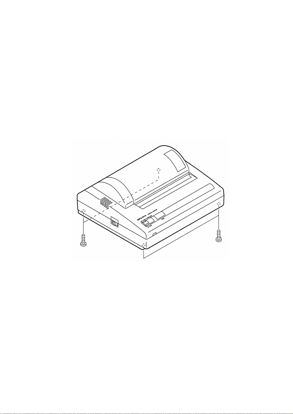
How to disassembly the DPU-414 Serial Thermal Printer is given in this chapter.
Procedure:
1. Remove the 4 screws in the bottom of the printer.
2. Lift the upper cover straight up to remove.
Figure 2-1 Remaining the Screws of the Upper Cover
2-1
Page 10

2-2
Page 11
CHAPTER 3
ADJUSTMENT
How to adjust the applied
given in this
chapter.
energy for the thermal head and the charging time for the battery are
3.1 ADJUSTING THE APPLIED ENERGY FOR THE THERMAL HEAD
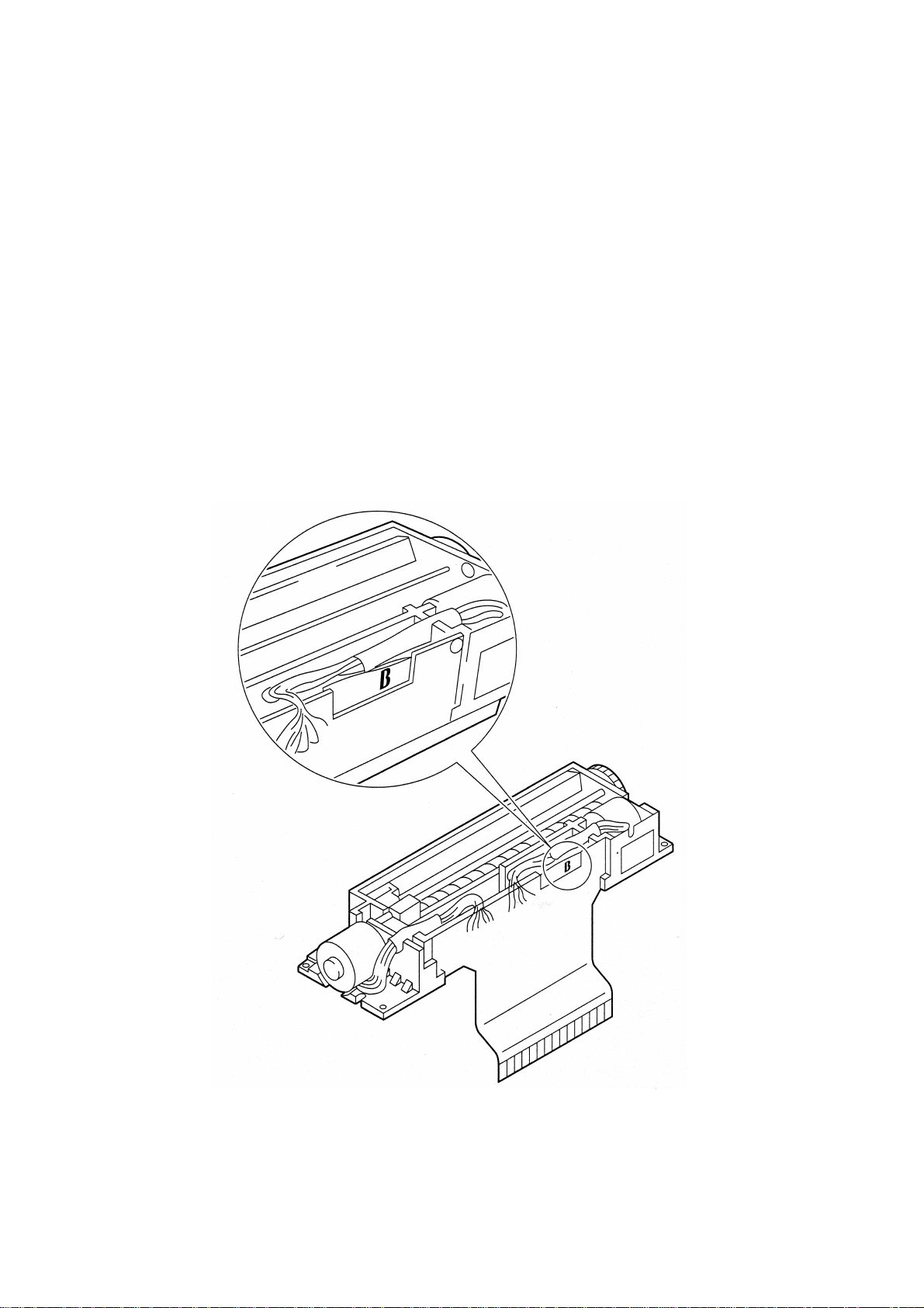
Procedure:
1. Check the head rank mark (A, B or C) displayed on the FPC of the printer mechanism
Figure 3-1 Head Rank Mark
3-1
Page 12

2. Initialize the dipswitches with the following procedure:
1. Remove the AC adapter from the power plug.
2. Connect the AC adapter to the power plug.
3. Power ON the printer while pressing the ONLINE and PAPER FEED buttons on the printer.
4. Release the ONLINE and PAPER FEED buttons after the ONLINE and OFFLINE Iamps blink.
It takes approx. 30 seconds.
3. Initialize the applied energy for the thermal head with the following procedure:
1. Prepare a parallel interface communication between the printer and the computer.
2. Send the following command from the computer:
ESC + "!" + FF
+ FF16
16
4. Set the head rank and the dipswitches with the following procedure:
1. Prepare a parallel interface communication between the printer and the computer.
2. 2. Send one of the following commands from the computer according to the head rank used:
Head rank
A ESC + "." + EB
B ESC + "." + EB
C ESC + ". " + EB
Command
+ FF16+ FF16+ 7316
16
+ FF16+ FF16+ 7216
16
+ FF16+ FF16+ 7116
16
5. Make sure that the printing density is OK by printing a test print.
3-2
Page 13

[Reference:]
Head Pulse Width:
[Condition:]
CAPTER 3 ADJUSTMENT
• 2-2 phase
• High speed print mode
• Print density: 100%
• Non-s im ulatio n of st rage he at
=Th
R×7.1
2
)25.0-Vp(
T-24
×2.1+1(×
op
10
Th: Head pulse width (ms)
Vp: Head applied voltage (V)
R: Head resistance (Ω)
Head rank
Resistance
A 17.9
B 16.3
C 14.7
Top: Ambient temperature (°C)
M: Correction factor according to the number of common activated dots
Number of dots
m
0 to 3 1.000
4 to 6 1.125
7 to 9 1.250
n: Correction factor according to the activation history
n×m×)
Activation history
000 7 / 7
100 6 / 7
010 5 / 7
110 5 / 7
001 4 / 7
101 4 / 7
011 4 / 7
111 4 / 7
n
3-3
Page 14

3.2 ADJUSTING THE CHARGING TIME FOR THE BATTERY
Procedure:
1. Initialize the dipswitches with the following procedure:
1. Remove the AC adapter from the power plug.
2. 2. Connect the AC adapter to the power plug.
3. Power ON the printer during pressing ONLINE and PAPER FEED button on the printer.
4. Relea se ONLINE and PAPER FEED buttons after the ONLINE and OFFLINE lamps blink. It
takes approx. 30 seconds.
2. Initialize the charging time for the battery with the following procedure:
1. Prepare a parallel interface communication between the printer and the computer.
2. Send the following command from the computer:
ESC + "#" + FF
3. Set the head rank and the dipswitches with the following procedure:
1. Prepare a parallel interface communication between the printer and the computer.
2. Send one of the following commands according to the head rank used from the computer:
16
Head rank
Command
A ESC + "." + EB
B ESC + "." + EB
C ESC + "." + EB
+ FF16 + FF16 + 7316
16
+ FF16 + FF16 + 7216
16
+ FF16 + FF16 + 7116
16
3-4
Page 15

CHAPTER 4
TROUBLESHOOTING
In this chapter, possible causes, the method for the ir diagnosis, and suggested recovery procedures for
problems that may occur when using the DPU-414 Serial thermal Printer are given.
Below is a listing of the items covered in this chapter, along with the number of the page where they can
be found.
No. Problem Page number
(1) No power. (with the AC adapter) 4-2
(1’) No power. (without the AC adapter) 4-2
(2) Battery is not charged. 4-2
(3) No interface Communication. 4-3
(4) Paper can not be fed. 4-3
(5) Abnormal sound is emitted. 4-3
(6) ERROR LED lights. 4-4
(7) The printer is not initialized. 4-4
(8) Nothing is printed. 4-4
(9) Dots are missing. 4-5
(10) Shortened printing in horizontal direction. 4-5
(11) Defective printing density. 4-5
(12) Uneven printing 4-6
(13) Shortened paper feed pitch. 4-6
4-1
Page 16

(1) No power. (with the AC adapter)
[Condition] The printer operates, but LEDs do not lights.
Possible cause Diagnostic method
Flat ribbon cable
disconnected
Defective soldering for LED or
defective LED
Defective mainboard
Check the continuity of the flat ribbon cable
with a tester.
Check the continuity of the LED with a
tester.
Measure the voltage of the LED with a
tester.
[Condition] The printer does not operate.
Possible cause Diagnostic method
AC adapter disconnected Measure the output voltage with a tester. 8.5 ± 2.0V Replace the AC adapter.
Defective main board
Measure the system clock for the main
board with an oscilloscope.
(1') No power. (without the AC adapter)
[Condition] The printer does not operate.
Possible cause Diagnostic method
The battery is not charged
Disconnected connector
Measure the output voltage of the battery
with a tester.
Visually inspect the connection of the
connector.
(2) Battery is not charged.
[Condition] The charging time is too short or long.
Judgement
and rating
Short Replace the flat ribbon cable.
Diode resistance Replace the switch board.
2.0 ± 0.5 V Replace the main board.
Judgement
and rating
4.19 MHz Replace the main board.
Judgement
and rating
5.6 ± 1.2V
Charge the battery with the
AC adapter.
-
Insert the connector
correctly.
Recovery
Recovery
Recovery
Possible cause Diagnostic method
Charging time setting error Measure the charging time.
Judgement
and rating
Approx. 10
hours
Set the charging time
correctly.
Recovery
[Condition] The charge of the battery is not started.
Possible cause Diagnostic method
Defective voltage of the
battery
Defective AC adapter
Measure the output voltage of the battery
with a tester.
Measure the output voltage of the AC
adapter with a tester.
Judgement
and rating
0.5 to 6.8 V Replace the battery pack.
8.5 ± 2.0 V Replace the AC adapter.
Recovery
4-2
Page 17

(3) No interface communication.
[Condition] The parallel communication does not operate.
CHAPTER 4 TROUBLESHOOTING
Possible cause Diagnostic method
Dipswitch setting error
Defective main board
Check the setting of the dipswitch
through the test print.
Check the l/O signals with an
oscilloscope.
[Condition] The serial communication does not operate.
Possible cause Diagnostic method
Dipswitch setting error
Defective main board Check the l/O signals with an oscilloscope. - Replace the main board.
Check the setting of the dipswitch through
the test print.
(4) Paper can not be fed.
[Condition] The paper feed motor does not operate.
Possible cause Diagnostic method
Defective drive voltage of the
paper feed motor
Attachment of alien
substances to the gears of the
paper feed motor
Measure the voltage between motor
common and each phase with an
oscilloscope.
Visually inspect for substances around the
gears.
(5) Abnormal sound is emmited.
[Condition] There is an abnormal sound when the thermal head is scanned.
Judgement
and rating
-
- Replace the main board.
Judgement
and rating
- Set the dipswitch correctly.
Judgement
and rating
4.88 ± 0.5 V Replace the main board.
- Remove alien substances.
Set the dipswitch
correctly.
Recovery
Recovery
Recovery
Possible cause Diagnostic method
Attachment of alien
substances around the head
carrier
Awry FPC for head
Visually inspect around the head carrier for
alien substances.
Visually inspect the FPC for head for alien
substances.
Judgement
and rating
- Remove alien substances.
- Set the FPC correctly.
Recovery
[Condition] There is an abnormal sound when the paper is fed.
Possible cause Diagnostic method
Attachment of alien
substances to gears
concerned with the paper feed
Visually inspect the gear around for alien
substances.
4-3
Judgement
and rating
- Remove alien substances.
Recovery
Page 18

(6) ERROR LED Iights.
[Condition] The printer does not operate.
Possible cause Diagnostic method
Paper jams and the head does
not scan
Visually inspect the paper jam. - Remove the paper jam.
(7) The printer is not initialized.
[Condition] The head scaning motor starts and stop immediately.
Possible cause Diagnostic method
Defective timing switch
Check ON/OFF of the home switch with a
tester.
(8) Nothing is printed.
[Condition] The head operates correctly, but nothing is printed.
Possible cause Diagnostic method
Disconnected FPC for the head
Disconnection of the connector
of the FPC for the head
Burned thermal head
Reverse setting of the thermal
paper
Paper used is not a thermal
paper
Measure the resistance of the FPC for the
head with a tester.
Visually inspect the connection of the FPC
connector.
Measure the resistance of the FPC for the
head with a tester.
Visually inspect the surface of the thermal
paper.
Visually inspect the paper itself. -
[Condition] The printer does not operate.
Judgement
and rating
Judgement
and rating
- Replace the printer unit.
Judgement
and rating
16.3 ±: 3.0 Ω Replace the printer unit.
- Insert the connector correctly.
16.3 ± 3.0 Ω Replace the printer unit.
-
Set the thermal paper
correctly.
Use the specified thermal
paper.
Recovery
Recovery
Recover y
Possible cause Diagnostic method
Disconnection of the connector
of the head scaning motor
Disconnected load wire for the
head scaning motor
Defective main board
Visually inspect the connection of the head
scanning motor connector.
Check the continuity of the lead wire. Short Replace the printer unit.
Measure the drive voltage of the head
scaning motor with an oscilloscope.
Judgement
and rating
4.88 ±: 0.5 V Replace the main board.
- Insert the connector correctly.
Recovery
4-4
Page 19

(9) Dots are missing.
[Condition] Only certain dots are not printed.
CHAPTER 4 TROUBLESHOOTING
Possible cause Diagnostic method
Disconnected FPC for the
head
Defective contact between the
FPC for the head and the
connector on the board
Burned thermal head
Measure the resistance of the FPC for the
head with a tester.
Measure the resistance of the connector on
the board with a tester. 16.3 ± 3.0 Ω
Measure the resistance of the FPC for the
head with a tester.
(10) Shortened printing in horizontal direction.
[Condition] Stack of dots.
Possible cause Diagnostic method
Step-out of the head scaning
motor (Abnormality of the drive
voltage of the head scaning
motor)
Step-out of the head scaning
motor (Attachment of alien
substances around the head
carrier)
Measure the voltage between motor
common and each phase with an
oscilloscope.
Visually check alien substances around the
head carrier.
(11) Defective printing density.
[Condition] All dots are blurred or too light
Judgement
and rating
16.3 ± 3.0 Ω
16.3 ±: 3.0 Ω
Judgement
and rating
4.88 ± 0.5 V
-
Recovery
Replace the printer unit.
Insert the FPC to the
connector correctly again.
Replace the printer unit.
Replace the main board.
Remove alien substances.
Recovery
Possible cause Diagnostic method
Defective thermal head
resistance
Defective contact between the
FPC and the connector
Use of unspecified paper Visually inspect the paper used.
Error of the dipswitch setting
Error of the head rank or
applied energy setting
Measure the resistance at the FPC
terminals with a tester.
Measure the resistance at the connector
terminals with a tester.
Execute the test print and check the
printing density.
Measure the applied pulse width and
voltage with an oscilloscope.
Judgement
and rating
16.3 ± 3.0 Ω
16.3 ± 3.0 Ω
-
-
-
Replace the printer unit.
Insert the FPC to the
connector correctly again .
Use the recommended
thermal paper.
Set the dipswitch correctly.
Adjust the applied pulse
width correctly.
Recovery
4-5
Page 20

[Condition] Certain dots are blurred or too light.
Possible cause Diagnostic method
Flaw and dent of the platen
surface
Defective rocking of the platen Visually inspect alien substances around
Increase of the resistance of the
certain dots of the thermal head
Attachment of alien
substances to the platen
Visually inspect the surface of the platen
(rubber of the platen).
the platen supporter.
Measure the resistance at the FPC
terminals with a tester.
Visually inspect the surface of the platen
(rubber of the platen).
(12) Uneven printing.
[Condition] The start point of printing is uneven.
Possible cause Diagnostic method
Step-out of the head scaning
(out of range of printing)
(Defective drive voltage of the
head scaning motor)
Step-out of the head scaning
motor
(out of range of printing)
(Attachment of alien substances
around the head carrier)
Defective timing switch Check the switch timing with an
Measure the voltage between motor
common and each phase with an
oscilloscope.
Visually inspect alien substances around
the head carrier.
oscilloscope.
(13) Shortened paper feed switch.
[Condition] There is a stack of the line space.
Judgement
and rating
-
-
16.3 ± 3.0 Ω
-
Judgement
and rating
4.88 ± 0.5 V
-
-
Recovery
Replace the printer unit.
Remove alien substances
with a cotton swab.
Replace the printer unit.
Remove alien substances
with a cotton swab.
Replace the main board.
Remove alien substances.
Replace the printer unit.
Recovery
Possible cause Diagnostic method
Step-out of the paper feed
motor
(Defective drive voltage of
Measure the voltage between motor
common and each phase with an
oscilloscope.
Judgement
and rating
4.88 ± 0.5 V
Recovery
Replace the main board.
the paper feed motor)
Step-out of the paper feed
motor (Attachment of alien
substances to gears
Visually inspect around the gears.
-
Remove alien
substances.
concerned with the paper
feed)
Too much paper load
Visually inspect the set condition of
the paper.
-
Set the paper correctly
again.
4-6
Page 21

CHAPTER 5
CIRCUIT DIAGRAM
Diagrams of the circuit board are given in this chapter.
5-1
Page 22

5.1 MAIN BOARD CIRCUIT DIAGRAM
2SA1931
S-812C52AUA
NV73A1JTTE20
Figure 5-1 Main Board Circuit Diagram (1/3)
5-2
Page 23

CHAPTER 5 CIRCUIT DIAGRAM
S-808
uPD780053GC
S-93C46BD0I
36CNUA
NJL5165KB
Figure 5-2 Main Board Circuit diagram (2/3)
5-3
Page 24

uPD780053GC
22-02-3253
Figure 5-3 Main Board Circuit Diagram (3/3)
5-4
Page 25

5.2 SWITCH BOARD CIRCUIT DIAGRAM
PG7351KY
CHAPTER 5 CIRCUIT DIAGRAM
Figure 5-4 Switch Board Circuit Diagram
5-5
Page 26

5-6
Page 27

CHAPTER 6
BOARD DIMENSIONS
Dimensions of the board are given in this chapter.
6-1
Page 28

6.1 MAIN BOARD DIMENSION
4.26 (108.4)
6.06 (154)
Figure 6-1 Main Board Wiring Pattern (Heads side)
6.06 (154)
Figure 6-2 Main Board Wiring Pattern (Tails side)
Unit: inches (mm)
6-2
Page 29

CHAPTER 6 BOARD DIMENSIONS
Figure 6-3 Main Board Parts Layout (Heads side)
Figure 6-4 Main Board Parts Layout (Tails side)
6-3
Page 30

6.2 SWITCH BOARD DIMENSION
2.36 (60)
0.94 (24)
Figure 6-5 Switch Board Dimensions
6-4
Unit: inches (mm)
Page 31

CHAPTER 7
PARTS LIST
Diagrams and list of the DPU-414 Serial thermal Printer parts are given in this chapter.
7-1
Page 32

Figure 7-1 Parts Developments
7-2
Page 33

CHAPTER 7 PARTS LIST
Table 7-1 Parts List
No. Part No. Part name Qty. Comments
U000092913X3
1
2
3
4
5
6
7
8
9
10
11
U000093374X2
U000952806X0
U000955855X0
U000955866X0
U000094421X1
U000093600X1
U000095038X0
U000095084X0
U000094948X0
U000076116X0
UPPER CASE 1 With paper cutter
BOTTOM CASE 1 With rubber foot
PRINTER MECHANISM BLOCK 1
MAIN PCB BLOCK 1 With ribbon wire
SWITCH PCB BLOCK 1
PAPER COVER 1
BATTERY LID 1
POWER SW SLIDER 1
ALTERNATE SW BUTTON 1
FEED BUTTON 1
GROUNDING TERMINAL A 1
U00009793100
12
U00099961700
13
U00095504500
14
U00009794200
15
U00009803200
16
Pan head tap tight screw (B tight),NIP,
2.0 x 6
Pan head tap tight screw (B tight) ,NIP,
2.6 x 18
Pan head tap tight screw (B tight) ,NIP,
3.0 x 6
Pan head tap tight screw (B tight) ,NIP,
3.0 x 10
Sems screw (T) ,NIP,
M3.0 x 8
For attaching PRINTER
4
MECHANISM BLOCK
For attaching UPPER
4
CASE and BOTTOM
CASE
For attaching MAIN PCB
BLOCK and SWITCH PCB
3
BLOCK
For attaching
GROUNDING TERMINAL
1
A
1 For attaching terminal
7-3
Page 34

7-4
Page 35

CHAPTER 8
PACKING SPECIFICATIONS
The packing list and diagrams for the DPU-414 Serial Thermal Printer are given in this chapter.
8-1
Page 36

1
3 (cushion)
2
3 (vinyl bag)
Figure 8-1 Packing Materials developments
3 (inner box)
3 (outer box)
8-2
Page 37

CHAPTER 8 PACKING SPECIFICATIONS
Table 8-1 Packing List
No. Part No. Part name Qty. Comments
1
2
3
U000448558X6
U000765854X0
U000086185X0
USER'S GUIDE
THERMAL ROLL PAPER 1
Individual Packing Box Set 1
1
Outer box, inner box,
cushion and vinyl bag
8-3
 Loading...