

Page 1

DPU-30
THERMAL PRINTER
TECHNICAL REFERENCE
U00084936302
Seiko Instruments Inc.
Page 2

DPU-30 TECHNICAL REFERENCE
Document Number U00084936302
First Edition January 2004
Second Edition
Third Edition March 2006
Seiko Instruments Inc. (SII) has prepared this manual for use by SII personnel, licensees, and
customers. The information contained herein is the property of SII and shall not be reproduced in
whole or in part without the prior written approval of SII.
November 2005
Copyright
©2004, 2005, 2006 by Seiko Instruments Inc.
All rights reserved.
SII reserves the right to make changes without notice to the specifications and materials contained
herein and shall not be responsible for any damages (including consequential) caused by reliance
on the materials presented, including but not limited to typographical, arithmetic, or listing errors.
SII is a trademark of Seiko Instruments Inc.
ESC/POS is a trademark of EPSON.
Page 3

Introduction
DPU-30-0B-E is a compact printer unit which is connected to a computer or a host system via a
parallel port (Centronics interface) or serial port (RS-232C) and prints the data input through such
interface in the direct thermal printing.
Features of this printer
• Provides the High-speed and noiseless print according to thermal printing system.
• Because of the direct thermal printing, this printer is very quiet while printing.
• Prints both 16×16 and 24×24 dot size characters clearly.
• Prints the Kanji characters (JIS level 1 non-kanji, level 1 and 2).
• Prints barcodes using the barcode print function. (UPC-E, JAN13, JAN8, CODE39, ITF,
CODABAR, and CODE128).
• Test patterns can be printed.
• Prints the test pattern and dump mode characters.
• Print the various size characters such as enlargement character.
Standard size character
Kanji size character
Enlargement characters (64 times characters size max)
• Defines the line spacing and character spacing arbitrarily.
• Prints the various size characters such as enlargement character.
• Prints the graphic using the Bitimage.
• Registers and prints any font using the downloaded character function and user-defined
character function.
• Feeds paper forward or backward using the paper feed functions.
• Characters to be printed can be inverted from black-on-white to white-on black, or vice versa.
• Characters to be printed can be flipped from top to bottom.
• Provides various functions including the reverse printing, flip or ruler line.
• Changes the print density using print density command.
• ESC/POS compliant command system is adopted.
Structure of this printer
• This printer is compact and thin so that it takes less space than the others.
• Its design is simple so that it can be used with any type of devices.
Functions
• The out-of-paper detection sensor is mounted on this printer.
• The easy-to-use operation function allows to easily replenish paper.
Power supply
• The power is fed via a connector for interface.
Page 4

Page 5

TABLE OF CONTENTS
Section Page
CHAPTER 1 OPERATIONAL PRECAUTION
1.1 SAFETY PRECAUTION............................................................................................... 1-1
1.2 NOTES ON USE .......................................................................................................... 1-2
1.3 NOTES ON TREATMENT OF THERMAL PAPERS.................................................... 1-3
1.4 NOTES ON INSTALLATION........................................................................................ 1-3
CHAPTER 2 TERMS USED IN THIS MANUAL
CHAPTER 3 PREPARATIONS AND OPERATION
3.1 PARTS NAME .............................................................................................................. 3-1
3.2 DIMENSIONS............................................................................................................... 3-2
3.3 INSTALLATION............................................................................................................ 3-4
3.4 SETTINGS OF THE FUNCTIONS............................................................................... 3-6
3.4.1 Test Print..................................................................................................... 3-7
3.4.2 Hex Dump Print........................................................................................... 3-7
3.4.3 Paper Empty (Paper Out) Detection Function............................................. 3-7
3.4.4 Adjustment of Print Density......................................................................... 3-7
3.4.5 Resetting the Printer While Printing ............................................................ 3-8
3.4.6 Memory ....................................................................................................... 3-8
CHAPTER 4 INTERFACE
4.1 CONNECTOR TERMINAL LAYOUT............................................................................ 4-1
4.2 PARALLEL INTERFACE.............................................................................................. 4-3
4.3 SERIAL INTERFACE ................................................................................................... 4-3
CHAPTER 5 COMMAND FUNCTION
5.1 FUNCTION OUTLINE .................................................................................................. 5-1
5.1.1 Mode 1/Mode 2 ........................................................................................... 5-1
5.1.2 Mode 3 ........................................................................................................ 5-2
Page 6

Section Page
5.2 FUNCTION CODES..................................................................................................... 5-5
5.3 CHARACTER CODES................................................................................................. 5-5
5.3.1 1-Byte Character Codes ............................................................................. 5-5
5.3.2 2-Byte Character Codes ............................................................................. 5-5
5.4 FUNCTION CODE DESCRIPTION.............................................................................. 5-6
5.4.1 Function Code Description Format............................................................. 5-6
5.4.2 Mode 1/Mode 2........................................................................................... 5-7
5.4.3 Mode 3........................................................................................................ 5-12
APPENDICES
APPENDIX A. SPECIFICAIONS ............................................................................................ A-1
APPENDIX B. DATA CODE TABLE....................................................................................... B-1
Page 7

FIGURES
Figure Page
2-1 System Configuration.................................................................................................... 2-1
3-1 Front Name of the Printer ............................................................................................. 3-1
3-2 Back Name of the Printer.............................................................................................. 3-1
3-3 Printer Dimensions ....................................................................................................... 3-2
3-4 Fixing Bracket Dimensions ........................................................................................... 3-3
3-5 Installing the Fixing Bracket.......................................................................................... 3-4
3-6 Setting Paper................................................................................................................ 3-5
Page 8

TABLES
Table Page
3-1 DIP Switch Setting........................................................................................................ 3-6
3-2 Communication Method ............................................................................................... 3-6
3-3 Command Mode........................................................................................................... 3-6
4-1 Connector Terminal Assignment.................................................................................. 4-1
4-2 DC Socket Terminal Assignment ................................................................................. 4-2
4-3 I/O Signal Specifications............................................................................................... 4-5
5-1 Status Response Value Table...................................................................................... 5-35
Page 9
CHAPTER 1
OPERATIONAL PRECAUTION
1.1 SAFETY PRECAUTION
Meanings of symbols
The following symbols are used in this Instruction Manual in order to make use of the printer
properly and prevent the printer from being damaged.
Follow the instructions marked with the symbol.
WARNING
CAUTION
Symbol Examples
The symbol indicates caution(including danger and warning).
The example on the left indicates warning or caution.
The symbol indicates prohibition.
The example on the left means prohibition of disassembling.
Do not use a power supply outside of its specified range.
Doing so may cause fire leading to serious accidents.
Do not forcefully bend, or put a heavy matter on, the power cable. Failure to
follow this instruction may damage the power cable, which may result in a fire
or electric shock. Do not use the power cable if it is damaged.
Failure to follow the guidelines marked with this symbol could
result in severe personal injury or death.
Failure to follow the guidelines marked with this symbol could
result in minor personal injury or product and/or peripheral
damage.
WARNING
Never disassemble the printer. Failure to follow this instruction may cause
overheating or burning of the printer which may lead to fires or accidents.
1-1
Page 10
CAUTION
Do not drop any metallic objects or liquids such as water or coffee into the
printer.
Never use the printer in a place of extreme humidity or any place where it
can possibly be splashed by any liquids. If any liquids get into the printer, it
could lead to fire, electric shock, or other serious accidents.
Never touch the thermal head immediately after printing because it
becomes very hot. Make sure that the thermal head is cool before setting
papers or cleaning the thermal head.
Be sure to hold the connector part of the power cable when disconnecting
the cable. Pulling on the cable portion may cause it to fray and break.
Power OFF the printer in any of the following cases:
•
•
•
printer.
Using the printer in any manner other than for which it was designed may
cause accidents or fire.
The printer does not recover from an error.
Smoke, strange noise or smells erupt from the printer.
A piece of metal or any liquid touches the internal parts or slot of the
1.2 NOTES ON USE
• Do not disassemble or repair the printer by yourself.
• Do not drop the printer down on the floor or hit it against the walls.
• Avoid exposure to the water.
• Use the specified type of thermal paper.
• When a trouble such as a paper jam occurs, turn off the power first to fix it.
• The printer does not receive the data in some cases such as a paper out. Monitor the printer
to check if an error occurs and not to stop the system.
• Fix an error if something happens to the printer in order to prevent the whole system from
hanging up. Thus, you need to take an action to prevent the error from affecting the whole
system.
• Immediately turn off the power if the printer fails (for example, you smell something strange,
hear a noise, or smoke rises from the printer). After checking that such failure does not
continue, contact your dealer or us.
1-2
Page 11

1.3 NOTES ON TREATMENT OF THERMAL PAPERS
The surface of thermal paper is specially processed using the chemical agent. And the color rises
through the thermo chemical reaction process. Be aware of the following points.
1) Store the papers in a dry, cool and dark place.
2) Do not rub the papers with hard substance.
3) Keep the papers away from organic solvent.
4) Do not let the papers touched with vinyl chloride film, eraser or adhesive tapes for hours.
5) Do not put the papers on diazo print or wet copy that is just copied
6) Use the water-based glue (for example, starch glue and synthetic glue) when you glue
thermal paper.
7) Adhesive tape may discolor the surface of thermal paper. Put two-sided tape on the back
side of thermal paper if you need to tape it.
8) If you touch thermal paper with sweaty hand, your fingerprint may be left on the surface of
thermal paper and the characters may printed unclearly.
9) If you use this printer to print receipts given to your customers, print the notice which states
that the paper used is thermal paper and the instructions on how to keep it.
10) Use dedicated thermal papers only.
1.4 NOTES ON INSTALLATION
Avoid such places with:
1) Dusty places
2) Unstable places and places that significantly shakes
3) Watery and oily places
4) Places which receive direct sunlight
5) Places where the temperature is 50°C or higher
6) Places where the temperature is 0°C or lower
7) Places where the electromagnetic interference or corrosive gas is generated
8) Places where the relative humidity is over 80%
9) Places where the significant temperature change may result in the formation of any
condensation
1-3
Page 12

1-4
Page 13
Li
CHAPTER 2
TERMS USED IN THIS MANUAL
This chapter describes the terms used in this manual.
Dot A character or graphic im age is c om posed of picture elem ents called dots.
A dot corresponds to one of the thermal head heat elements.
Dot line A line of dots arranged perpendicular to the paper feed direc tion. A dot
line corresponds to a line of thermal head heat elements.
One dot line consists of 384 dots in DPU-30.
Character spacing The space separating contiguous characters on one character line.
Line spacing The space separating character lines.
Input buffer The mem ory for temporarily storing the data (characters and commands)
received from the host device. Data is executed when fetched fr om the
input buffer. The capacity of the input buffer is 4,096 bytes.
Line buffer The memory for storing one line of char acter data fetched from the input
buffer. W hen the line buff er is f illed with character data (i.e. printing of an
entire line) or the printing conditions are m ade valid through a command,
the data in the input buffer is printed.
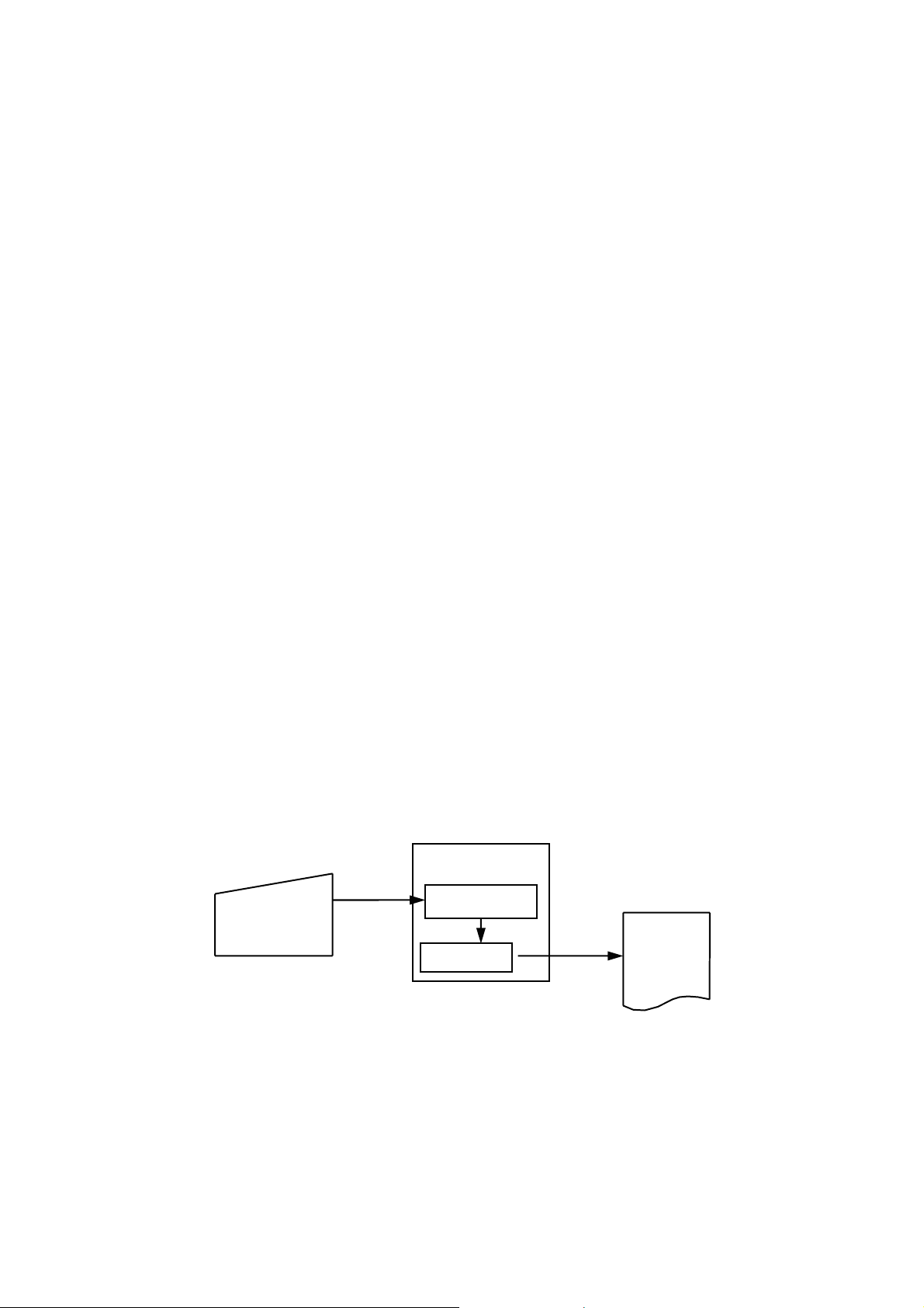
The system configuration is shown in Figure 2-1.
Host device
DPU-30
Input buffer
ne buffer
Printer
Figure 2-1 System Configuration
2-1
Page 14

One line full print The printing executed when the data in the line buffer ex ceeds one line.
Character data for one line is stored in the line buffer. When inflowing
data exceeds the number of characters that can be s tor ed in the line buf f er,
the data in the line buffer are printed. The overflowing data is stored at
the beginning of the next line.
Kanji size characters Kanji and user-defined characters.
Standard size Extended graphics characters, katakana, and downloaded characters.
characters
Font The form of a character. A character is composed of a group of dots.
The user can define a font using downloaded fonts, etc.
Font size The size of a character. There are two font sizes, 16-dot font size and
24-dot font size.
The sizes for standard size and Kanji size characters are shown below.
Each size is represented as vertical dots by horizontal dots.
16-dot (height × width)
Standard size characters 16 × 8 24 × 12
Kanji size characters 16 × 16 24 × 24
1-byte characters/ Classification by character codes.
2-byte characters Characters can be specified by 2 types of character codes: 1-byte
character codes and 2-byte character codes.
2-byte character is effective when the situation of kanji mode is specified.
Characters that can be specified by 1-byte character codes include:
• Alphabets, Numbers, and Katakana
• Extended graphics characters
• Downloaded characters
Characters that can be specified by 2-byte character codes include:
• Kanji
• User-defined characters
24-dot (height × width)
2-2
Page 15
CHAPTER 3
PREPARATIONS AND OPERATION
This section describes the information necessary to use the printer connecting to a host device such
as the part names and dimensions of the printer, and how to set the functions.
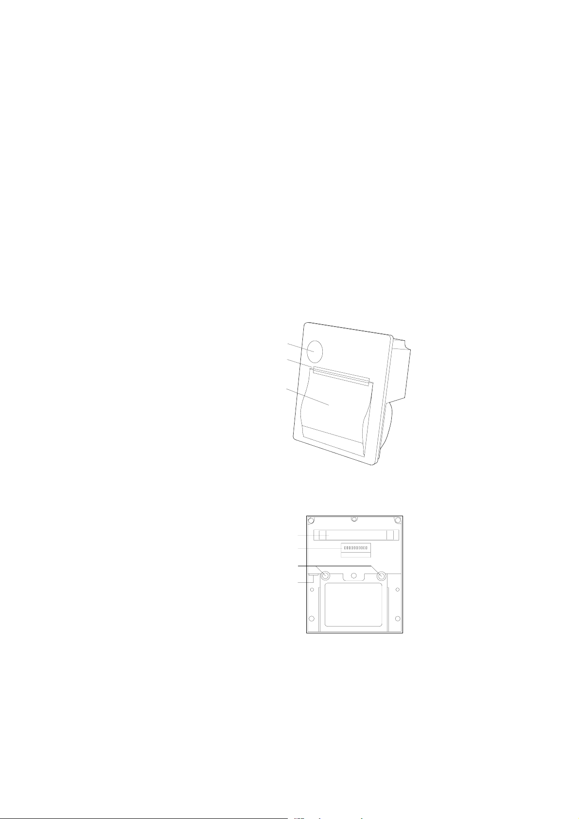
3.1 PARTS NAME
ペーパーカバーオープンボタン
Paper cover open button
ペーパーカッタ
Paper cutter
Paper cover
ペーパーカバー
Figure 3-1 Front Name of the Printer
インターフェース用コネクタ
固定金具用インサートナット
Interface Connector
Dip switches
ディップスイッチ
Insert nut for fitting
DC socket
DCソケット
ON
1
234567
890
Figure 3-2 Back Name of the Printer
3-1
Page 16
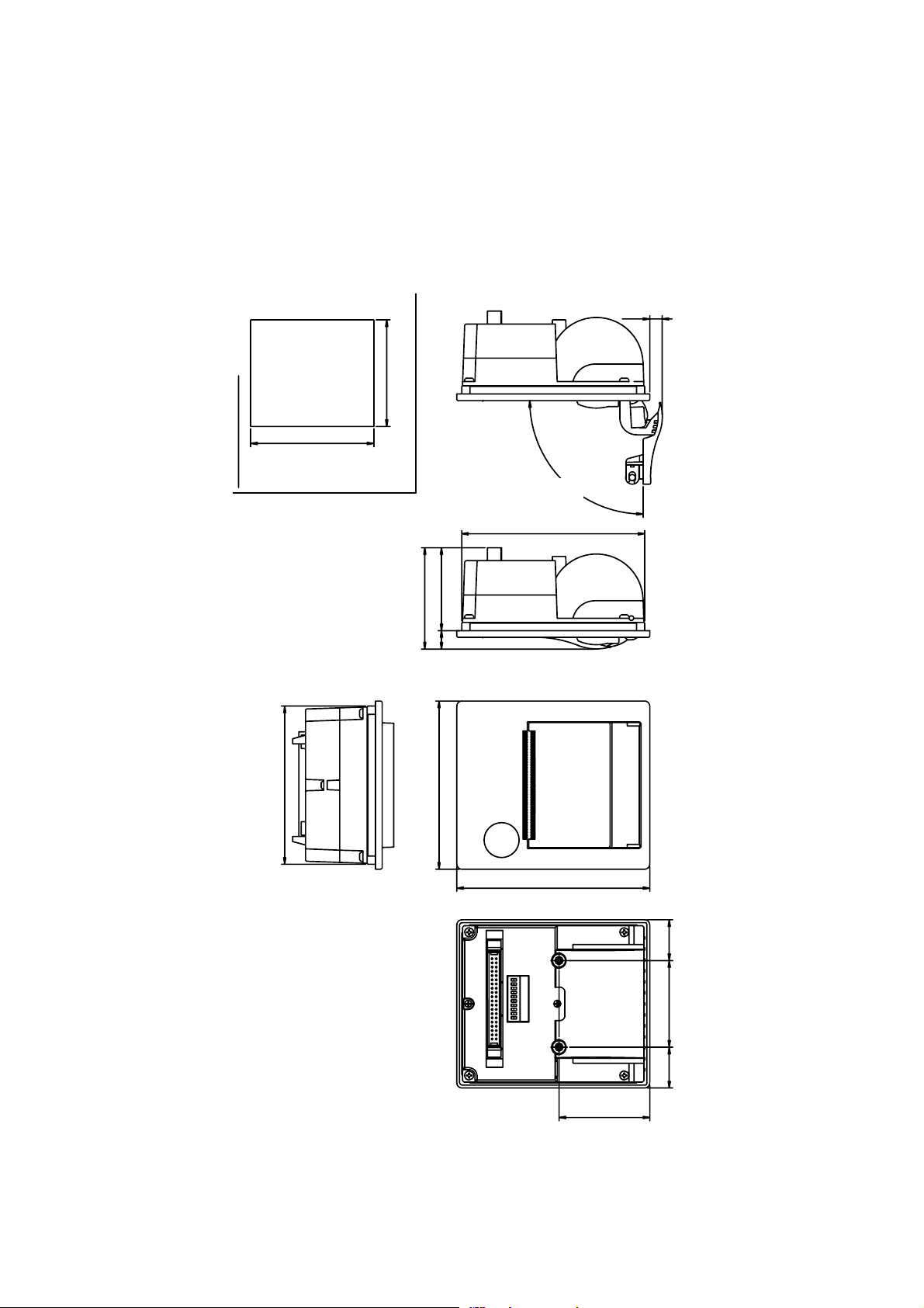
3.2 DIMENSIONS
1. Dimensions of the printer
111.2+0/-0.5
取り付け穴寸法図
Dimensions of the fitting hole
7.5
単位:mm
96+0/-0.5
°
0
約9
Approx. 90º
110
50
61
11
95
Figure 3-3 Printer Dimensions
101
3-2
116
54.5
24.5
52
(24.5)
Unit: mm
Page 17
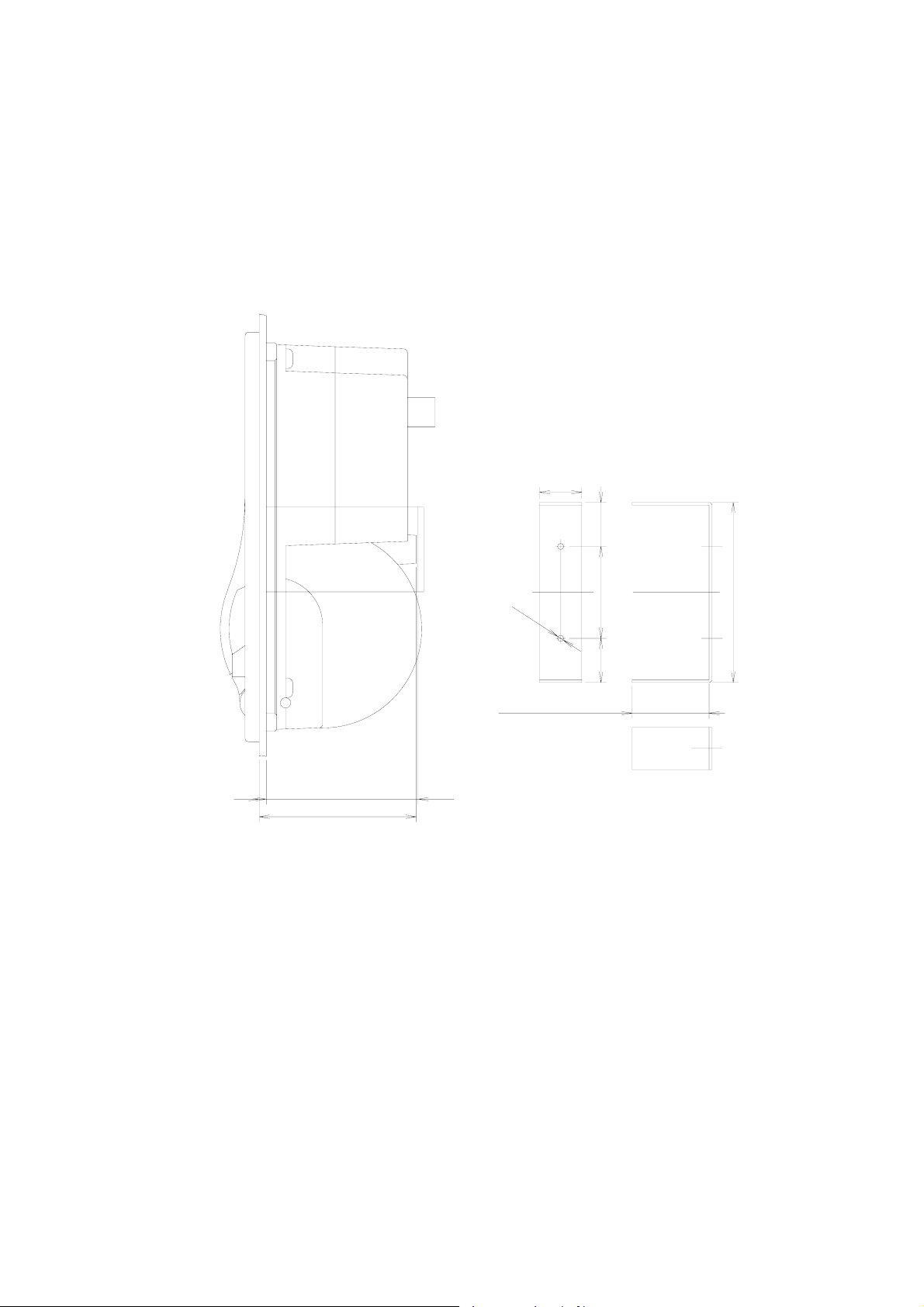
2. Dimensions of the fixing bracket
固定金具条件
固定金具参考図
24
24
(25)
(25)
2
-
φ
3
2- φ3.6
.
6
44.5 - Panel thickness + 0.5 ±0.3
45.5-板厚+0.5±0.3
52
5225
25
102
102
板厚
44.5 - Panel thickness + 0.5 ±0.2
44.5-板厚+0.5±0.2
44.5
44.5
単位:mm
Unit: mm
Panel thickness
Figure 3-4 Fixing Bracket Dimensions
3-3
Page 18
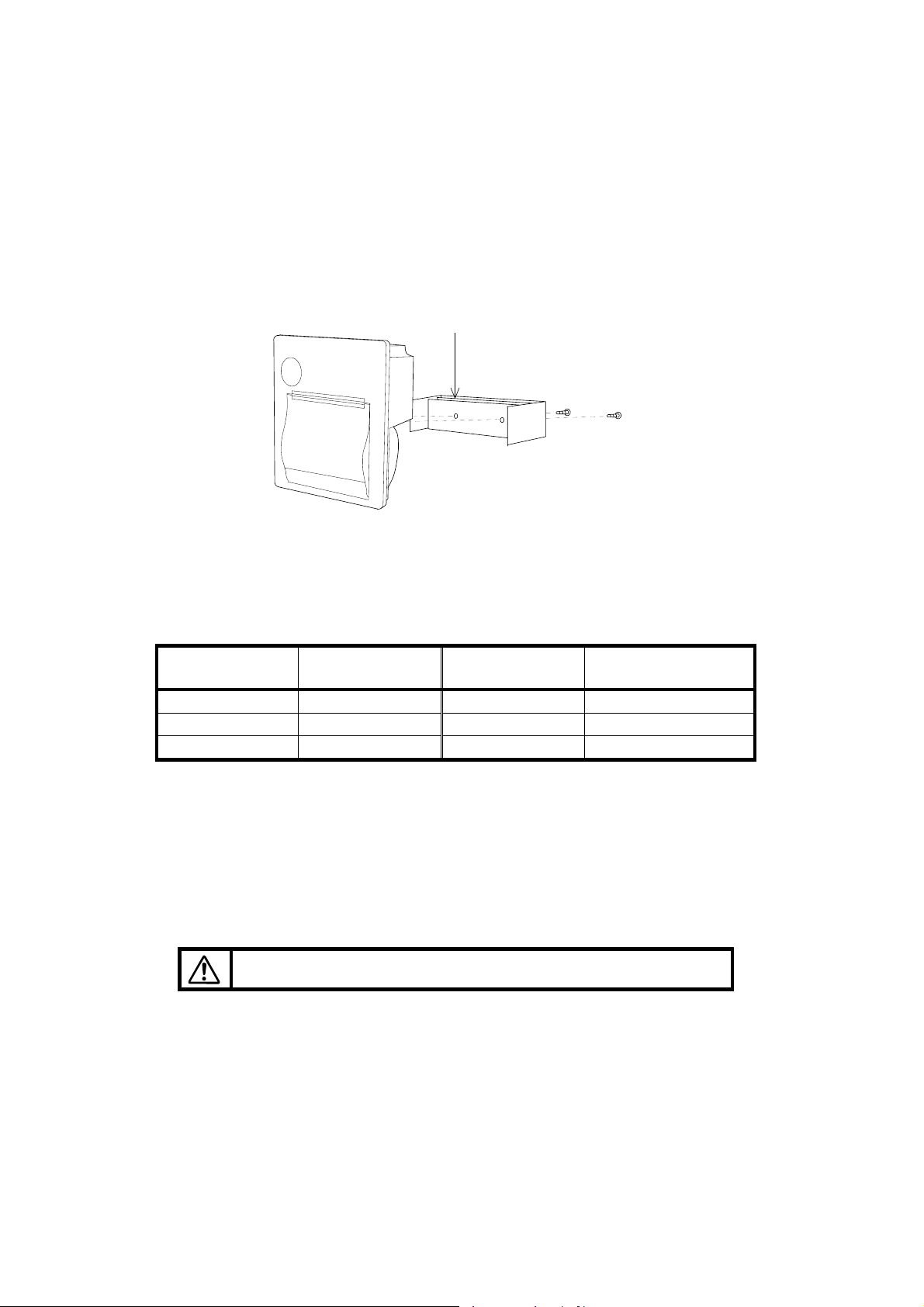
3.3 INSTALLATION
1. How to Install the Fixing Bracket
Use the spacers as much as you need
スペーサーを必要なぶん重ねて使用する。
Figure 3-5 Installing the Fixing Bracket
∗ Use the spacers depending on the fitting panel thickness referring to the next table. If not,
the body may be deformed, and therefore it may be hard to open the paper cover or printing
quality may be deteriorated. (If the fitting panel thickness exceeds 2.2 mm, it may be hard to
tighten the screws.)
Panel thickness
Spacer
thickness
Panel thickness Spacer thickness
1.0 mm None 1.7 to 1.8 mm 0.5 mm and 0.2 mm
1.2 mm 0.2 mm 2.0 mm 1.0 mm
1.5 to 1.6 mm 0.5 mm 2.2 mm 1.0 mm and 0.2 mm
∗ The screw torque is 49 cN m (5 kgf cm).
[Note] Do not touch the end of the DC plug.
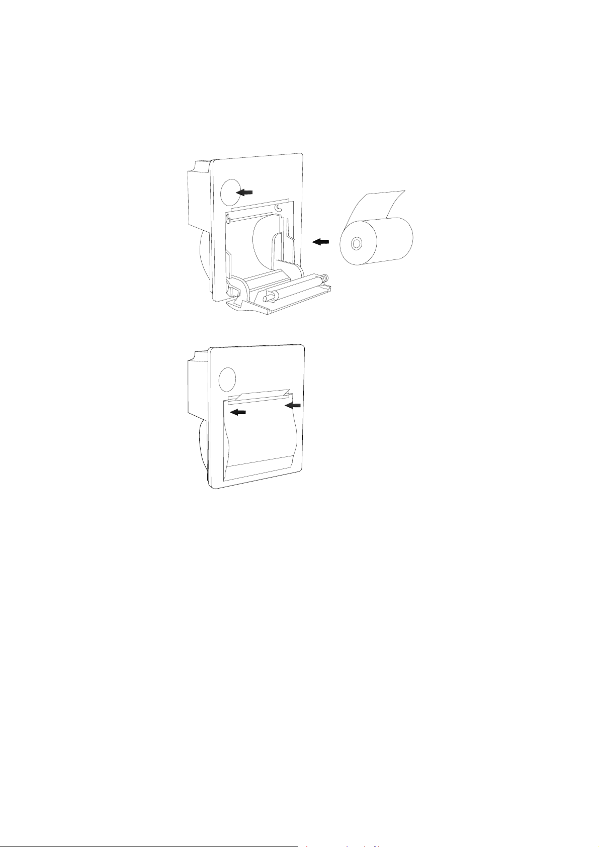
2. Setting Paper
(1) Press the paper cover open button, and open the paper cover.
Handle the paper cutter carefully not to cut your hand.
(2) Set a paper roll as shown in the figure.
(3) Close the paper cover by pressing both ends of the cover so the tip end of the paper will
be emerged from the printer.
3-4
Page 19
①
②
③
③
Figure 3-6 Setting Paper
3-5
Page 20
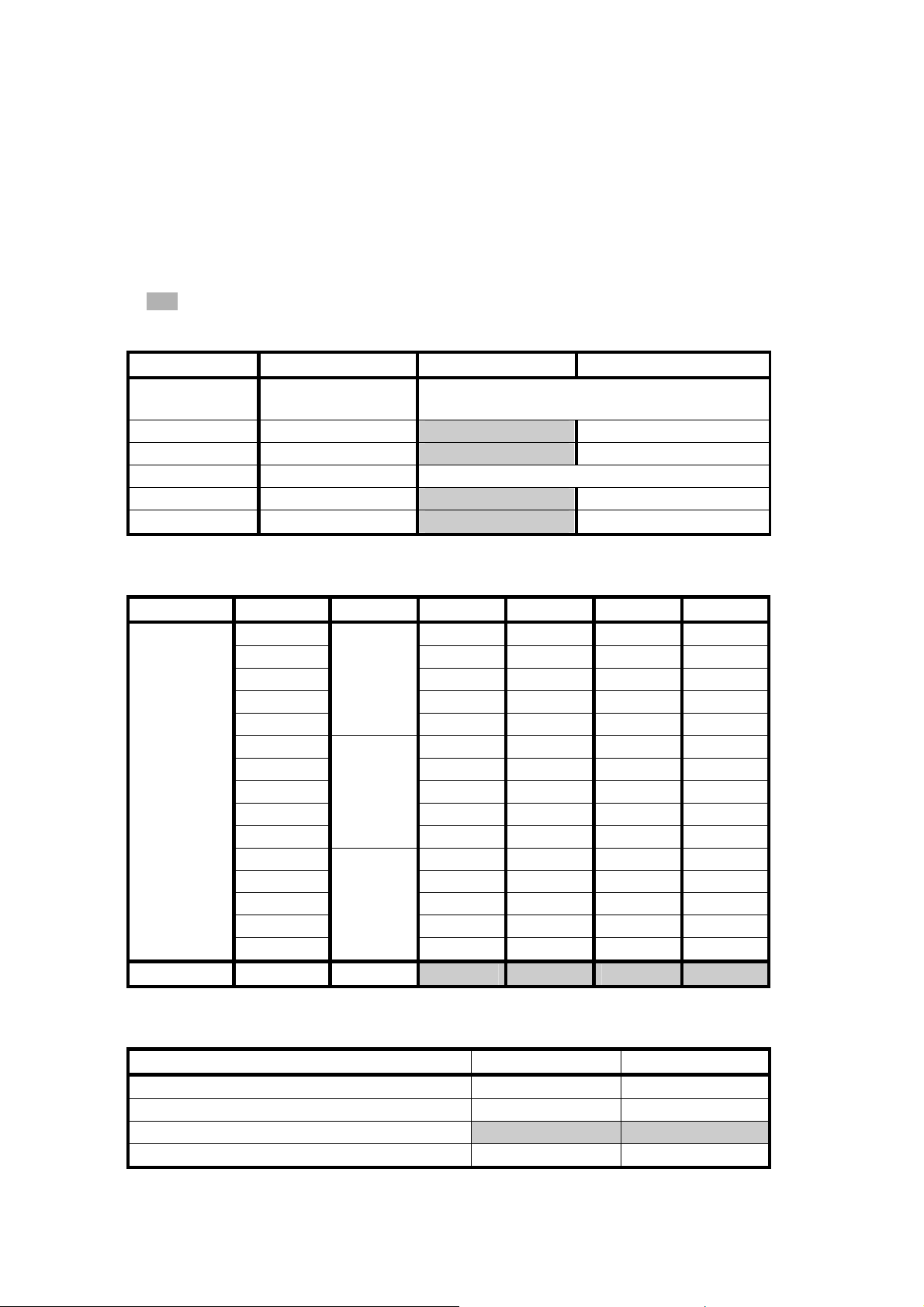
3.4 SETTINGS OF THE FUNCTIONS
Printer functions can be set with the dip switches.
The indicates the factory default setting.
Table 3-1 DIP Switch Setting
No Function OFF ON
1 to 4 Communication
See Table 3-2.
method
5 Bit length 8BIT 7BIT
6 Flow RTS/CTS Xon/Xoff
7 to 8 Command mode See Table 3-3.
9 Direction Upright Invert
0 Test pin Normal mode Prohibited
Table 3-2 Communication Method
Method Baud Parity DP1 DP2 DP3 DP4
Serial
38400 OFF OFF OFF OFF
None
19200 ON OFF OFF OFF
9600 OFF ON OFF OFF
4800 ON ON OFF OFF
2400
38400 ON OFF ON OFF
Odd
OFF OFF ON OFF
19200 OFF ON ON OFF
9600 ON ON ON OFF
4800 OFF OFF OFF ON
2400
38400 OFF ON OFF ON
Even
ON OFF OFF ON
19200 ON ON OFF ON
9600 OFF OFF ON ON
4800 ON OFF ON ON
2400
OFF ON ON ON
Parallel − − ON ON ON ON
Table 3-3 Command Mode
Mode DP7 DP8
Mode 1 (20 digit DPU-20-20CF compatible) ON ON
Mode 2 (24 digit DPU-20-24CF compatible) OFF ON
Mode 3 (32 digit ESC/POS compliant) OFF OFF
HEX dump mode ON OFF
3-6
Page 21

3.4.1 Test Print
The detail of the setting by dip switches is confirmed by test printing.
In the test print mode, characters (ANK, Kanji) and barcode are printed.
Turning power ON with the !FEED_IN signal kept low starts the test print.
3.4.2 Hex Dump Print
In the hex dump mode, the printer prints data input from the computer with hexadecimal numbers
and characters.
Set the dip switch No.7 ON, No.8 OFF, and turn the power on to enter the HEX dump mode.
• If the input data exceeds a line long, such data will be printed as follows. If the input data
does not exceeds a line log, set the !FEED_IN signal to Low. The rest of the data will be
printed.
• Turn off the power to finish the HEX dump mode.
[ HEX DUMP MODE ]
00 01 02 03 04 05 06 07 ........
08 09 0A 0B 0C 0D 0E 0F ........
10 11 12 13 14 15 16 17 ........
18 19 1A 1B 1C 1D 1E 1F
20 21 22 23 24 25 26 27
28 29 2A 2B 2C 2D 2E 2F ()∗+,-./
0D 0A 20 20 0D 0A
.. ..
........
!″ #$%&′
3.4.3 Paper Empty (Paper Out) Detection Function
Detects the existence of paper using the photo interrupter.
Use the specified type of paper.
3.4.4 Adjustment of Print Density
The print density is automatically adjusted by the head resistance, the number of dots, the head
temperature, and the head voltage.
The commands are also able to correct the print density.
It can be adjusted in the range from 0% to 255% of the rated energy.
3-7
Page 22
3.4.5 Resetting the Printer While Printing
When the data with a lot of dots is printed, the print data may be missing and then, the printing may
often continue in the state that each setting by the commands is reset.
This is because too many print dots decrease the voltage, which results in the activation of the reset
circuit of the printer.
The commands which tend to increase the number of print dots are:
• Underline
• Reverse
• Ruled line (in case that the number of dots is many)
• Bitimage
Case that a horizontal line is printed when printing a full line of “H” characters without spaces
between the characters.
The print density set command (case that the print density is set at over 100%) expands the length
of strobe, which very often resets the settings, although this command does not increase the
number of print dots. Be aware of these points when using the printer.
3.4.6 Memory
1. Input buffer memory
An input buffer memory (RAM) with the capacity of 4,096 bytes is built in the printer.
2. User memory
A user memory (RAM) with the capacity of 16,384 can be used when setting the printer in Mode 3.
The data registered in this memory are cleared when turning off the power.
This memory is used when using the downloaded characters, the user-defined characters, and
the downloaded Bitimages.
The memory used by the downloaded characters and user-defined character is restricted as
follows. The remaining is used for the downloaded Bitimages. However, it can release the
memory of the downloaded character and use-defined character so that ensuring the capacity
for Downloaded Bitimage.
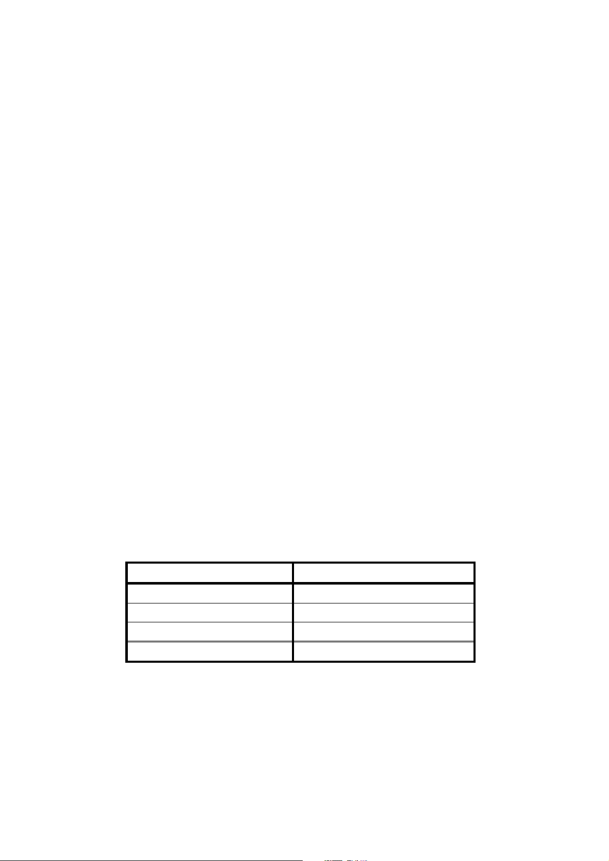
The memory capacity immediately after the initialization
Application Capacity (in byte)
Downloaded character 4,560
User-defined character 1,080
Downloaded Bitimage 10,744
Total 16,384
The capacity for the downloaded characters and the user-defined characters is readily ensured
at the initialization.
This area can be released by a command to use the area for the downloaded Bitimages.
When registering the downloaded Bitimages, calculate the remaining capacity of the memory
before registering them.
Be sure that the data with the larger capacity than the remaining capacity is ignored even if you
trying to register such data.
3-8
Page 23
CHAPTER 4
INTERFACE
This chapter describes inform ation that is requir ed when using the printer connected to a hos t, such
as the serial and parallel interface specifications.
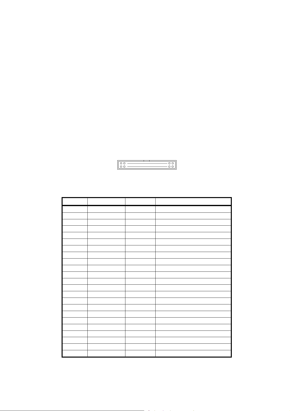
4.1 CONNECTOR TERMINAL LAYOUT
1. Interface and power connector terminal layout
Connector (plug) : XG4A-4032(Omron)
Connector signal layout
39
40
1
2
(!signal name indicates Active Low.)
Table 4-1 Connector Terminal Assignment
No. Signal name Direction Description
1 !STROBE In Parallel data input
2 to 9 DATA0 to 7 In High:1, Low:0
10 !ACK Out Acknowledge
11 BUSY Out Busy to read
12 PE Out Paper empty
13 SEL OUT Out Online High
14 !ERROR Out Error
15 !RESET In Reset (Valid in Low 20ms)
16 TxD Out Serial data ouput
17 RxD In Serial data input
18 RTS Out RS-232C Request to send
19 CTS In RS-232C Clear to send
20 NEAR_A Out Paper near end ⋅ A (+)
21 NEAR_C In Paper near end ⋅ C (+)
22 NEAR_K − Paper near end ⋅ K (−)
23 NEAR_E − Paper near end ⋅ E (−)
24 NEAR_OUT Out Paper near end signal
25 !FEED_IN In Feed signal
26 GND − Ground
27 SEL_LED+ Out SEL LED on (+)
28 SEL_LED- Out SEL LED on (−)
29 to 34 V+ − Power (+)
35 to 40 V− − Power (−)
∗ Connect to all the No.29 to 34 and No.35 to 40 terminal when supplying the power
4-1
Page 24
into V+ and V-pins. (To avoid voltage drops.)
When supplying the power through the DC socket, be sure to leave V+
and V- unconnected. Never supply the power into V+ and V- terminals,
and never short V+ and V- terminals.
∗ Use terminal numbers 22, 23 or 26 as the signal ground for RS-232C.
∗ Short terminal numbers 25 and 26 to feed the paper.
∗ SEL LED lights up at the time on-line by connecting it to terminal numbers 27 and 28.
∗ Paper near end sensor:
This printer does not have the paper near end function. However, this function can be
built in by mounting a device such as a photo sensor.
NEAR_A: Pull up it with +4.75 to +5.1 V through the current limit resistance.
NEAR_OUT: The logic of NEAR_C is inversed and output.
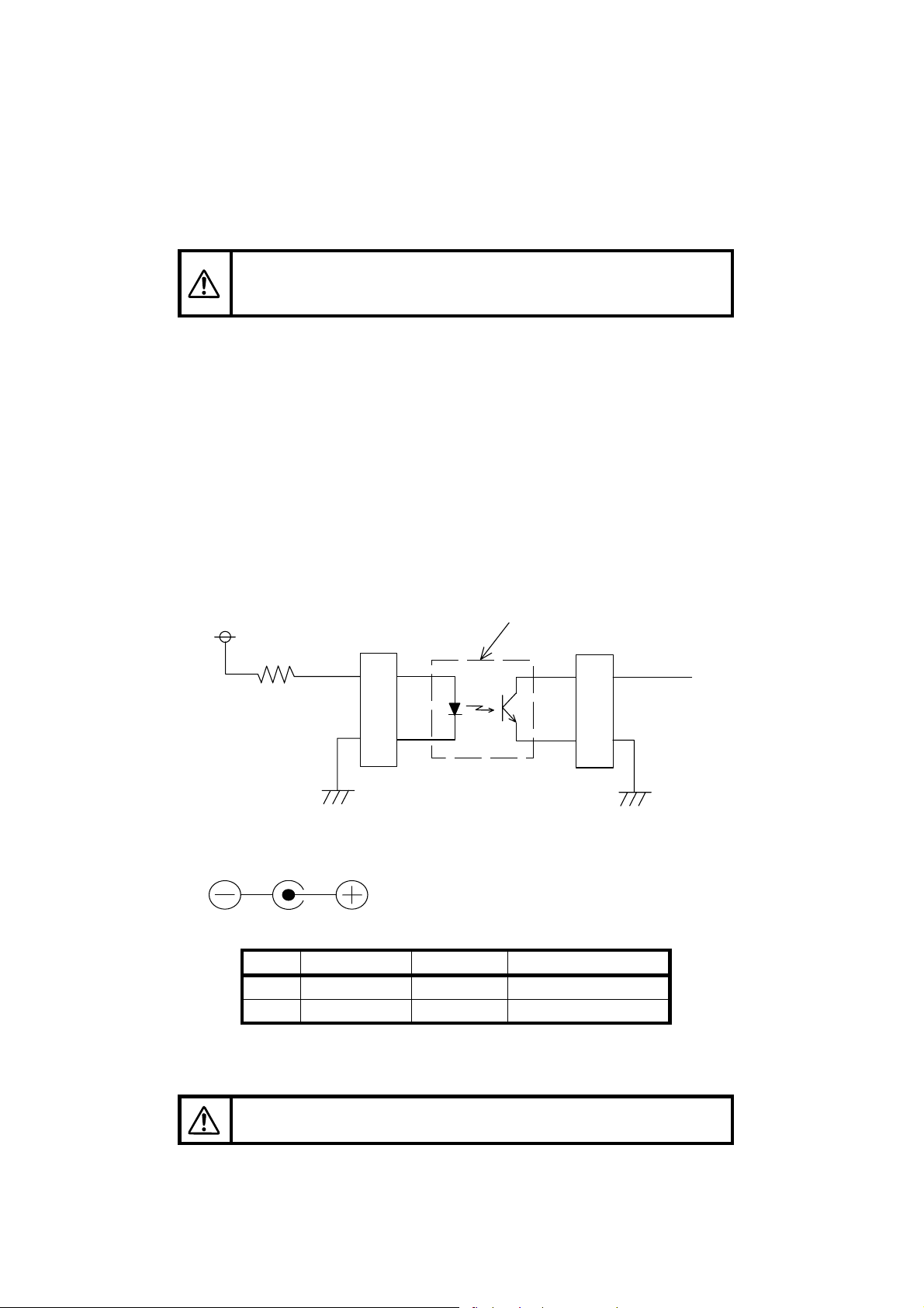
Example:
The following diagram describes how a device such as a photo sensor is mounted to
use.
フォトセンサ等
5V
220 Ω
NEARA
CN2
20
Photo sensor, etc
CN2
21
NEARC
NEARK
2. DC socket terminal layout
22
24
NEARE
Connector (Socket) : HEC0470-01-630 (Hosiden)
Polarity:
(Center plus)
Table 4-2 DC Socket Terminal Assignment
No. Signal name Direction Function
1 DC+8.7V − Power input
2 GND − Ground
∗ Supply of the power through the interface connector terminals is available, instead of the DC
socket terminal.
When supplying the power through the interface and power connector
terminals, do not connect the DC socket.
4-2
Page 25
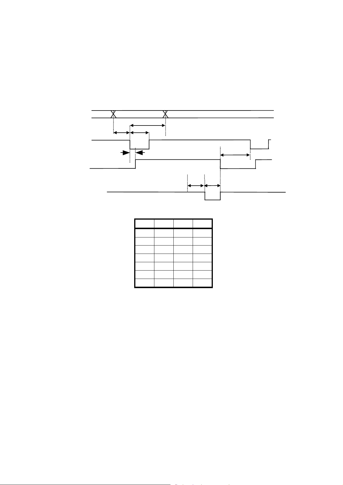
4.2 PARALLEL INTERFACE
A
1. Data input timing
DATA0 to 7
STROBE
T3
T2T1
BUSY
CK
T4
T6
T7
T5
Min. Max. Unit
T1 0.1 − µs
T2 0.5 − µs
T3 0.5 − µs
T4 − 0.5 µs
T5 0 − µs
T6 0.5 − µs
T7 − 1.0 µs
4.3 SERIAL INTERFACE
1. Hardware control
The RTS signal (Low or High) controls the transmission of the data from a host computer.
When the data st ored in the input buf f er of the pr inter ex c eeds 4,046 bytes, the RTS s ignal turns
Low.
Once the RTS signal turns Low, the host computer stops to transmit the data.
If the data stored in the input buffer of the printer falls below 3,995 bytes, the RTS signal turns
High.
Once the RTS signal turns High, the host computer resumes transmitting the rest of the data.
∗ When the printer fails (for example, paper-out), the RTS signal also turns Low.
And then, after the printer gets back to normal, the RTS signal turns High.
4-3
Page 26
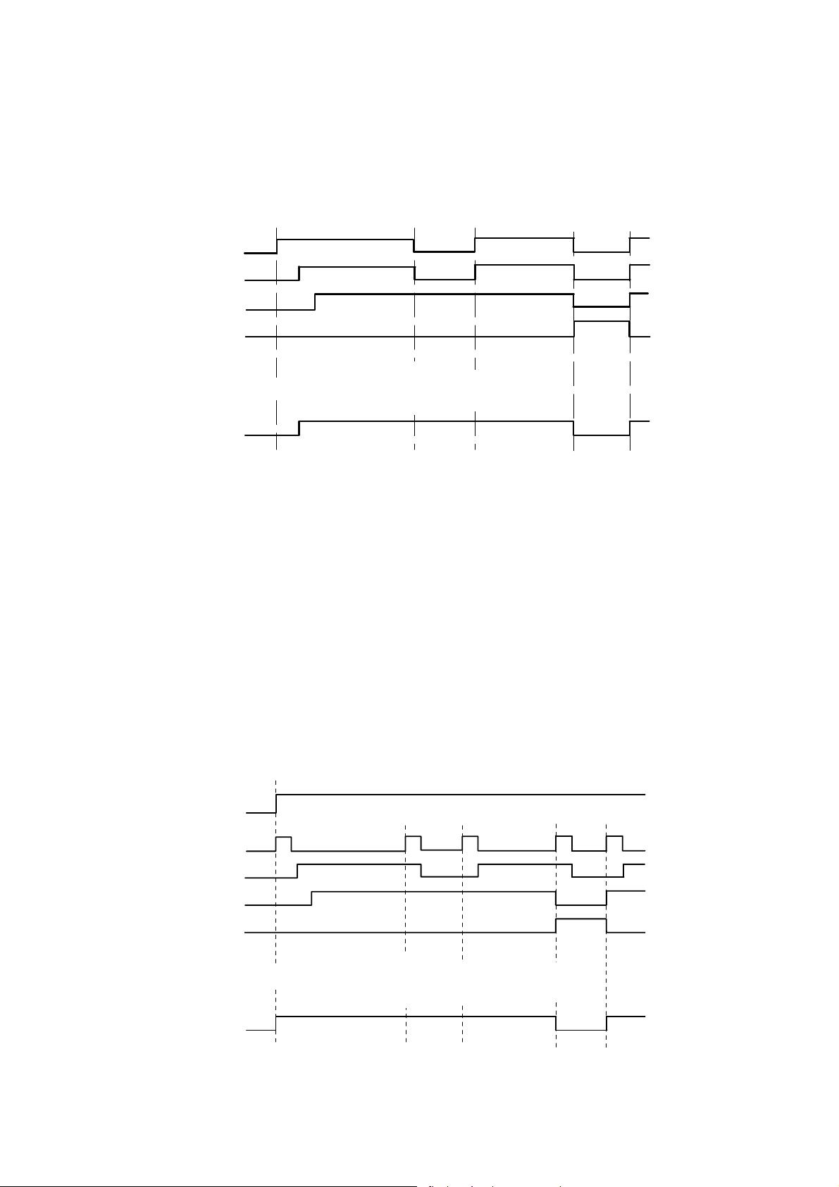
Data timing for hardware control
RTS
RTS
RxD
RxD
Print
プリント
Paper out
紙無し
ON-LINE
ON‑LINE
OFF‑LINE
OFF-LINE
Power ON
電源ON
4046バイト以 上 3995バイト 以 下
Buffer
バッファ
4,046 bytes
or more
Buffer
バッファ
3,995 bytes or less
2. Xon/Xoff control
The data transmission from a host computer is controlled through the exchange of Xon(11
command and Xoff(13
When the data stored in the input buff er of the pr inter ex ceeds 4,046 bytes, the printer sends the
Xoff command to the host computer.
Upon the reception of the Xoff command, the host computer stops to send the data.
If the data stored in the input buffer of the printer falls below 3,995 bytes, the printer sends the
Xon command to the host computer.
Upon the reception of the Xon com mand, the host computer resum es sending the rest of the
data.
∗ When the printer fails (for exam ple, paper-out), the printer sends the Xoff c ommand to the
host computer.
And then, after the printer gets back to normal, the printer sends the X on command to the
host computer.
Data timing for Xon/Xoff control
) command between the printer and the host computer.
16
)
16
RTS
RTS
RxD
TxD
RxD
RxD
Print
プリント
紙無し
Paper out
ON‑LINE
ON-LINE
OFF‑LINE
OFF-LINE
Xon
Xon
電源ON
Power ON
4046バイト 以 上 3995バイト以 下
Xoff
Xoff
Buffer
バッファ バッファ
4,046 bytes
or more
4-4
Xon
Buffer
3,995 bytes or less
Xoff
Xoff Xon Xon
Xon
Page 27

3. Input / Output signal specifications
Table 4-3 I/O Signal Specifications
Item Condition
High input voltage !RESET 1.76 − 5.5 V
Low input voltage !RESET 0 − 1.44 V
High input voltage
Low input voltage
High input voltage RXD, CTS +2.8 − +15 V
Low input voltage RXD, CTS −15 − −2.8 V
High output voltage
Low output voltage
High output voltage
Low output voltage
DATA0 to 7, !STROBE,
!FEED_IN, NEAR_C
DATA0 to 7, !STROBE,
!FEED_IN, NEAR_C
BUSY, !ACK, !ERROR,
SEL OUT, PE, NEAR_OUT
BUSY, !ACK, !ERROR,
SEL OUT, PE, NEAR_OUT
TXD, RTS
( RL = 3 KΩ)
TXD, RTS
( RL = 3 KΩ)
Rate Value
Min Typ. Max
3.15
0
4.75 − 5.1 V
0 − 0.5 V
+5
−15
−
−
+9 +15 V
−9 −5 V
5.5 V
1.35 V
Unit
4-5
Page 28

4-6
Page 29

CHAPTER 5
COMMAND FUNCTION
This chapter describes the functions of the commands processed by the printer.
5.1 FUNCTION OUTLINE
DPU-30 has two sets of commands: Mode 1/Mode 2 and Mode 3. The commands are as listed
below:
5.1.1 Mode 1/Mode 2
1. Basic commands (DPU-20-20CF/24CF compatible commands)
Command Function See page
CR Line Feed 5-7
LF Carriage Return 5-7
SO Double–Width Printing Mode Specify 5-7
SI Double–Width Printing Mode Clear 5-8
CAN Cancel 5-8
ESC S Bitimage Graphic 5-8
ESC c Special Character Specify 5-9
ESC R International Character Specify 5-9
2. Extension commands
Command Function See page
ESC @ Initialization 5-10
DC2 > Print Drive Mode Select 5-10
DC2 % Print Drive User Define 5-11
DC2 ~ Print Density Set 5-11
5-1
Page 30

5.1.2 Mode 3
1. Paper feed commands
Command Function See page
CR Carriage Return 5-12
LF Line Feed 5-12
FF Page Length Print 5-12
ESC J Print and Feed Forward 5-13
ESC j Print and Feed Backward 5-13
ESC d Print and Continuous Line Feed 5-13
ESC C Page Length Set 5-14
2. Tab commands
Command Function See page
HT Horizontal Tab 5-15
ESC D Horizontal Tab Set 5-15
3. Form commands
Command Function See page
ESC 2 Default Amount of Line Spacing Specify 5-16
ESC 3 Amount of Line Spacing Set 5-16
ESC SP Standard Size Character Right Spacing
Set
5-16
GS L Left Margin Set 5-17
GS W Width of Printing Area Set 5-17
ESC $ Absolute Position of Printing Area Specify 5-18
ESC a Position Align 5-18
4. Character decoration commands
Command Function See page
ESC ! Decorated Characters Collectively Specify 5-19
ESC G
ESC E
Bold Characters Specify and Clear
5-20
ESC { Inversion (Flip) Specify and Clear 5-20
ESC - Underline Specify and Clear 5-21
GS ! Character Size Set 5-21
GS B Reverse Character Specify and Clear 5-22
5-2
Page 31

5. Character selection commands
Command Function See page
ESC M Font Select 5-23
ESC R International Character Select 5-24
ESC & Downloaded Character Register 5-25
ESC ? Downloaded Character Delete 5-25
ESC % Downloaded Character Specify and Clear 5-26
6. Barcode commands
Command Function See page
GS H HRI Character Printing Set 5-27
GS w Width of Barcode Set 5-27
GS h Height of Barcode Set 5-28
GS k Barcode Print 5-29
7. Ruled line control commands
Command Function See page
DC3 A Ruled Line Buffer A Select 5-30
DC3 B Ruled Line Buffer B Select 5-30
DC3 C Ruled Line Buffer Clear 5-30
DC3 D Write in Position Specified by Dot in Ruled
Line Buffer
DC3 L Write in Position Specified by Line in
Ruled Line Buffer
DC3 + Print Mode of Ruled Line Approve 5-32
DC3 − Print Mode of Ruled Line Prohibit 5-32
DC3 P 1 Dot Line of Ruled Line Print 5-32
8. Response commands (only for serial mode)
Command Function See page
GS a Validity / Invalidity of Automatic Status
Transmission and Real Time Command
Select
GS r Status Transmit 5-34
DLE EOT Status Transmit in Real Time 5-35
DLE ENQ Major Buffers Clear in Real Time 5-36
5-31
5-31
5-33
5-3
Page 32

9. Bitimage commands
Command Function See page
ESC ∗ Bitimage Select 5-37
GS ∗ Downloaded Bitimage Register 5-38
GS / Downloaded Bitimage Print 5-39
10. Kanji commands
Command Function See page
FS & Kanji Mode Specify 5-40
FS . Kanji Mode Clear 5-40
FS C Kanji Code System Select 5-40
FS S Character Spacing for Kanji Set 5-41
FS ! Print Mode for Kanji Collectively Specify 5-42
FS − Underline of Kanji Specify and Clear 5-43
FS W Double-Width and Double-Height Kanji
Set and Clear
5-43
FS 2 User-Defined Character Register 5-44
11. Function and setting commands
Command Function See page
ESC @ Initialization 5-46
CAN Print Buffer Clear 5-46
DC2 D Registration Area of Downloaded
Character Ensure and Release
DC2 G Registration Area of User-Defined
Character Ensure and Release
5-47
5-47
DC2 > Print Drive Mode Select 5-48
DC2 % Print Drive User-Define 5-49
DC2 ~ Print Density Set 5-49
5-4
Page 33

5.2 FUNCTION CODES
All commands start with one of the following control codes (called function codes hereinafter):
LF (0A
FS (1C
), CR (0D16), SO (0E16), SI (0F16), DC2 (1216), DC3 (1316), CAN (1816), ESC (1B16),
16
), DEL (7F16)
16
Some function codes form a command by itself and others are followed by parameters and/or image
data.
The number of bytes configuring a command differs from command to command. The shortest
commands consist of 1-byte and the longest, some hundred bytes.
5.3 CHARACTER CODES
This section describes the character codes in detail.
The character codes are classified into two groups: 1-byte character codes and 2-byte character
codes. The 1-byte character codes are used to print standard-size characters, whereas the 2-byte
character codes print Kanji, user-defined characters.
In Mode 1 and Mode 2, the printer uses only the 1-byte character codes.
The following subsections describe the 1-byte and 2-byte character codes individually.
5.3.1 1-Byte Character Codes
Used for standard size character printing.
The hexadecimal codes valid as the 1-byte character codes are as shown below:
• 20
to FF16 (Some character tables make codes 7F16 and FF16 invalid.)
16
5.3.2 2-Byte Character Codes
The 2-byte character codes are invalid in mode 1 and 2. The 2-byte character codes are used to
print Kanji, and user-defined characters when in the Kanji mode.
• The first byte
through 2016: Function codes are processed as function codes (See 5.2 FUNCTION
00
16
CONDES). All the other codes are ignored.
If the second-byte code is received along with a Kanji mode clear
command, the next received data is processed as a 1-byte character
code.
through 7E16: First byte of a JIS Kanji code.
21
16
through FF16: Ignored.
7F
16
5-5
Page 34

• The second byte
through 1F16: The first byte already entered is ignored. Function codes are processed
00
16
as function codes. All the other codes are ignored along with the first
byte. If the following code accompanies a Kanji mode clear command,
the next received data is processed as a 1-byte character code.
: Ignored along with the first byte.
20
16
through 7E16: Print Kanji or user-defined characters if the first byte is one of 2116
21
16
through 7E
: Ignored along with the first byte.
7F
16
through FE16: Ignored along with the first byte unless the first byte is 0016.
80
16
: Ignored along with the first byte.
FF
16
.
16
For the correspondence between the 2-byte codes and the printed characters, refer to “Kanji Code
Table” (as per JIS C 6226-1983).
5.4 FUNCTION CODE DESCRIPTION
This chapter describes the commands in each function by the mode.
5.4.1 Function Code Description Format
Each function code is described in the format below.
The same format is used for both Mode 1/Mode 2 and Mode 3.
X X
Indicates
X X X X
the command. Indicates the command name.
Code Indicates command part and parameter past.
X
indicates hexadecimal code.
16
Function Indicates the functions of the commands.
Details Explains detailed printer operation when inputting commands.
5-6
Page 35

5.4.2 Mode 1/Mode 2
1. Basic command
CR Carriage Return
Code
Function
Details
0D
16
Prints the data stored in the print buffer, and then starts a new line according to the
defined amount of paper feed for one line.
• After executing this command, a head of a line is set as a starting position of
printing.
• LF command received immediately following CR is ignored.
• The amount of paper feed for one line is fixed at 24-dot pitch.
LF Line Feed
Code
Function
Details
0A
16
Prints the data stored in the print buffer, and then starts a new line according to the
defined amount of paper feed for one line.
• After executing this command, a head of a line is set as a starting position of
printing.
• LF command received immediately following CR is ignored.
• The amount of paper feed for one line is fixed at 24-dot pitch.
SO Double–Width Printing Mode Specify
Code
Function
Details
0E
16
Specifies the double−width printing. Hereafter, the width of characters to be printed
is doubled.
• This command is not cancelled until either ESC @ or SI command is entered.
5-7
Page 36

SI Double–Width Printing Mode Clear
Code
Function
0F
16
Clears the double−width printing.
CAN Cancel
Code
Function
18
16
Clears the print buffer.
Details
• After executing this command, a head of a line is set as a starting position of
printing.
ESC S n1 n2 n3 n4 Bitimage Graphic
Code
Domain of
function
Function
+ 5316 + n1 + n2 + n3 + n4 + [DATA]
1B
16
≤ n1, n2, n3, n4 ≤ 3916
30
16
“0001” ≤ “n1 n2 n3 n4” ≤ “1023”
0 ≤ d ≤ 255 (graphic data)
The number of data specified in ASCII code n1, n2, n3 and n4 are specified as a
Bitimage.
Example: Case that 192 Bitimages are specified
1B
+ 5316 + “0192” + . . . . . . . . .
16
[192 DATA]
Details
• The code outside the domain of function processes the data as the 1-byte data
thereafter.
• If the dots are specified outside the printing area, the data is ignored.
• The data deployment position is set in accordance with the predefined starting
position of the data deployment.
• This command is affected by the inverse printing.
• If the next Bitimage Specify command is received at the occurrence of the line
overflow, the data of the previous line stored in the print buffer is printed. The line
overflow is determined according to the number of dots described below.
− Mode 1: Determined as the line overflow if the number of dots exceeds 276.
− Mode 2: Determined as the line overflow if the number of dots exceeds 332.
• Refer to the figure shown below for how the data is deployed.
5-8
Page 37

(Input i mage) (Deploy ment imag e)
d1 d2 d3
MSB
d1 d2 d3
LSB
ESC c Special Character Specify
Code
Function
+ 6316
1B
16
Replaces the character code table from F9
to FD16 as follows.
16
Category F916 FA16 FB16 FC16 FD16
1 (default value) 市 区 町 村 人
2 Σ μ Ω π δ
Details
• The operation is executed as a toggle operation.
• The table is changed when this command is executed.
ESC R n International Character Specify
Code
Domain of
1B
+ 5216 + n
16
0 ≤ n ≤ 6
function
Function
Selects a set of characters of each country described below.
The characters are replaced with only the characters of a country of specified
corresponding code according to the katakana – compliant character code table
(refer to “APPENDIX B. DATA CODE TABLE.”).
Details
• The data beyond the defined domain of function is ignored.
• In default, n = 0.
5-9
Page 38

2. Extension commands
ESC @ Initialization
Code
Function
+ 4016
1B
16
Initializes the printer.
Details
• The allocation of the user memory is initialized.
• The receive buffer is retained.
• The print buffer is cleared.
• The settings of each command are initialized.
• ROM SW is reread.
DC2 > n Print Drive Mode Select
Code
Domain of
+ 3E16 + n
12
16
0 ≤ n ≤ 2
function
Function
Sets the print drive mode.
n Print drive mode Feature
0 High speed mode The printer is driven at high speed and high
electric power.
1 Medium speed mode 1 The printer is driven at medium speed and low
electric power.
2 Medium speed mode 2 The printer is driven at our recommended electric
power. The speed of printing in this mode is slower
than that in the medium speed mode 1.
Details
• Even if our recommended electric power is adopted in the high speed mode, the
print speed may slow depending on the print ratio.
• In default, n = 2.
5-10
Page 39

DC2 % n Print Drive User Define
Code
Domain of
+ 2516 + n
12
16
1 ≤ n ≤ 16
function
Function
Executes the printing according to the print drive defined by a user.
n = 1: The amount of 1 × 8 dots
n = 16: The amount of 16 × 8 dots
Details
• When one line is printed, the number of division is calculated every n × 8 dots.
Example: Suppose that the number of dots printed = 128 dots, and n = 1
128 ÷ (1 × 8) = 16 (one line printed is divided into 16 parts)
• The smaller the value of n, the lower the required electric power. And the bigger
the value of n, the faster the speed of printing.
DC2 ~ n Print Density Set
Code
Domain of
+ 7E16 + n
12
16
0 ≤ n ≤ 255
function
Function
Sets the print density.
Details
• n means n%.
• When adjusting the print density double for low heat sensitive paper, set n=200.
• The print density cannot be set for each character. The print density can be set
for each line.
• In default, n = 100.
5-11
Page 40

5.4.3 Mode 3
A
1. Paper feed commands
CR Carriage Return
Code
Function
Details
0D
16
Prints the data stored in the print buffer, and then starts a new line according to the
defined amount of paper feed for one line.
• After executing this command, a head of a line is set as a starting position of
printing.
• LF command received immediately following CR is ignored.
LF Line Feed
Code
Function
0A
16
Provides the same function as CR.
Details
fter executing this command, a head of a line is set as a next starting position of
•
printing.
• LF command received immediately following CR is ignored.
FF Page Length Print
Code
Function
0C
16
Feeds paper based on the setting of page length.
Details
• After executing this command, a head of a line is set as a next starting position of
printing.
5-12
Page 41

ESC J n Print and Feed Forward
A
A
Code
Domain of
+ 4A16 + n
1B
16
0 ≤ n ≤ 255
function
Function
Prints the data stored in the print buffer, and then feeds paper n × dot pitch forward.
Details
• After executing this command, a head of a line is set as a next starting position of
printing.
• This function is not affected by the setting of the amount of line spacing.
ESC j n Print and Feed Backward
Code
Domain of
+ 6A16 + n
1B
16
0 ≤ n ≤ 255
function
Function
Details
Prints the data stored in the print buffer, and then feeds paper n × dot pitch
backward.
fter executing this command, a head of a line is set as a next starting position of
•
printing.
• This function is not affected by the setting of the amount of line spacing.
ESC d n Print and Continuous Line Feed
Code
Domain of
+ 6416 + n
1B
16
0 ≤ n ≤ 255
function
Function
Prints the data stored in the print buffer, and then feeds paper n lines forward.
Details
fter executing this command, a head of a line is set as a next starting position of
•
printing.
5-13
Page 42

ESC C n Page Length Set
Code
Domain of
+ 4316 + n
1B
16
1 ≤ n ≤ 255
function
Function
Sets the amount of page feed.
Details
• The page feed is executed using the FF command.
5-14
Page 43

2. Tab commands
HT Horizontal Tab
Code
Function
09
16
Moves the printing position to the position of the next horizontal tab.
Details
• If the position of the horizontal tab is not set, this command is ignored.
• If the position of the horizontal tab is out of the printing area, it is set at the head
of the next line.
• The position of the horizontal tab is set using the ESC D command.
• The default value of the horizontal tab is 8 character pitches.
ESC D n1...nk NUL Horizontal Tab Set
Code
Domain of
function
Function
+ 4416 + n1...nk + 0016
1B
16
1 ≤ n ≤ 255
0 ≤ k ≤ 32
Sets the position of the horizontal tab.
n describes the number of characters from the head of a line to the position at
which the horizontal tab is set.
k describes the number of data to be set.
Details
• The position of the horizontal tab to be set is [character width × n].
→ The character width includes the right space and the horizontal scaling factor.
• All the values previously set are cleared.
• The maximum number of horizontal tab positions settable is 32. If the number
exceeds the limit, the rest of the data is processed as normal data.
• The positions are set in ascending order. And the final value is NUL code.
• If the smaller value is set than previously set value, such value is recognized as
NUL code.
• Even if changing the width of character after setting, the position of tab set is not
changed.
5-15
Page 44

3. Form commands
ESC 2 Default Amount of Line Spacing Specify
Code
Function
+ 3216
1B
16
Restores the amount of paper feed for one line to its default value.
ESC 3 n Amount of Line Spacing Set
Code
Domain of
+ 3316 + n
1B
16
0 ≤ n ≤ 255
function
Function
Sets the amount of paper feed for one line at [n × dot pitch].
Details
• The default amount of paper feed for one line, n = 28.
ESC SP n Standard Size Character Right Spacing Set
Code
Domain of
+ 2016 + n
1B
16
0 ≤ n ≤ 127
function
Function
Sets the character spacing for standard size character at [n × dot pitch].
Details
• The right character spacing increases depending on the horizontal scaling factor.
• This command does not affect kanji.
• In default, n = 0.
5-16
Page 45

GS L nl nh Left Margin Set
Code
Domain of
function
Function
+ 4C16 + nl + nh
1D
16
0 ≤ nl ≤ 255
0 ≤ nh ≤ 255
Sets the left margin at [(nh × 256 + nl) × dot pitch].
Details
• This setting is only valid at a head of a line.
• The maximum settable left margin corresponds to the horizontally printable area.
• When a setting value exceeds maximum value, the setting value is replaced
within printable maximum area.
• In default, nh and nl = 0.
GS W nl nh Width of Printing Area Set
Code
Domain of
function
Function
+ 5716 + nl + nh
1D
16
0 ≤ nl ≤ 255
0 ≤ nh ≤ 255
Sets the width of the printing area at [(nh × 256 + nl) × dot pitch]
Details
• This setting is only valid at a head of a line.
• The settable printing area corresponds to the horizontally printable area except
for the left margin. If printable range is exceeded, it replaces to the horizontally
printable maximum area except the left margin.
• In default, nh × 256 + nl = 384.
5-17
Page 46

ESC $ nl nh Absolute Position of Printing Area Specify
Code
Domain of
function
Function
Details
+ 2416 + nl + nh
1B
16
0≤ nl ≤ 255
0 ≤ nh ≤ 255
0 ≤ nh × 256 + nl ≤ 127
Sets the printing area at the absolute position based on the left margin. The setting
range is [(nh × 256 + nl) × dot pitch].
• This setting is only valid at a head of a line.
• The value of setting exceeding the maximum value of nh or nl invalidates this
command.
ESC a n Position Align
Code
Domain of
+ 6116 + n
1B
16
0 ≤ n ≤ 2
function
Function
Aligns one line of data to be printed in the specified position.
n = 0: left – aligned
n = 1: center – aligned
n = 2: right – aligned
Details
• This function makes an alignment within the predefined printing area.
• In default, n = 0.
5-18
Page 47

4. Character decoration commands
ESC ! n Decorated Characters Collectively Specify
Code
Domain of
+ 2116 + n
1B
16
0 ≤ n ≤ 255
function
Function Collectively specifies the printing modes.
Bit Description
Function
0 1
0 Font 24 dot type 16 dot type
1 Undefined − −
2 Undefined − −
3 Bold character clear specify
4 Double–height character clear specify
5 Double–width character clear specify
6 Undefined − −
7 Underline clear specify
Details
• When specifing both Bit 4 and Bit 5 described in the table above, the
double-height and double-width size characters are printed.
• The dot pitch of underline is 2 dot pitch. However, if the several underlines with
the different thicknesses exist in one line, the thickness of those underlines will be
brought into line with the thickest underline.
• Each setting is not related to the previous settings.
• The settings of the characters except for the bold characters and the font are
valid only for the standard size characters.
• In default, n = 0.
5-19
Page 48

ESC G n
ESC E n Bold Characters Specify and Clear
Code
Domain of
+ 4716 + n
1B
16
1B
+ 4516 + n
16
0 ≤ n ≤ 255
function
Function
Specifies and clears the bold characters.
n = <xxxxxxx0>B: The bold characters are cleared.
n = <xxxxxxx1>B: The bold characters are specified.
Details
• n is valid only for the least significant bit.
• In default, n = 0.
ESC { n Inversion (Flip) Specify and Clear
Code
Domain of
+ 7B16 + n
1B
16
0 ≤ n ≤ 255
function
Function
Specifies and clears the inversion.
n = <xxxxxxx0>B: The inversion is cleared.
n = <xxxxxxx1>B: The inversion is specified.
Details
• n is valid only for the least significant bit.
• This setting is valid only at a head of a line.
• In default, n = 0.
5-20
Page 49

ESC – n Underline Specify and Clear
Code
Domain of
+ 2D16 + n
1B
16
0 ≤ n ≤ 255
function
Function
Specifies and clears the underline.
n = <xxxxx000>B: underline 0 dot pitch
n = <xxxxx111>B: underline 7 dot pitch
Details
• n is valid only for the low 3 bits.
• This setting is valid only for the standard size characters.
• The underline is added to the width of character and the character spacing.
• This function is not affected by the setting of the amount of line specing.
• If the several underlines with the different thicknesses exist in one line, the
thickness of those underlines will be brought into line with the thickest underline.
• In default, n = 0.
GS ! n Character Size Set
Code
Domain of
+ 2116 + n
1D
16
0 ≤ n ≤ 255
function
Function
Specifies the character size.
n = <xxxx0000>B: scaling factor in the vertical direction : × 1 <minimum>
n = <xxxx0111>B: scaling factor in the vertical direction : × 8 <maximum>
n = <0000xxxx>B: scaling factor in the horizontal direction : × 1 <minimum>
n = <0111xxxx>B: scaling factor in the horizontal direction : × 8 <maximum>
Details
• This setting is valid for any type of characters other than HRI characters.
• n is valid only for 0 to 2 bits and 4 to 6 bits.
• In default, n = 0.
5-21
Page 50

GS B n Reverse Character Specify and Clear
Code
Domain of
+ 4216 + n
1D
16
0 ≤ n ≤ 255
function
Function
Specifies and clears the reverse characters.
n = <xxxxxxx0>B: The reverse characters are cleared.
n = <xxxxxxx1>B: The reverse characters are specified.
Details
• n is valid only for the least significant bit.
• In default, n = 0.
5-22
Page 51

5. Character selection commands
ESC M n Font Select
Code
Domain of
+ 4D16 + n
1B
16
0 ≤ n ≤ 255
function
Function
Selects the character font.
n = <xxxxxxx0>B: character font (12 × 24 and 24 × 24)
n = <xxxxxxx1>B: character font (8 × 16 and 16 × 16)
Details
• n is valid only for the least significant bit.
• This setting is also valid for Kanji.
• The character font can be set by ESC ! command but the setting by the command
which has been processed at last becomes valid.
• In default, n = 0.
5-23
Page 52

ESC R n International Character Select
Code
Domain of
+ 5216 + n
1B
16
0 ≤ n ≤ 7
function
Function
Details
Selects a set of characters of each country described below.
When selecting JAPAN, the set of characters corresponds to the katakana –
compliant character code table (refer to APPENDIX B. DATA CODE TABLE.).
When selecting a set of characters other than JAPAN, the characters are replaced
with only the characters of a country of specified corresponding code according to
PC 437 code table (refer to APPENDIX B. DATA CODE TABLE.).
• The data beyond the defined domain of function is ignored.
• In default, n = 0.
5-24
Page 53

ESC & y c1 c2 [x1 d1...d(y×x1)]...[xk d1...d(y×xk)] Downloaded Character Register
Code
Domain of
function
+ 2616 + y + c1 + c2 [x1 d1...d (y × x1)]...[xk d1...d (y × xk)]
1B
16
y = 3
20
≤ c1 ≤ c2 ≤ 7E16
16
0 ≤ x ≤ 12 (When font (12 × 24) is selected)
0 ≤ x ≤ 9 (When font (8 × 16) is selected)
0 ≤ d1…d (y × xk) ≤ 255
Function
Defines the downloaded pattern for the specified character code.
y : The number of bytes in the vertical direction
x : The number of bits in the horizontal direction
c1 : Start code of character definition
c2 : End code of character definition
Details
• When defining only one character, c1 is equal to c2.
• d means the graphic data of the downloaded characters,
• The residual right space generated by specifying x is processed as blank.
• The code previously registered is overwritten.
• When making the registered font valid, set ESC %.
• The maximum output for 16 bit type fonts is 8 dots (width) × 16 dots (height).
ESC ? n Downloaded Character Delete
Code
Domain of
1B
16
20
16
+ 3F16 + n
≤ n ≤ 7E16
function
Function
Deletes the downloaded characters of the specified code.
Details
• n means the defined character code. After deleting the downloaded characters,
the internal characters are printed.
• If the specified character code is undefined, this command is ignored.
5-25
Page 54

ESC % n Downloaded Character Specify and Clear
Code
Domain of
+ 2516 + n
1B
16
0 ≤ n ≤ 255
function
Function
Specifies and clears the downloaded character set.
n = <xxxxxxx0>B: The downloaded character set is cleared.
n = <xxxxxxx1>B: The downloaded character set is specified.
Details
• n is valid only for the least significant bit.
• When clearing the downloaded character set, specify the internal character set.
• When specifying the downloaded character set, specify the downloaded
characters for the defined code and the internal characters for the undefined
code.
• In default, n = 0.
5-26
Page 55

⋅⋅⋅
⋅⋅⋅
⋅⋅⋅
⋅⋅⋅
⋅⋅⋅
⋅⋅⋅
Image of registration
Font 12 × 24
d1
d2
d5
d3 d36
d6
Font 12 × 24
d1
d2
d5
⋅ ⋅ ⋅
⋅ ⋅ ⋅
⋅ ⋅ ⋅
⋅ ⋅ ⋅
⋅ ⋅ ⋅
d34d4
d35
Character output range
d34d4
d35
Font 8 × 16
d1
d2
d5
d3 d27
d6
Font 8 × 16
d1
d2
d5
d25 d4
d26
d22 d4
d23
MSB
LSB
d3 d36
d6
⋅ ⋅ ⋅
5-27
Page 56

6. Barcode commands
GS H n HRI Character Printing Set
Code
Domain of
+ 4816 + n
1D
16
0 ≤ n ≤ 255
function
Function
Specifies the printing position of the HRI characters when printing a Barcode.
n = <xxxxxx00>B: HRI characters are not printed.
n = <xxxxxx01>B: HRI characters are printed on top of the Barcode.
n = <xxxxxx10>B: HRI characters are printed below the Barcode.
n = <xxxxxx11>B: HRI characters are printed on top of and below the Barcode.
Details
• n is valid only for the low 2 bits.
• In default, n = 0.
GS w n Width of Barcode Set
Code
Domain of
+ 7716 + n
1D
16
1 ≤ n ≤ 4
function
Function Sets the width of Barcode.
Module width of
n
JAN/UPCE
Module width of ITF, CODE39, and CODABAR
Narrow bar Wide bar
1 2 dot pitch 1 dot pitch 3 dot pitch
2 3 dot pitch 2 dot pitch 5 dot pitch
3 4 dot pitch 3 dot pitch 8 dot pitch
4 5 dot pitch 4 dot pitch 10 dot pitch
Details
• For CODE128, the width of a Barcode cannot be set (the module width is fixed at
2 dot pitch).
• In default, n = 2.
5-28
Page 57

GS h n Height of Barcode Set
Code
Domain of
+ 6816 + n
1D
16
1 ≤ n ≤ 255
function
Function
Sets the height of Barcode.
Details
• In default, n = 162.
5-29
Page 58

GS k m d1...dk NUL Barcode Print
Code
Domain of
function
Function
+ 6B16 + m + d1...dk + NUL
1D
16
1 ≤ m ≤ 7
The values of d1 to dk depend on a type of Barcode.
Selects a type of Barcode and prints the Barcode.
m Type of Barcode
1 UPC-E
2 JAN13
3 JAN8
4 CODE39
5 ITF
6 CODABAR
7 CODE128
Details
• This command is finished by a NUL code.
• UPC−E is the 7-byte Barcode data and internally adds a check digit.
• JAN13 is the 12-byte Barcode data and internally adds a check digit.
• JAN8 is the 7-byte Barcode data and internally adds a check digit.
• CODE39 automatically adds the start and stop modules.
• ITF is the even number-byte Barcode data and automatically adds the start and
stop modules.
• CODE128 transmits the start module and the Barcode data. And the check digit
and the stop module are automatically added.
If the special characters are included in the data, specify them at 2 bytes as
follows.
SHIFT → 7B
CODE A → 7B
CODE B → 7B
CODE C → 7B
FNC 1 → 7B
FNC 2 → 7B
FNC 3 → 7B
FNC 4 → 7B
’{’ → 7B
, 5316 ({S)
16
, 4116 ({A)
16
, 4216 ({B)
16
, 4316 ({C)
16
, 3116 ({1)
16
, 3216 ({2)
16
, 3316 ({3)
16
, 3416 ({4)
16
, 7B16 ({{)
16
Example) When printing Start Code C, Fnc 1, and 0012, (where n = 7),
send 1D
, 6B16, 0716, 6916, 7B16, 3116, 3016, 3016, 3116, 3216, 0016
16
in this order.
5-30
Page 59

7. Ruled line control commands
DC3 A Ruled Line Buffer A Select
Code
Function
+ 4116
13
16
Selects the ruled line buffer A.
Details
• This function selects the ruled line buffer A.
• There are 2 independent buffers (A and B) as the ruled line buffer.
• The ruled line buffer A is selected as the default.
DC3 B Ruled Line Buffer B Select
Code
Function
+ 4216
13
16
Selects the ruled line buffer B.
Details
• This function selects the ruled line buffer B.
• The ruled line buffer A is selected as the default.
DC3 C Ruled Line Buffer Clear
Code
Function
+ 4316
13
16
Clears the contents of the selected ruled line buffer.
Details
• The whole data is cleared to 0.
5-31
Page 60

DC3 D nl nh Write in Position Specified by Dot in Ruled Line Buffer
Code
Domain of
function
Function
Details
+ 4416 + nl + nh
13
16
0 ≤ nl ≤ 255
0 ≤ nh ≤ 3
Writes 1 in the specified position in the ruled line buffer.
The position is set at [(nh × 256 + nl) × dot pitch].
• Regardless of the printable area, this function writes 1 in the selected ruled line
buffer.
• nh is valid only for the low 2 bits.
DC3 L nl nh ml mh Write in Position Specified by Line in Ruled Line Buffer
Code
Domain of
function
+ 4C16 + nl + nh + ml + mh
13
16
0 ≤ nl ≤ 255
0 ≤ nh ≤ 3
0 ≤ ml ≤ 255
0 ≤ mh ≤ 3
Function
Writes 1 in the range from nhnl to mhml in the ruled line buffer.
0 ≤ nhnl ≤ mhml ≤ 1023
nhnl = (nh × 256 + nl) × dot pitch
mhml = (mh × 256 + ml) × dot pitch
Details
• Regardless of the printable area, this function writes 1 in the selected ruled line
buffer.
• nh and mh are valid only for the low 2 bits.
5-32
Page 61

DC3 + Print Mode of Ruled Line Approve
Code
Function
+ 2B16
13
16
Approves the print mode of the data stored in the ruled line buffer.
Details
• When a printing command (CR, LF, etc.) is executed after the approval, the data
stored in the selected ruled line buffer is always included in the data to be printed.
• This command is not affected by the printing area commands such as GS L, and
GS W.
• In default, the print mode of the data stored in the ruled line buffer is prohibited.
DC3 – Print Mode of Ruled Line Prohibit
Code
Function
+ 2D16
13
16
Prohibits the print mode of the data stored in the ruled line buffer.
Details
• After the print mode of the ruled line is cancelled, the data stored in the ruled line
buffer is not printed.
DC3 P 1 Dot Line of Ruled Line Print
Code
Function
Details
+ 5016
13
16
Prints the data stored in the print buffer and 1 dot line of the data in the selected
ruled line buffer.
• Even if no data exists in the print buffer, 1 dot line of the data in the selected ruled
line buffer is printed.
• If the print mode of the data stored in the ruled line buffer is prohibited, none of
the data is printed.
5-33
Page 62

8. Response commands (only for serial mode)
GS a n Validity / Invalidity of Automatic Status Transmission and Real Time Command Select
Code
Domain of
+ 6116 + n
1D
16
0 ≤ n ≤ 3
function
Function
Specifies the validity or invalidity of the automatic status response which is one of
the printer statuses.
Specifies the validity or invalidity of the real time command.
n = 0: The automatic status response becomes invalid.
n = 1: The automatic status response becomes valid. And the current status is
returned.
n = 2: The real time command becomes invalid.
n = 3: The real time command becomes valid
Details
• The automatic status response automatically returns a response depending on
the change in status.
• The real time command is executed at the reception.
• For the status values, refer to Table 5-1 Status Response Value Table.
• This command is executed at the deployment of the receive buffer so that the
execution of the command may be delayed depending on the conditions of the
receive buffer.
• When a value is returned, the conditions of the host computer are not checked.
• In default, both the automatic status response and the real time command are
invalid.
5-34
Page 63

GS r n Status Transmit
Code
Domain of
+ 7216 + n
1D
16
0 ≤ n ≤ 255
function
Function
Details
Returns the current printer status.
n = <xxxxxxx1>B : The status is returned
• n is valid only for the least significant bit.
• Regardless of the validity of the automatic status response, this function returns
the current status.
• For the status values, refer to Table 5-1 Status Response Value Table.
• This command is executed at the deployment of the receive buffer so that the
execution of the command may be delayed depending on the conditions of the
receive buffer.
• When a value is returned, the conditions of the host machine are not checked.
5-35
Page 64

DLE EOT n Status Transmit in Real Time
Code
Domain of
10
n = 1
16
+ 0416 + n
function
Function
Details
Returns the current printer status in real time.
• Regardless of the validity of the automatic status response, this function returns
the current status.
• For the status values, refer to Table 5-1 Status Response Value Table.
• This command is executed at the reception.
• When the real time command is invalid, this command is ignored.
• Users should be aware that even if this command is valid and consistent with
DLE ENQ 1 in the image data, this command will be executed.
Table 5-1 Status Response Value Table
Response value
Printer status
(1 byte)
Bit 0 Out-of-paper error no error error
Bit 1 Cover open error no error error
Bit 2 Voltage error no error error
Bit 3 Temperature error no error error
Bit 4 Printer operation standby operating
Bit 5 Fixed to 1 − fixed
Bit 6 Fixed to 1 − fixed
Bit 7 Fixed to 0 fixed −
* :This bit is valid only for DLE EOT. The value is fixed at 0 for the other commands.
Description
0 1
5-36
Page 65

DLE ENQ n Major Buffers Clear in Real Time
Code
Domain of
10
n = 1
16
+ 0516 + n
function
Function
Details
Clears the major buffers in real time while off line.
n = 1: The major buffers are cleared.
• This command is valid while off line.
• This command is executed at the reception.
• When the real time command is invalid, this command is ignored.
• Users should be aware that even if this command is valid and consistent with
DLE ENQ 1 in the image data, this command will be executed. (however, this
note is not necesary while on line)
• The buffers cleared are:
• Receive buffer
• Print buffer
• Command edit mode
5-37
Page 66

9. Bitimage commands
ESC ∗ m nl nh [d1...dk] Bitimage Select
Code
Domain of
function
+ 2A16 + m + nl + nh + [d1...dk]
1B
16
m = 0,1,32,33
0 ≤ nl ≤ 255
0 ≤ nh ≤ 3
0 ≤ d ≤ 255
Function
Specifies the Bitimages with the number of dots specified as nl and nh in Mode m.
m Mode
The number
of dots in
the vertical
direction
The number of
dots in the
horizontal
direction
(1 line)
0 8 dot single density 8 192 nh × 256 + nl
1 8 dot double density 8 384 nh × 256 + nl
32 24 dot single density 24 192 (nh × 256 + nl) × 3
33 24 dot double density 24 384 (nh × 256 + nl) × 3
Details
• If m is out of the domain of function, the data after nl is processed as the normal
data.
• nl and nh mean the number of dots in the horizontal direction of the Bitimage to
be printed.
• If the dot is specified beyond the printable area, the data is deleted.
• The data deployment position corresponds to the deployment start position.
• This command is affected by the inverse print but the others such as dual print,
bold print and reverse print.
• Refer to the diagram for how to deploy the data.
The number of
data (k)
5-38
Page 67

8-dot bitimage
d1 d2 d3
d1 d2 d3
MSB
24-dot bitimage
d1
d4
d7
LSB
d1 - - - - - - - - - - d9
MSB
d2
d5
d8
Double
densit y
d3
d6
d9
LSB
GS ∗ x y [d1...d(x × y × 8)] Downloaded Bitimage Register
Code
Domain of
function
+ 2A16 + x + y + [d1...d (x × y × 8)]
1D
16
1 ≤ x ≤ 255
1 ≤ y ≤ 48
0 ≤ d ≤ 255
(x × y × 8) ≤ Empty space of user memory
Single
density
Function
Details
Defines the downloaded Bitimage with the number of dots specified as x and y.
x: The number of dots in the horizontal direction (x × 8) is specified.
y: The number of dots in the vertical direction (y × 8) is specified.
• If the number of dots is specified beyond the defined domain of function, this
command is ignored.
• Check the user memory for the empty space.
• Refer to the diagram for how to deploy the data.
5-39
Page 68

GS / m Downloaded Bitimage Print
Code
Domain of
+ 2F16 + m
1D
16
0 ≤ m ≤ 3
function
Function
Prints the downloaded Bitimage in the specified Mode m.
m Print mode Description
0 Normal mode Prints the normal size characters
1 Double width mode Prints the double-width characters
2 Double height mode Prints the double-height characters
3 Double height and width
mode
Details
• If the downloaded Bitimage is not defined, this command is ignored.
• If the data is stored in the print buffer, both such data and the downloaded
Bitimage are printed.
• No print mode but inversion affects this command.
• As for unprintable area, the fractional images are printed per rightward bytes to
the unprintable area.
Structure of downloaded Bitimage
ダウンロードビットイメージの構成
d1
d1
dy + 1
dy+1
Prints the double-height and double−width
characters
X × 8 dots
x×8ドット
・・・・・・
MSB
MSB
dy + 2
dy+2
d2
×
Y × 8 dots
y
8ドット
d2
・・・
dy×2 dy×x×8
dy
dy × 2
dy
・・・・・・
・・・
・・・・・・
dy × x × 8
LSB
LSB
5-40
Page 69

10. Kanji commands
FS & Kanji Mode Specify
Code
Function
+ 2616
1C
16
Specifies the kanji mode.
Details
• The Kanji Mode Specify is valid only when the JIS code is selected.
• If the kanji mode is selected, each and every character code is processed as 2
byte kanji code.
• In default, the kanji mode is cleared.
FS . Kanji Mode Clear
Code
1C
+ 2E16
16
Function
Clears the kanji mode.
Details
• The Kanji Mode Clear is valid only when the JIS code is selected.
• If the kanji mode is cleared, each and every character code is processed as
ASCII code.
• In default, the kanji mode is cleared.
FS C Kanji Code System Select
Code
Domain of
+ 4316 + n
1C
16
0 ≤ n ≤ 255
function
Function
Selects the kanji code system.
n = <xxxxxxx0>B: JIS code
n = <xxxxxxx1>B: Shift JIS code
Details
In default, n = 0.
5-41
Page 70

FS S nl nr Character Spacing for Kanji Set
Code
Domain of
function
Function
+ 5316 + nl + nr
1C
16
0 ≤ nl ≤ 127
0 ≤ nr ≤ 127
Sets the amount of the left (nl) and right (nr) spacing for kanji.
Details
• The amount of character spacing for normal size kanji is set. And the amount of
character spacing proportionally increases according to [character scaling factor
×
the amount of character spacing].
• When the value exceeds the maximum, such value is set at the maximum value.
• This command is valid only for kanji.
• In default, nl and nr = 0.
5-42
Page 71

FS ! n Print Mode for Kanji Collectively Specify
Code
Domain of
+ 2116 + n
1C
16
0 ≤ n ≤ 255
function
Function
Details
Collectively specifies the print mode for kanji.
Bit Description
Function
0 1
0 Undefined − −
1 Undefined − −
2 Double width character clear specify
3 Double height character clear specify
4 Undefined − −
5 Undefined − −
6 Undefined − −
7 Underline clear specify
• When specifiying both Bit 2 and Bit 3 desicribed in the table above, the
double-height and double-width size characters are printed.
• The underline is specified as 2 dot pitch line.
If multiple thinckness underlines are set on the same line, the underline is unified
to the thickest line.
• The kanji mode can be set with other command, however, the last command is
effective.
• In default, n = 0.
5-43
Page 72

FS – n Underline of Kanji Specify and Clear
Code
Domain of
+ 2D16 + n
1C
16
0 ≤ n ≤ 255
function
Function
Sets the underline of kanji.
n = <xxxxx000>B: Underline dot pitch: 0
n = <xxxxx111>B: Underline dot pitch: 7
Details
• n is valid only for the low 3 bits.
• This command is valid only for kanji.
• The underline is added to the width of characters and the character spacing.
• If the several underlines with the different thicknesses exist in one line, the
thickness of those underlines will be brought into line with the thickest underline.
• In default, n = 0.
FS W n Double–Width and Double–Height Kanji Set and Clear
Code
Domain of
+ 5816 + n
1C
16
0 ≤ n ≤ 255
function
Function
Specifies and clears the double-width and double-height kanji.
n = <xxxxxxx0>B: The double-width and double-height kanji is cleared.
n = <xxxxxxx1>B: The double-width and double-height kanji is specified.
Details
• n is valid only for the least significant bit.
• This command is valid only for kanji.
• In default, n = 0.
5-44
Page 73

FS 2 c1 c2 d1...dk User–Defined Character Register
Code
Domain of
function
Function
+ 3216 + c1 + c2 + d1...dk
1C
16
0 ≤ d ≤ 255
k = 72
c1 and c2 depend on the kanji code system.
Kanji code system c1 c2
JIS code 7716 2116 ≤ c2 ≤ 2F16
Shift JIS code EC
Registers the codes specified (c1 and c2) as the user-defined characters.
4016 ≤ c2 ≤ 4E16
16
Details
• c1 = first byte and c2 = second byte.
• d means the image data, the bit = 1 printed, and the bit = 0 not printed,
respectively.
• The maximum output for 16 dot type font is 16 dots (width) × 16 dots (height).
5-45
Page 74

⋅
⋅⋅⋅
⋅
⋅⋅⋅
Image of registration
Font 24 × 24
d1
d4
d2
d5
d3
d6
Font 24 × 24
d1
d4
⋅
⋅
⋅ ⋅ ⋅
⋅ ⋅ ⋅
Character output range
⋅
⋅
d70
d71
d72
d70
Font 16 × 16
d1
d2
d5
d3 d72
d6
Font 16 × 16
d1
⋅ ⋅ ⋅
⋅ ⋅ ⋅
⋅ ⋅ ⋅
d70d4
d71
d4
D46
MSB
LSB
d2
d5
d3
d6
⋅ ⋅ ⋅
⋅ ⋅ ⋅
d71
d72
d2
d5
⋅ ⋅ ⋅
D47
5-46
Page 75

11. Function and setting commands
ESC @ Initialization
Code
Function
+ 4016
1B
16
Initializes the printer.
Details
• The allocation of the user memory is initialized.
• The receive buffer is retained.
• The print buffer is cleared.
• The settings of each command are initialized.
• ROM SW is reread.
CAN Print Buffer Clear
Code
Function
18
16
Clears the print buffer.
Details
• After executing this command, a head of a line is set as a starting position of
printing.
5-47
Page 76

DC2 D n Registration Area of Downloaded Character Ensure and Release
Code
Domain of
+ 4416 + n
12
16
0 ≤ n ≤ 255
function
Function
Ensures and releases the registration area of the downloaded characters.
n = <xxxxxxx0>B: The registration area of the downloaded characters is released.
n = <xxxxxxx1>B: The registration area of the downloaded characters is ensured.
Details
• If the registration area is released, the area is added to the empty space of the
user memory.
• After the registration area is released, the downloaded characters cannot be
registered.
• If the registration area is ensured, the 4,560 bytes of capacity are extracted from
the empty space of the user memory.
• After the registration area is ensured, the downloaded characters can be
registered.
• In default, n = 1 (ensure).
DC2 G n Registration Area of User–Defined Character Ensure and Release
Code
Domain of
+ 4716 + n
12
16
0 ≤ n ≤ 255
function
Function
Ensures and releases the registration area of the user-defined characters.
n = <xxxxxxx0>B: The registration area of the user-defined characters is released.
n = <xxxxxxx1>B: The registration area of the user-defined characters is ensured.
Details
• If the registration area is released, the area is added to the empty space of the
user memory.
• After the registration area is released, the user-defined characters cannot be
registered.
• If the registration area is ensured, the 1,080 bytes of capacity are extracted from
the empty space of the user memory.
• After the registration area is ensured, the user-defined characters can be
registered.
• In default, n = 1 (ensure).
5-48
Page 77

DC2 > n Print Drive Mode Select
Code
Domain of
+ 3E16 + n
12
16
0 ≤ n ≤ 2
function
Function
Sets the print drive mode.
n Print drive mode Feature
0 High speed mode The printer is driven at high speed and high
electric power.
1 Medium speed mode 1 The printer is driven at medium speed and low
electric power.
2 Medium speed mode 2 The printer is driven at our recommended electric
power.
Details
• Even if our recommended electric power is adopted in the high speed mode, the
print speed may be slow depending on the print ratio.
• The general comparisons among the modes in terms of power consumption and
printing speed is described below.
(1) Power consumption:
high speed mode > medium speed mode 1 > medium speed mode 2
(2) Printing speed:
high speed mode > medium speed mode 1 > medium speed mode 2
• In default, n = 2.
5-49
Page 78

DC2 % n Print Drive User-Define
Code
Domain of
+ 2516 + n
12
16
1 ≤ n ≤ 16
function
Function
Executes the printing according to the print drive defined by a user.
n = 1 : The amount of 1 × 8 dots
n = 16 : The amount of 16 × 8 dots
Details
• When one line is printed, how many times the line is divided is determined
depending on the amount of n × 8 dots.
Example) Suppose that the number of dots printed = 128 dots, and n = 1
128 ÷ (1 × 8) = 16 (one line printed is divided into 16 parts)
• The smaller the value of n, the lower the required electric power. And the bigger
the value of n, the faster the speed of printing.
DC2 ~ n Print Density Set
Code
Domain of
+ 7E16 + n
12
16
0 ≤ n ≤ 255
function
Function
Details
Sets the print density
• n means n %.
• When adjusting the print density double for low heat sensitive paper, set n = 200.
• The print density cannot be set for each character.
• In default, n = 100.
5-50
Page 79

APPENDIX A. SPECIFICAIONS
General specifications
□ Printing method Thermal line dot
□ Data input
Parallel type 8-bit parallel (Handshake by STROBE and BUSY)
Serial type RS-232C (2400 to 38400 bps, BUSY control, Xon/Xoff control)
□ Dot density
8 dots/mm
□ Maximum printing speed
20 mm/s max. (Power supply 5 V)
50 mm/s max. (Power supply 8.7 V)
□ Command mode
Mode 1: DPU-20-20CF compatible
Mode 2: DPU-20-24CF compatible
Mode 3: ESC/POS compliant
□ Total number of dots, Print width
Mode 1: 278 dot, 34.75 mm
Mode 2: 334 dot, 41.75 mm
Mode 3: 384 dot, 48.00 mm
∗ The print width is aligned at the center.
□ Character mode
Mode 1
(1) Character type ANK: 250 types
(2) Character configuration Standard size character: 24 × 12 dots (H × W)
(3) Font size 3.0 × 1.5 mm (H × W)
(4) Printable character 20 characters with standard characters
(with character spacing of 2 dots)
Mode 2
(1) Character type ANK: 250 types
(2) Character configuration Standard size character: 24 × 12 dots (H × W)
(3) Font size 3.0 × 1.5mm (H × W)
(4) Printable character 24 characters with standard characters
(with character spacing of 2 dots)
Mode 3
(1) Character type ANK: 379 types, and JIS Kanji level I and II
(2) Character configuration Standard size character: 24 × 12 dots, 16 × 8 dots (H × W)
Kanji size character: 24 × 24 dots, 16 × 16 dots (H × W )
(3) Font size Standard size character: 3.0 × 1.5 mm, 2.0 × 1.0 mm (H × W)
Kanji size character: 3.0 × 3.0 mm, 2.0 × 2.0 mm (H × W)
A-1
Page 80

(4) Printable character 32 characters with standard characters
(24 dot standard characters with character spacing of 0 dot)
□ Horizontal dot pitch
0.125 mm
□ Paper feed pitch
0.125 mm
□ Useful service life (at 25 °C and the rated energy)
Pulse resistance 100 million pulses or more (percentage of print: 12.5%)
Abrasion resistance 50 km or more
□ Power supply
(1) Connector for interface
DC 5 V to 8.7 V 3 A (4 A during a peak period)
(2) DC socket
input: DC 8.7 V 3 A
□ Current consumption
Standby 100 mA or less
Printing Average: 1.7 A (4 A during a peak period)
∗ The number of dots simultaneously energized is 64 in both cases.
□ External dimensions 101 × 116 × 61 (W × H × D, excluding projection)
□ Weight Approx. 230g (excluding paper roll)
□ Operating environment
Temperature: 0°C to +50°C
Humidity: 30% to 80% RH (no condensation)
□ Storage environment
Temperature: −20°C to +60°C
Humidity: 20% to 85% RH (no condensation)
□ EMI standard VCCI CLASS B, FCC CLASS B, CE
□ Connector XG4A-4032 (Omron)
□ Receive buffer 4,096 bytes
□ Summary of mechanism
• Panel built-in type
• Manually usable cutter built-in on top and bottom
• Diameter of thermal paper roll: 50 mm
• Easy-to-use operation mechanism
A-2
Page 81

□ Thermal papers used
• Product No.: TP-211C-1(10 rolls per box)
• Paper width: 58 mm
• Outer diameter of roll paper: φ50 mm or less
• Core: included
∗ Use the specified thermal paper. If you use another type of thermal paper, the quality of print
and the useful service life of the thermal head may not be guaranteed.
A-3
Page 82

A-4
Page 83

APPENDIX B. DATA CODE TABLE
Katakana compliant characters (gothic)
High order
Low order
bit
bit
* *
* *
High order
bit
Low order
bit
• SP means space.
• The codes for blank cells are i gnored.
• The codes in the heavy line fram es are function codes.
* The characters of a line are not print ed i n Shift-JIS code.
B-1
Page 84

PC 437 type
High order
Low order
bit
bit
High order
Low order
bit
bit
• SP means space.
• The codes for blank cells are i gnored.
• The codes in the heavy line fram es are function codes.
NOTE) Above DATA CODE TABLE s hows the form of a character t o the
last, and does not show the actual pri nting pattern itself.
B-2
 Loading...