

Page 1
INSTRUCTION MANUAL
SEIKO SEWING
MACHINE
CO.,LTD.
Page 2
@
1.
M 1
2.
m—
—2
3. - - ^
—^
- 2
4. Jnift 3
5.
6.
7.
nmmmm
8.
9.
-:
———
— 7
—————-.—.-cg'
11.
12.
13.
14.
15
16.
17.
18.
-,-
—---~—
.
•'•1
^ T-
-,——10
—9
— 9
^—12
3
4
5
6
13
u
15
15
CONTENTS
1.
SPECinCATIONS-
2.
INSTALLATION
3.
INSTALLAING
4.
LUBURICATIpN-
5.
INSTALUNGTHgNEEDLE 3
6.
THEREADING-^
7.
ADJUSTING
8.
ADJUSTING
9.
ADJUSTING
10.
ADJUSTING
11.
ADJUSTING
12.
ADJUSTING
13.
ADJUSTING
14.
ADJUSTING
15.
ADJUSTING
16.
ADJUSTING
17.
ADJUSTING
18.
ADJUSTING
THE
THE|tHREAD
THfPRESSERrobTlRES^RE- 7
OTE
- - 1
THE BELT GUARD; 2
.a'..'•••iii-
STITCH
"x*'/."'
LENGTH
"•
— 5
TENSION
HIGHTrOF,FEED
THE
POSITION
THE
POSITION
THE
LOOPER
THE
HIGHT
THE
POSITION
fMe
spreader----
THE
THREAD
THE
TIMING
POSITION--
OF
GUIDE
BELT
pOGr-
OF
FEED
OF
NEEDLE
NEEDLE
- 8
DOG
BAR
BAR
OF LOpP.DEFLECTOR 13
— H
2
3
4
6
9
9
10
12
15
15
Page 3

1.
^ #
M:k^m
nmm^
1.SPECIRCAT10NS
Model
Applications
For
ieans,
DVX57
sewing
working
DCN^?y?^o°p
4,000
#11~#25
heavy
wear.UDholstery.tents.etc.
6.4inin
31.75mm
8mm
DON
Series
weight
s.p.m.
lfN^t#22
materials
such
as
Sewing
Stitch
Needle
Presser
Needle
speed
length
bar
foot
(max.)
(max.)
stroke
lift
DVX57
4.000
#11
s.o.m.
6.4mm
31.75mm
8mm
-'#25
Standard
#22
Page 4
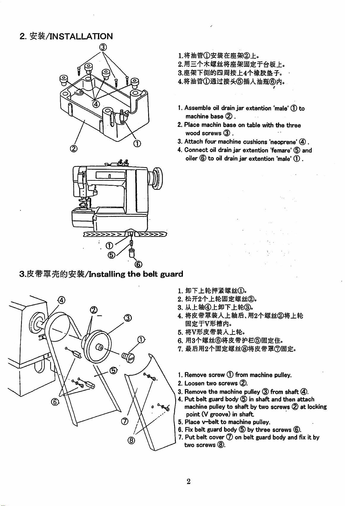
2.
SS/INSTALLATION
3.Jll^TiiJ6^Eg^i$±4't-ili^il:^-
3.R®5^65j$^/lnstalling
1.Assemble
machinebase
2.
Place
woodscrews
3. Attach four machine cushions 'neoprene' @ .
4. Connect
oiler
^
the
belt
guard
machin
oil
© to
oil
oil
drain
®.
base
@.
drain
drain
jar
extention 'male'® to
on
table
with
the
three
jar
extention 'femare'® and
jar
extention
'male'
® .
1.
mT±^wMm^®o
2.
3.
i^^±2i®±®T±$fe®o
4.
5.
7.
WLmm2^m&m^®m^^w®m^.
1.
Remove
2. Loosentwo screws
3.
Remove
4. Put belt guard body® in shaft and then attach
machine
point (V groove) in
5.
Place
6. Rx belt
7. Put belt cover® on belt
two screws
screw®
from
®.
the machine
pulley
v-belttomachine
guard
body
pulley®from
to shaft bytwo screws ® at
shaft
® bythree screws
®.
machine
pulley.
guard
pulley.
body
shaft
©.
and
®.
fix
locking
it by
Page 5
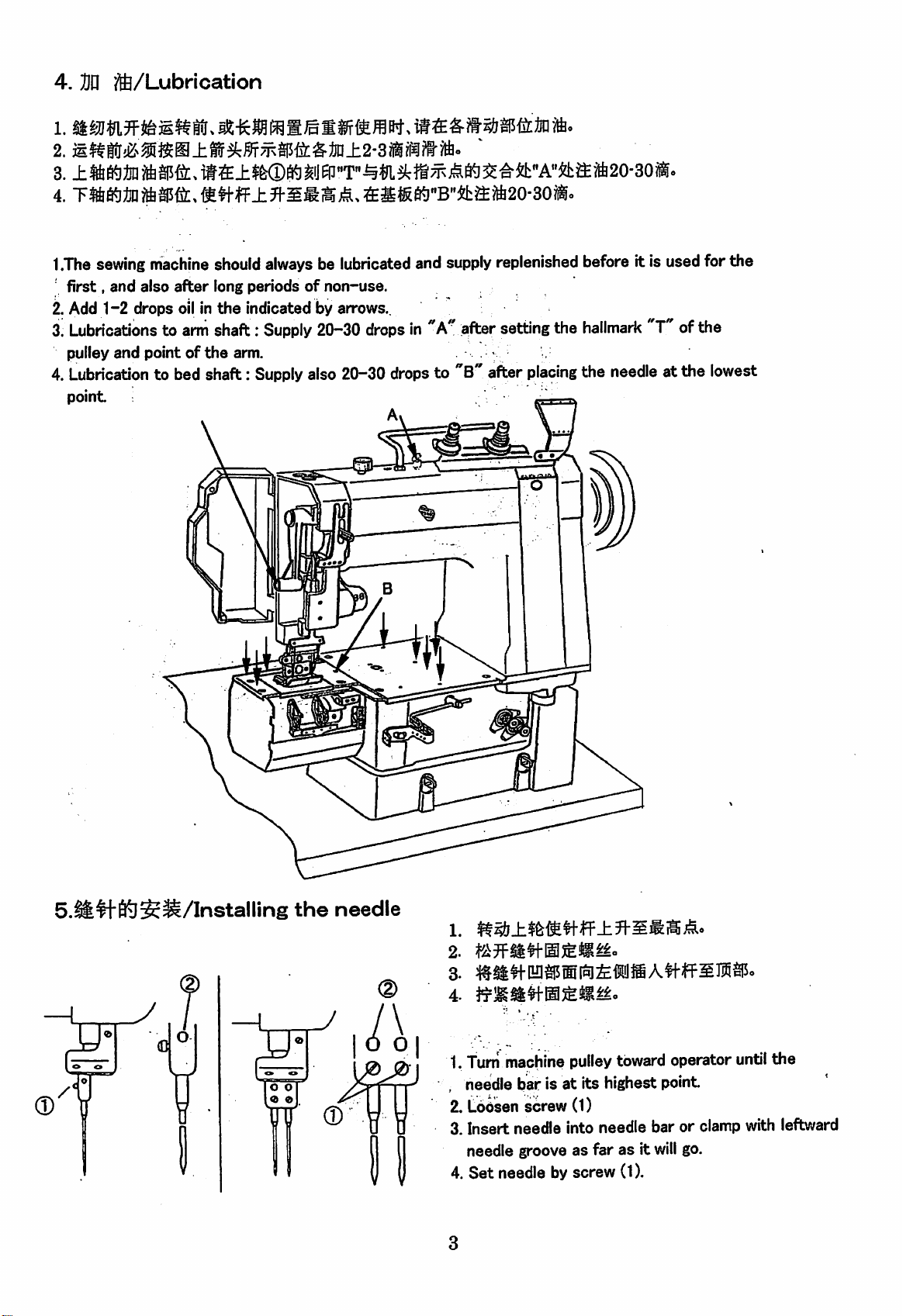
4.
Dn
?ft/Lubrication
1.
4.
T%S«lJO
1.The
'
first,
2. Add 1-2 drops oil in
3.
Lubricationstoarm
pulley and point of
4.
Lubrication
point
sewing
and
jftasffc.
fi!tfff4*ffiKl"B"&ffiift20-i
machine
also
after
to bed shaft:
should
long periodsofnon-use.
the
shaft:
the
always
indicated by arrows..
Supply
arm.
Supply
be lubricated and
20-30
also
20—30
supply
dropsin"A''after
drops
to "B after
Ai
replenished before it is used for the
setting
the
placing
hallmark
"T"ofthe
the needleat the lowest
S-lfe^fteS^/Installing
the
needle
1.
2.
3-
1. Turn machine pulleytoward operator until
, needle bar is at its highest point
2. Loosen
3. Insert needle into needle bar or clamp with leftward
needle groove as far as it
4.
Set
screw
needle by screw (1).
(1)
will
the
go.
Page 6
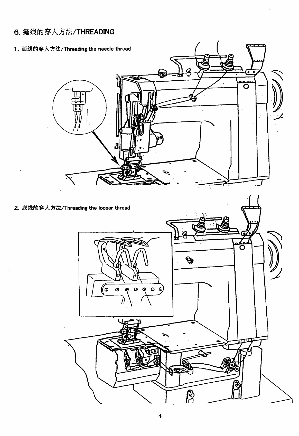
6.
^^Kl^AlJ^ft/THREADING
1.
®^6^^A;^^Ahreading
the
needle
thread
=U
2.
jlS^6^^A^^/Threading
the
looper
thread
a Q & o
(S>
M
Q> Q>
4
Page 7

7.ftE66i]ilSS/Adjusting the stitch length
Ji$fe^iB/Pulley
H'£&(mm)/Sutich
1.
Depress
operator
(locking position)
2.
Depress
3.
Hold
direction0to
4.
When
outward.
feed
until
button©locatedInthe center of
down,
andturii
desired
Caution:Never
recovers.
I
mark
length
regulating
plunger
decrease
plunger®.Continuetohold
enters
machine
notchInarm
pulley©toward
lengthofstitch.
lengthIsobtained,
operate
machine
Otherwise
other
A
6.4
release the
with
plunger®In
mechansim
8
4.9
plunger
shafteccentric.
machine
button
willbebroken.
bed
direction
and
depressed
C
3.4
down
Then
turn
until
button
Bto Increase
turn
plunger®toward
position
F
1
pulley©toward
and
D
2
turn
E
1.2
machine
plungers90degreestodirection
enters
length
notchInbed
shaft eccentric.
of stitch, or toward
directionAuntilitsprings
and
wait
until
the depressedbutton
A.
Page 8

Adjusting
Thread tension should be adjustedateach opeartion, as it may be changed depending on sewing cpndition
suchasthread,
material,
the
thread tension
etc.
1.To change needlethread tension,turn nut ® and®,as
may
be required.
2.Turn nut ® and ® toward direction Ato obtain more tension or toward direction B to
obtain
less
tension.
/Perfect
stitch
/Needle
thread
/ \ ^^^^VUnstable
t • •' J • •
1?
/Looper
thread
stitch
Page 9

9.ff
Mffi^fitfiJil^/Adjusting the presser foot pressure
U
C
B
r
1.
1.
Presser
2.Turn adjust screw ® toward direction Ato
increase
decrease
foot
pressureisadjusted
pressure
pressure.
and
toward
by thumb screw.
direction B
to
±.
y
tf^EE;tl6tlW^/A(Jiustingthe
OU
roller pressure
1.
1.
2.Turn adjust screw ® toward direction A to
Presser
increase pressure and toward direction B to
decrease
foot
pressure.
pressure
is adjusted by thumb screw.
Page 10

10.iM^3^iii®ilSS/Adjustingthe hight of the feed dog
When
the
of
throat
needle
plate,
barisat
and
the
its
lowest
topofthe
position, full
teeth
shouldbeparallel with
depthofteeth
1.
2.
•
3ll?l3^6^7R¥Tii!i
N 1.
should
throat
project
plate.
1.0 mm
above
upper
surface
6^7jc^'feSo
3.
•
Setting
1. To
tilt
2.
Loosen
height by screw
In
top
3.
When
the
heightoffeed
adjust
the
machine
nut ® and
height,
backonits
remove
Sfcrew
hinges.
®.
lowering
surfaceofthe
feed
dog
teeth
position,
downward.
correct heightis obtained, tighten screw ^
and nut (D securely.
•
Setting
the
horizontaloffeed
1.To obtain horizontal of feed
and
makeanadjustment
2. When
the
feed
pinch
screw© securely.
dog
position is
dog
throat
plate
and
@ and adjustfeed dog
depress
dog
dog,
set
the
loosen screw ©
correctly,
8
Page 11

11 .M^iT3^H!r®'feBtei^S/Adjusting the position offeed dog
Turn
the
between
machine pulley, place
throat
plate
and
the
feed
dog should be
feed dogatthe
setat1 mm.
nearest
position to operator and
1.
2.
1. To
adjust,
clearance
move
between
two screws ® and screw (D.
2. After the clearacne is
and screw ® securely.
feed
throat
dog
fixed,
the
clearance
until it
plate
makes
and
feed
correct
dog
tighten two screws ®
by
1 Adjusting
The
standard
clearance
between
the
sideofneedle
the
positionofneedle
and
1 mm when turned machine pulley toward operator and
of
feed
dog.
n-
0
—
—
—
—
—
o
o
.
bar
'
the
frontofneedle
the
needle point reached above upper surface
1.
1. Place together the letter
holeoffeed
"k"
dog
on machine pulley
and arm point (the longest stitch length)
2.
Loosen
or
3. Afterthe needle bar is
securely.
screw ® and move needle bar forward
backward
until
correct
position.
fixed,
tighten screw ®
should
be
Page 12

1
S.^^fi^USS/Adjusting
the
looper position
0.05-0.2%
iSSSO.05—0.2mm^&S®.
1.fe
JF«
iise.Jtmsss®-
2.
S#i-4(f^>lk®DSaW,
1.
♦aff2-f^#fH««M@.ifflSlSI^.
2.
5mm
i@SWit.--
1.
2.
Clearance
The standard clearance between groove of needle and looper point should be 0.05-0.2mm.
1.To
acQust
between
looper
looper
position,
and
needle
loosen screw ® and
move
looper
holder to get correct clearance.
2,Tighten the looperholderscrew ® securely
Clearance
The standard clearance between rightside of loopers and
front
1.To
2.After
Looper
When
needle during forward and backward movements of looper.
position.
acOust
loopers
position
pulley
between
looper
and
loop
deflector
loop
deflector shouldbe
clearance, loosen two screwsd)and moveloopers untilcorrect position.
are
fixed,
tighten two screws(D securely.
for
back
and
forward
is turned towardthe operator, looperpoint
movements
should
pass the same position in
1.5mm
when
groove
loopersare in
of
1.To
make
this adjustment, loosen screw (D
and,
then
change
the
position
of loopercan by adjusting the
tightness of two screws @ .
2. Tighten screw
(3)
and screws @ securely.
10
Page 13

WAUltON
1.
2.
Looper
2.5"^
Needle
J:$&f^f^^{S'Jlt^.
2.
• Lengthwise
When
armpoint 0 on
looper
of
the
1.Toadjust
the
looper
is
directlyonthe
settingoflooper
timingmark "T'^® on machine pulley and the
the
arm is placed together the
point
shouldbedirectly
needle.
the
position,loosen screw ® and move
forwardorbackward
oppositeofneedle
2. Tighten screw© securely
•
Settingofneedle
When
needle
needles
looper
their
turned
slightlyatthe
point
forward
toward operator.
And needles should
without
touching.
guard
guards
reaches
strokes
are
positionof2.5 mm
the
when
pass
55lilf4''Ci^2.5mm
opposite
until
position
properly
set.
centerofthe
machine
pulley
loopers closely,
the
looper
center.
they
needle
but
center
point
touch
before
on
is
Needle
guard
1.Toadjust
2.
11
and
obtained.
Tighten
turn
loosen
needle
set
needle
guards
screws @s ® securely.
guard
until
set
coirect
screws ®
positions
are
Page 14

1iMS/Adjusting
the height of needle bar
1.
1IS#|-fF«iii5g.
2.
Needle
iiS©,fi=Ka5t!li^®.
#f
ff
#S4
Looper
2~y%i
1
After looper position is
bar
against
side needle
1.Toadjust
screws 0 and move needle bar to correct position.
looper
eye
open
comes
fixed,
the height of the needle
shouldbepositionedsothat
2-3
mm above looper
face
plate
and
loosen
two
2.Tightentwo screws ® securely
upper
point
12
Page 15

15.iM^5F®J®SiStljM&/Adjusting the
loop
deflector
ftJnd^lBjltiifiSO.Smm'^l.Oinin.
0~1.0mm2E^o
0.5mni—1.0mm
Loop
deflector
0-1%
2.
iaiEe.yfS0S«M®.
•
Sidewise
When loop
should
left
sideofloop
feed
dog,
at
their
strokes.
•
Lengthwise
The
topofloop
upper
the
lowest
positioning
deflectorispositioned
beaclearance
and
right
extreme
positioning
deflector
sideofthe
position.
of
deflector,
sideofneedle,
forward
needle
correctly,
0.5-1.0
locatedonunderside
positionsontheir
shouldbe0 - 1.0 mm above
when
mm
when
needleisat
there
between
loopers
forward
its
1. Loosen two loop deflector screws (1) and move
deflectors
2. Tighten
until
correct
the
two screws (1) securely
positioning is
obtained.
the
of
are
13
Page 16

1
e.S^^pPKliJiS/Adjusting
0.2-0.5%,
the
spreader
aw.JSW-®jnse^/R5fea5;isiKirflPtiS
i@SESl.Smmo
2.
i@SEe,itlg0SS«®.
se^/nsi^sssiMw.fi^/R
.^^#f-^«®fti)lWPi®iiS:^0.2~0.5mm.
a^/Kilji^W-WlSIPtiHS^&0.5-t2mm.
0.5—2'%,
1.
2.
ifflSe.ifSOfeSM®.
•
Lengthwise
When
the
reaches
between
be
1.5
mm.
positioning
pointofneedle
upper
surfaceoflooper,
sideofneedle
1.To adjust loosen
spreader
2. Tighten
•
Turn
spreader
when
forwardorbackwardtoget
set
screw ® securely.
Sidewise
machine
positioning
pulley
point and
spreader
point
on
its
downward
the
clearance
and
spreader
set
screw ® and move
and
make
clearance
left
side of looper 0.2 - 0.5 mm
reaches
its
left
point
correct
side
stroke
should
position.
between
end.
•
Height
The
looperatthe
setting
spreader
point should
clearanceof0.5 - 2 mm
1.To adjust loosen two screws ® and move
spreader
2.
Tighten
14
upward or downward to
two screws (Dsecurely.
pass
above
get
upper
correct
side of
position.
Page 17

17.^^:§^KjiJiS/Adjustingthe thread
guide
n^atBfi5^s^^w.
ffi5^ffa)±?t-.
latiE.
mm
®ife,
• Adjusting
To
increase
the
needle
the
amountofthread
thread
guide
drawnatthe
top
of the needle bar stroke, raise take-up ® or loosen
guide screw and lower the guide
To
decrease
lowering
•
Adjusting
the
the
amount
take-up
the
looper
or
reverse
raising
thread
©.
the
the
guide
adjustment
guide.
i
by
1
8.l3i^J£^0^$S/Adjusting
the
timingbert
To
increase
thread
guide
the
amountofthread,
screw
and
looper
loosen
thread
looper
take-up
rod
screw. Andmove thread guide® and take-up rod
® to
the
ieft To decrease
adjustment
to
the
1.
3.
1. Turn machine pulley toward
barisat
2. Turn
allow markonsafety
opposite
3. Assemble timing
right
safety
by moving
its
highest
clutch pulley toward arm
the
rim on
belttoarm and
the
thread
point
cluth
the
machine bed.
amount reverse
guide
and
take-up
operator
until
shaft
pulley is
directly
safety
cluth
the
needle
until
pulley.
rod
15
Page 18

© SEIKO SEWING MACHINE CO.,
11-3.
Imado
TEU-i-S
FAX:+8l-3-3873-6596
E-Maii:seik0001@tctv.ne.jp
www.tctv.ne.]p/seik0001/
1<hoine,Taito-ku,
1-3-3872-6173,4(0verseas group)
Tokyo
111-8534,
LTD.
Japan
Part No.IM60710 (012001)
 Loading...