

Page 1
---
-
----
-
-------
--------
--
-----......;;
OPERATING
AND
PARTS
BElKO
.
BLIIDSTITCH
INSTRUCTIONS
BOOK
MACHINE
SERIES
CM3-L21
SEIKO
CM3-21
SEMI
S-EWING
TOKYO,
CM3-11
SELF-OILER
MACHINE CO., LTD.
JAPAN
Page 2

STANDARD
#10
Fine knit rayon
:r,
If
who
please write
NEEDLES
you
have any difficulty, do not hesitate
sold
you
this machine.
or
phone
us
If
unable to obtain satisfaction,
direct:-------------
SIZE
#15
#20
#25
#30
#35
#40
to
contact dealer
Fine knit wear
Fine knit jersey
Dresses and light fabrics
For
sportswear
For
heavy, hard material and coats
For
extra hard material
• SEIKO SEWING MACHINE CO., LTD.
11-3,
1-chome,
__
Phone:872-6171/6
Cable
Address: SEIKOSEWMCO
lmado,
Taito-ku,
Tokyo,
TOKYO
Japan
CM3-21
CM3-11
SERIES:
SERIES:
CM3-L21
CM3-P11
SEIKO
SERIES:
SERIES:
BLINDSTITCH
CM3-21L
CM3-11L
CM3-L21L
CM3-P11L
CM3-21M
CM3-11M
CM3-L21M
CM3-P11M
MACHINE
CM3-21H
CM3-11H
CM3-L21H
CM3-P11H
MODELS
CM3-21K(WITH
CM3-11K<NON
CM3-L21K
SKIP
<SKIP
SEMI-SELF
CM3-P11K
<PORTABLE)
SKIP
STITCH)
STITCH)
STITCH
OILER)
&
Page 3
INDEX
INFORMATION
PAGE
Needle Sizes .................................. Inside Cover
Models
Mounting
Oi I ing
Knee
in
our Line.......................... Inside Cover
on
Stand ....................................... .
Instructions ........................................ 1
Lifter Adjustment.................................. 2
Threading Chart ............................................ 2
Rib
Adjusting
to Needle.................................. 3
Stitch Ratio Lever............................................ 3
Testing and Changing Needle........................
How
to Sew.................................................... 5
·4
Stitching ........................................................ 5
Set
Rib
Shaft and
Rib
Connection............ 6 & 7
Needle Stroke ........................................ 6 & 7
Length of Stitch........................................
Adjusting
Looper
.................................... 8 & 9
6 & 7
PARTS
Rib
~--·····
.............................................. 1 0 &
Feed
Frame ........................................ 1 0 &
Main Frame ........................................ 12 &
PAGE
11
11
13
Main Shaft .................................................... 13
Front
Plates ..................................................
Presserfoot Assembly ....................................
Looper
Needle
Regulating
Rocker
Knee
CM3-
Rod
Assembly...................................... 16
Drive
Group........................................ 16
Dial
Group ...........................
Pin
Assembly......................................
~---·····
Lifter Assembly......................................
L21
Self Oiler........................... 19 & 20
11
15
17
17
18
MOUNTING MACHINE
1. Fasten machine to table
2.
screws
a.
b.
c.
The
from
direction
wheel
evenly, turning each a little
When
an
individual motor and clutch
is
employed, it
motor be rated
RPM.
On
all
outside diameter
tended for alteration,
diameter
When the machine
table, a
sible,
should
ING
The
ed for any installation
otherwise specified.
handwheel's direction of rotation
the operator.
pulley,
pulley.
4"
pulley
when
using
be mounted
THE
BELT.
maximum
when
as
looking
shown
using
felt pad. Tighten
at
a time.
is
recommended that the
at
I!J
HP
standard
pulley.
is
should
such
machine speed recommend-
It
by
and 1725/1750
models,
use
mounted
stands, the machine
TO
is
rotates
at
the arrow.
use
On models
a
21f2"
outside
on
be used. If
AVOID
3000
the face of the
a power
CROSS-
RPM,
is
in a clockwise
a Jlf2"
3. Either V-belting or round leather belting
be used.
over-heating and freezing of bearing
wheel.
Excessive
tension
of
belt
will
at
unit
in-
pos-
unless
away
may
cause
hand-
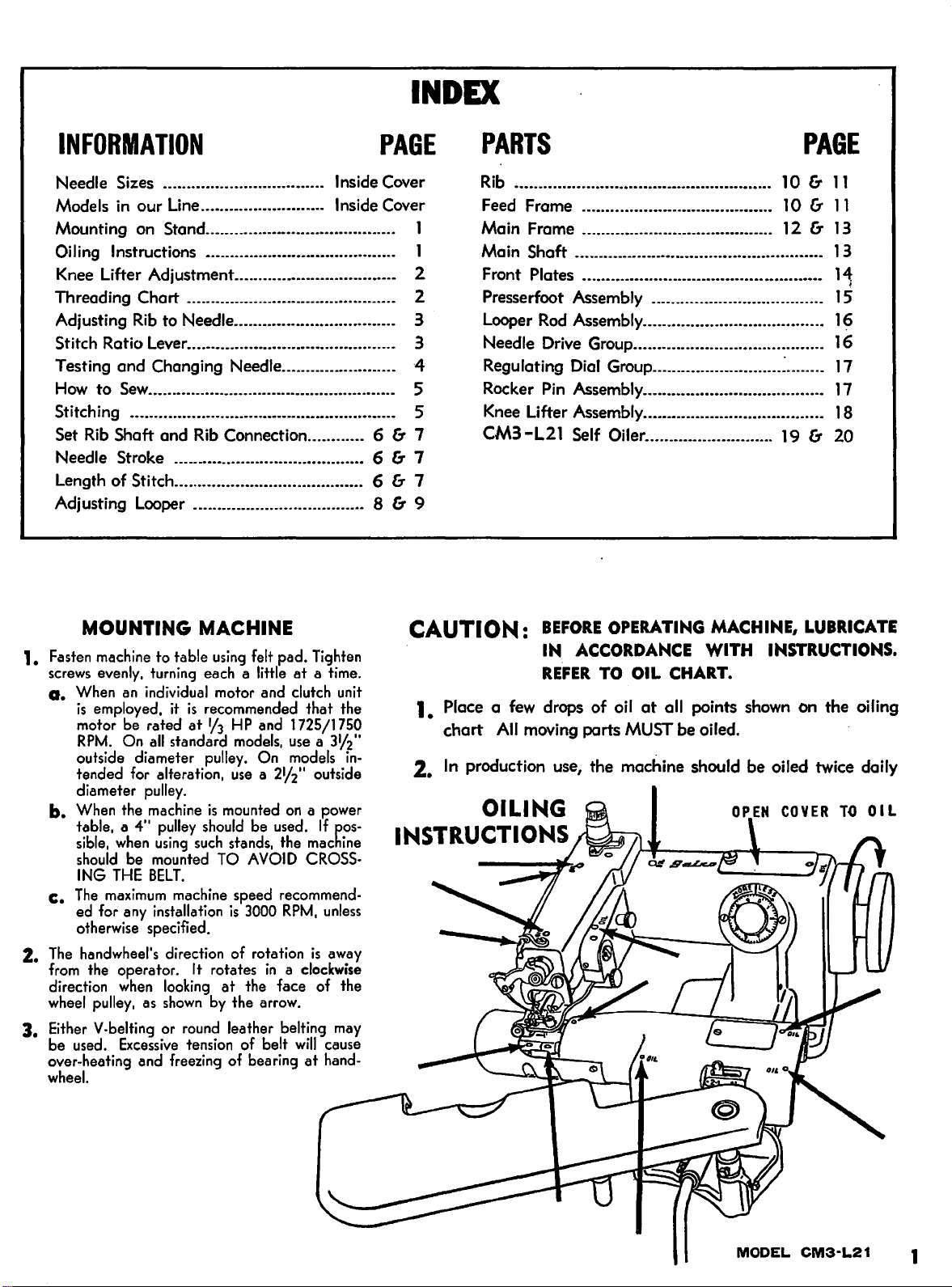
CAUTION:
BEFORE
IN
REFER
1. Place a
chart
2.
In
few
drops of
All
moving parts
production use, the machine should be oiled twice daily
OILING
INSTRUCTIONS
OPERATING
ACCORDANCE
TO
OIL
CHART.
oil
at
all points
MUST
be oiled.
MACHINE,
WITH
INSTRUCTIONS.
shown
LUBRICATE
on the oiling
MODEL
CM3-L21
1
Page 4
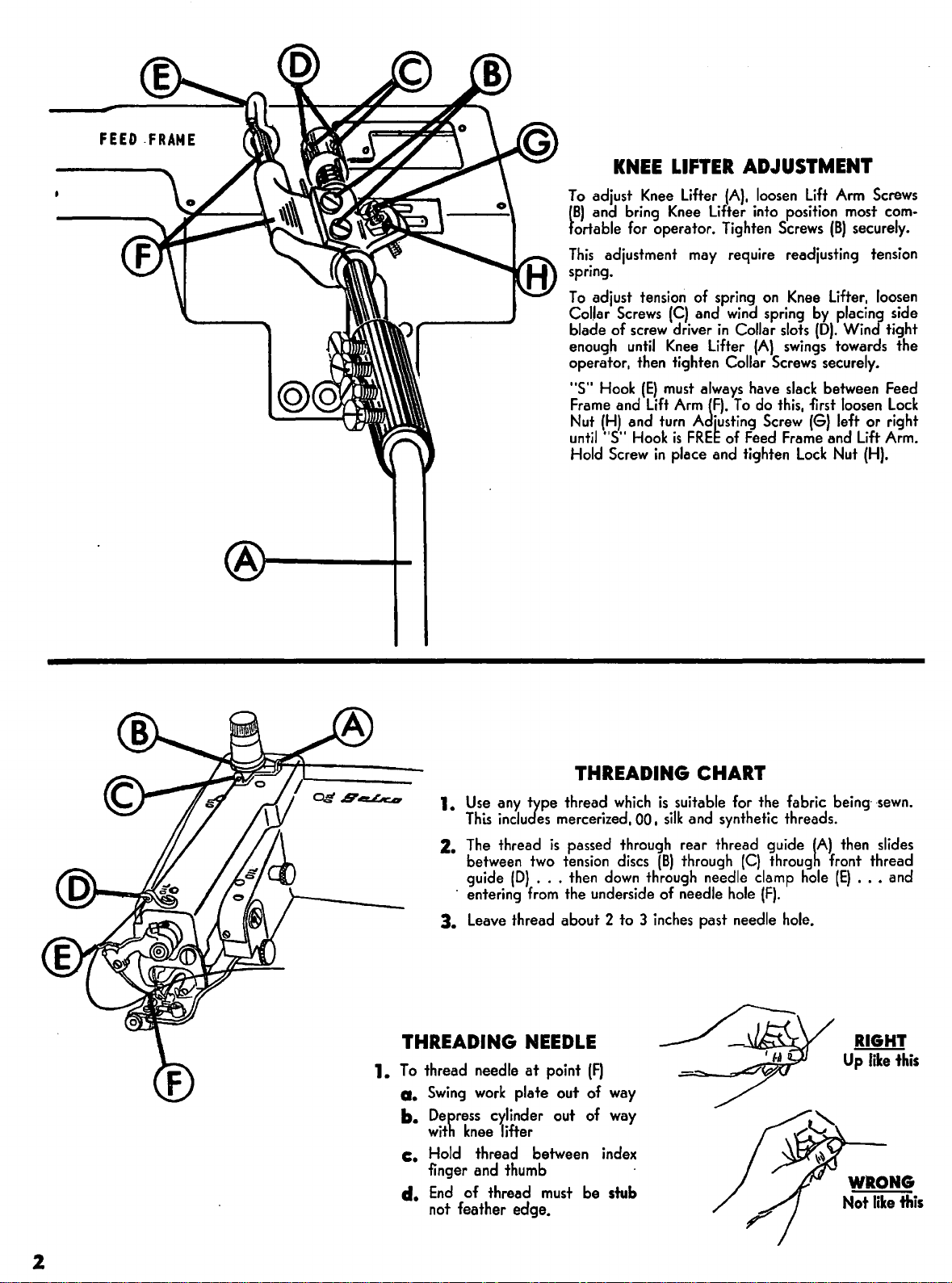
KNEE
To
adjust
(B)
and bring
fortable
This
adjustment
spring.
To
adjust
Col.lar
Screws
blade of
enough
operator, then tighten Collar
"S"
Hook
Frame
and
Nut
(H)
untii"S"
Hold
Screw
LIFTER ADJUSTMENT
Knee
lifter
(A),
Knee
Lifter into position most
for
operator. Tighten
may
require readjusting tension
tension
screw
until
(E)
and
Hook
of spring
(C)
and
wind
driver
in
Knee
Lifter
must
always
Lift
Arm
(F).
turn
Adjusting
is
FREE
of
in
place and tighten
Collar
(A)
have
To
Feed
loosen
Screws
on
spring
slots
swings
Screws
do
this,
Screw
Frame
Lift
Knee
slack
Lock
Arm
(B)
securely.
Lifter,
by
placing side
(D).
Wind tight
towards the
securely.
between
first
loosen
(G)
left or right
and
Nut
Screws
loosen
Lift
(H).
com-
Feed
Lock
Arm.
1.
2.
3.
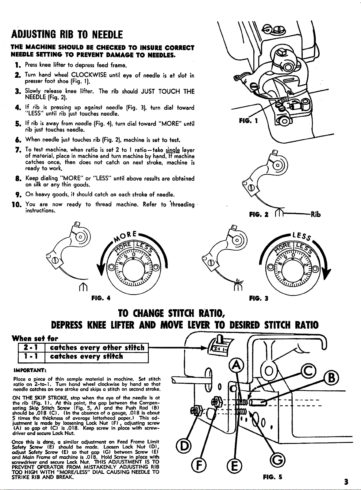
THREADING
1.
To
thread needle
a.
Swing
b.
Depress
with
c.
Hold
finger and thumb
d.
End
not feather edge.
Use
any
type thread
This
includes
The
thread
between
guide
· entering
Leave
two
(D)
...
from
thread about 2 to 3
NEEDLE
at
work
plate out of
cylinder out of
knee
lifter
thread between
of thread
THREADING CHART
which
is
suitable for the fabric
mercerized, 00,
is
passed through rear thread guide
tension
then
down
the underside of needle
point
(F)
way
way
index
must
be stub
silk
and synthetic threads.
discs
(B)
through
through needle clamp
inches
past needle
(C)
hole
being·
·sewn.
(A}
then
slides
through front thread
hole
(E)
..•
(F).
hole.
RIGHT
Up
like
and
this
2
Page 5
ADJUSTING
RIB
TO
NEEDLE
THE MACHINE SHOULD
NEEDLE
1.
2.
3.
4. If
5.
6.
7.
8.
9.
10.
SmiNG
Press
knee
lifter to depress feed frame.
Turn
hand
presser foot
Slowly
NEEDLE
rib
"LESS"
If
rib
rib
just
When
To
test
wheel
shoe
release
(Fig.
2).
is
pressing
until
rib
is
away
from
touches needle.
needle
just
machine,
of material, place
catches once,
ready to
Keep
dialing.
on
silk
or
On
heavy
You
are
then
work.
"MORE'' or
any
thin
goods, it
now
TO
PREVENT
CLOCKWISE
(Fig. 1 ).
knee
lifter.
up
just
touches needle.
needle
touches
when
in
machine
does not catch
goods.
should
ready to thread
instructions.
IE
CHECKED TO
DAMAGE TO
until
The
rib
against needle
(Fig.
4),
turn
rib
(Fig.
2),
ratio
is
set 2 to 1
and
turn
"LESS
..
until
catch
oR
each
machine.
INSURE
NEEDLES.
eye of needle
should
(Fig.
dial
toward
machine
JUST
3),
turn
is
set to test.
ratio-take
machine
on
above
next
stroke
by
hand.
stroke,
results
of needle.
Refer
CORRECT
is
at
slot
in
TOUCH
dial
..
MORE"
toward
sing!.§
If
machihe
THE
until
layer
machine
are obtained
to 'threading ·
is
FIG.
4
IMPORTANT:
Place a piece of thin sample material
ratio on
needle catches on one stroke
ON
the rib (Fig. 1 ) • At this point, the
sating Skip Stitch Screw (Fig.
should be
S times the thickness of average letterhead paper.> This
justment
(A) so
driver and secure Lock Nut.
Once this
Safety Screw
adjust Safety Screw
and
screwdriver
PREVENT
TOO
STRIKE
2-to-
1. Turn hand wheel clockwise by hand so
THE
SKIP
STROKE,
.018
(C).
Is
made by loosening Lock Nut
gap
at
(C)
Is
done, a similar adjustment on Feed Frame Limit
(E)
Main Frame of machine
and
secure Lock Nut. THIS ADJUSTMENT
OPERATOR
HIGH
WITH "MORE/LESS"
RIB
AND
stop when the eye of the needle
Un
the absence of a gauge, .018
is
.018. Keep screw
should be made. Loosen
(E)
so
FROM
BREAK.
and
5,
that
is
.0
MISTAKENLY
in
machine. Set stitch
skips a stitch
gap
A>
gap
(G) between Screw
18. Hold Screw
DIAL
on
between the Compen-
and the Push
(f)
, adjusting screw
in
place with screw-
ADJUSTING
CAUSING
second stroke.
Rod
is
Lock
Nut (D),
in
place with
NEEDLE
that
is
(B)
about
ad-
(E)
IS
TO
RIB
TO
at
FIG.
3
FIG. S
Page 6
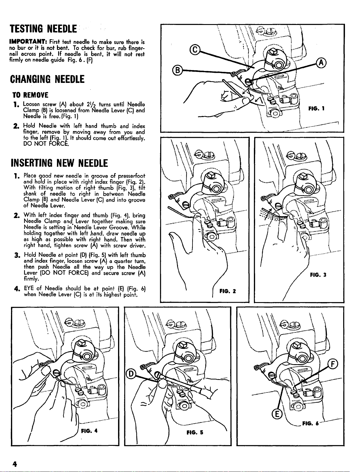
TESTING
'NEEDLE:
IMPORTANT:
no
bur or it
nail
across point.
firmly
on
CHANGING
TO
REMOVE
1.
Loosen
Clamp
Needle
2.
Hold
finger,
to the
DO
INSERTING
1.
Place
and
With
shank
Clamp
Needle
of
2.
With
Needle Clamp
Needle
holding
as
right
3.
Hold
and
then
Lever
firmly.
4.
EYE
when
First
is
not bent.
needle guide
If
NEEDLE
screw
(A)
(B)
is
loosened
is
free.
(Fig.
Needle
left
NOT
with
remove
(Fig. 1 ).
FORCE.
NEW
good
hold
high
index
new
in
place
tilting
motion
of needle to right
(B)
and Needle
Lever.
left
index
is
setting
together
as
possible
hand,
tighten
Needle
push
(DO
of Needle
Needle
at
finger,
Needle
NOT
Lever
test needle to
To
check
needle
by
Fig.
about
from
1)
left
moving
It
should
6 •
is
bent, it
(F)
21f2
Needle
hand
come
away
NEEDLE
needle
finger and
and
point
should
in
with
in·
with
loosen
FORCE)
groove of presserfoot
right
of right thumb
Lever
thumb
Lever
together
Needle
screw
all
(C)
left
with
(D)
screw
the
be
is
Lever
.hand,
right hand.
(A)
(Fig.
and
at
at
make
sure
for
bur,
rub
will
turns
until
Lever
thumb and
from
out
effortlessly.
index
finger
(Fig.
in
between Needle
(C)
and
into
(Fig.
making
Groove.
draw needle
Then
with
screw
5)
with
left
(A)
a quarter
way
up
the Needle
secure
point
its
highest point.
screw
(E)
there
finger-
not rest
Needle
(C)
and
index
you
and
(Fig.
2\.
3),
tirt
groove
4),
bring
sure
While
up
with
driver.
thumb
turn,
(A)
(Fig.
is
FIG. 1
~·--··-·-··-·.,._.,-~
FIG. 3
6)
\.
\
\
\.
\
~
\\
\\\
~
\
......
\
~
~~~_
·-v.•, \
......
\
~
\
4
Page 7
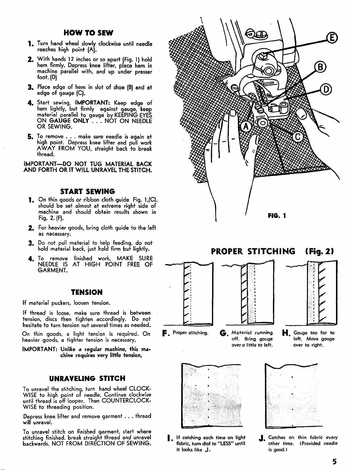
HOW
1.
Turn
hand
reaches
2. With
hem
machine
foot.
3.
Place
edge of gauge
4. Start
hem
material
ON
OR
SEWING.
5.
To
remove
high
AWAY
thread.
IMPORTANT-DO
AND
FORTH
wheel
high
hands
firmly.
parallel
(D)
edge of
sewing.
lightly,
parallel
GAUGE
...
point.
FROM
OR
START SEWING
1.
On
thin
goods or
should
machine
Fig.
2.
For
as
3.
Do
hold
4.
To
NEEDLE
GARMENT.
be set almost
and
2.
(F).
heavier goods,
necessary.
not
pull
material
remove
IS
TO
slowly
point
(A).
12
inches
or
Depress
but
Depress
IT
material
knee
with,
hem
in
(C).
IMPORTANT:
firmly
to gauge
ONLY
back,
finished
AT
make
YOU,
NOT
WILL
ribbon
should
HIGH
...
sure
knee
TUG
UNRAVEL
at
bring
to
just
SEW
clockwise
so
lifter,
and
slot
of
against gauge,
NOT
needle
lifter and
straight
MATERIAL
cloth
extreme right side of
obtain
cloth
help
hold
work,
POINT
until
needle
apart
(Fig.
1)
pface
hem
up
under presser
shoe
(B)
and
Keep
edge of
by
KEEPING
ON
NEEDLE
is
again
pull
back
to break
BACK
THE
STITCH.
guide
Fig.
results
guide to the left
feeding, do not
firm
but
MAKE
FREE
shown
lightly.
SURE
hold
in
at
keep
EYES.
at
work
l.(C).
in
OF
PROPER
FIG.
1
STITCHING (Fig. 2J
TENSION
If
material
If
thread
tension,
hesitate to
On
thin
heavier goods, a tighter
IMPORT
puckers,
is
loose,
discs
turn
goods, a
ANT:
chine
loosen
then
tension
light
l)nlike
tension.
make
sure
tighten accordingly.
nut
several
tension
tension
a regular
requires
thread
times
is
is
necessary.
machine,
very
little tension.
is
between
Do
as
needed.
required.
this
not
On
ma-
F • Proper stitching.
UNRAVELING STITCH
To
unravel
WISE
until
WISE
Defress
wil
unravel.
To
unravel
stitching
backwards,
the stitching,
to
high
point
of
thread
is
off
looper.
to threading position.
knee
lifter and
stitch
finished,
NOT
on
finished
break
FROM
remove
turn
hand
needle. Continue
Then
straight thread
DIRECTION
wheel
COU
NTERCLOCK-
garment
garment, start
OF
CLOCKclockwise
...
thread
where
and
unravel
SEWING.
I.
If
catching each time on light
f'obric, turn dial to
it looks like J .
G.
Material
off. Bring gouge
over
"LESS" until
o little
running
to
left.
J.
H.
Gouge too for
left. Move gouge
over to right.
Catches on thin fabric every
other time. (Provided needle
is
good.)
to
5
Page 8

PROPER
Turn
Handwheel clockwise until Needle
hand
edge
of
Needle Guide
SETTING
"A"
(Fig.
FOR
is
o.n
1),
RIB
the
DOWN stroke.
Rib
"B"
CONNECTION
When
should STOP
Needle reaches right
and
SHOULD NOT
MOVE
OPENING
If Rib does move,
Needle Point bock
screwdriver in place. Move Com
position, holding Needle in Position with handwheel while performing this operation. Tighten
Screw
If still
forward
sure to TIGHTEN
When
to
UNTIL
"B".
not
or
needle
desired position. Secure Screw. (See page 9 for closer detail
NEEDLE
"C".
make
Test
accuracy
correct, readjust by loosening screw
backward
is
in
POINT
the
following
to
right
hand
of
adjustment by repeating operation outlined in first paragraph.
as
needed
BOTH
some position
SCREWS
PASSES
edge
(R-1062) forward
and
"A" & "8"
TO
as
OVER
adjustment:
of
Needle Guide. Then loosen .screw
retighten Screw
SET
in
RIB
Fig. 1, loosen Screw (R-1117)
RIB
TO OTHER
First loosen Screw
or
backward until
"8"
again, change angle
11
•
"B
When adjusted satisfactorily,
before putting machine into operation.
SHAFT
of
SIDE
"A
in
Rib
OF
PRESSERFOOT
11
(Fig.
Rib
is
of
Fig.
3,
Shaft
if needed.)
2).
Bring
"B",
keeping
at
the
STOP
Com slightly
be
and
turn Rib
NEEDLE
Turn Handwheel clockwise, bringing Needle
the
Needle tip should be
To
attain
until Needle reaches desired position.
Loosen Screw
Indicator Notch
smaller
OR
POSITION
this, loosen Eccentric Ball Screw R-1118 (Fig.
R-1
072
in
the
number by
SHORTER, CHECK
OF
FEEDER
5/8"
to
11/16"
REGULATING
(fig.
5)
in
Stitch Regulating Collar
R-1
014.
The
larger
the
notch,
FEEDER
WHEN CHANGING
the
shorter
WITH
from the right side of Presserfoot opening (Fig.
LENGTH
the
LOOPER
STROKE
to
end
of
stroke
Pumber by
the
stitch. WHEN MAKING STITCH
AND
LENGTH
at
the
5)
and
turn
OF
STITCH
and
turn until desired number
the
notch,
PRESSERFOOT
OF
STITCH
right side.
Eccentric Ball (
the
longer
At
this point,
the
stitch.
AS
IT CHANGES
4J.
R-1
086)
is
by
The
LONGER
6
Page 9

FIG.S
t-1091
REGULATING
orR-1092
COLLAR
NOTCH
R-1014
IN
.,
Page 10

ADJUSTING
LOOPER
1. (FIG.
2.
To
Looper Rod (C)
3. (FIG.
Chain-Off
o
from
4.
Should Looper touch needle
wide
turn
counterclockwise.
5.
prong)
6.
prong
turn
at
7.
raise
1)
Loosen screw (A)
put
Looper in,
2)
Pin
sheet
of
paper
the
needle when needle
blade
of
Eccentric Block clockwise. If Looper
(FIG.
3)
If Looper touches
of
Looper
(FIG. 3 & FIG. 1) Should Looper be
of
Looper
Leaper
point (L)
(FIG. 2 & FIG.
or
lower your Loeper
be
at
point
Turn
Handwheel by
(E)
and
at
point
screwdriver
at
at
point
Rod
at
point (C) downwards, which
and
raise
3)
By
sure
you
(D).
clear
(G).
in
point
(L),
(L),
the
Looper
turning Eccentric Block
at
to
toke
out
Looper (B) - (Port
put
Looper in until shoulder
hand,
needle, being just above
The
is
at
the
or
Presser Foot
slot
of
Pres~er
turn
then
at
points (K)
carefully
long prong
limit
Eccentric Block
Foot or needle
Eccentric Block clockwise.
touching
you
must
point
and
of
stroke.
is
(K).
of
at
point
too
at
loosen
will
(J)
(L).
far
of
and
slowly. Looper
the
needle
the
Looper should
(G),
loosen screws (H)
at
(J)
. If Looper
obove needle,
at
point (
point (
K)
nut
(M)
clear
the
clockwise
#R-2200).
Looper touches shoulder
must
clear
about
the
thickness
be
about
is
hitting needle,
turn
Eccentric Block
K>
and
upper
and
needle touching
and
screws
short
prong
of
or
counterclockwise, it will
3/32"
and
part
Uong
short
(N).
Then
your Looper
of
the
of
use
With
ECCENTRIC
TURNING
8.
(FIG. 3 & FIG.
Eccentric Block
give you
9.
(FIG. 1 & FIG.
against
re-tightening screws (H) .
10. (FIG.
and
put
into
undercut
tightening
Needle Guide Screw
11. (FIG.
o
hair
(FIG.
BE
DOUBLY
LOOPER
the
desired clearance.
Looper Rod Carrier (T)
4)
When
in o new one. NOTE:
firmly, push Needle Guide securely towards screw, hold in position
5)
Feeder should
less
at
4).
BE
SURE
BLOCK,
ROD, you
2)
For Looper
U)
can
2)
If this
Needle Guide (U) (port
neck
of
(V).
point
(X).
SURE
LOOPER
FEEDER
you
RAISE
RAISE
To
be moved from left
is
necessary,
and
When
screw
(V).
be
below Presser Foot o
CLEARS
SCREWS
or
LOWER
one
side
clear
Chain-Off
to
be
sure
does
not have
#R-1238)
replacing Needle Guide, slide
Hold
together
FEEDER
<Z>.
ARE
Looper on BOTH
and
you
LOWER
Pin
(Q)
right by loosening screws
that
Looper Rod.Carrier Pin (S)
any
play
becomes grooved or broken, remove
and
screw on Presser Foot.
maximum
AT
POINT
SECURED
of
FIRMLY.
and
left
3/32"
(Y).
SIDES.
the
.other
Presser Foot
or
"U"
at
side.
(H).
right. Secure by
of
Needle Guide
Just
and
point
at
This will
is
flush
before
tighten
<W)
and
fR),
8
Page 11

1
1
1
1
1
1
1
1
1
1
1
1
1
1
1
1
1
1
4--
32
FIG.
\ "
1
''10
4
-
1
1
1
1
1
1
1
1
1
ftG. 2
fiG· 1
Page 12

RIB
FOR
VARIOUS
MODELS AS INDICATED
Model
CM3-21L
CM3-11L
CM3-L21
CM3-P11L
I
R-6036
L
Rib
FEED
GROUP
R-1205 Window Plate
R-1
030
R-1
087
R-1
088
R-1
069
R-1159 Screw - Spring Link Lock
R-11
R-1146 Nut - Feed Frame Limit Screw Lock
GROUP
R-1
029
R-11
R-1202 Skip Regulating
R-1
028
R-1203 Stud - Skip Regulating Lever
R-1332 Screw -
Model
CM3-21M I
CM3-llM
CM3-l21M
CM3-P11M
FRAME
I
Screw - Window Plate
Rib Shaft Bushing - Left
Rib
Shaft Bushing - Right
Set Screw - Platten Bracket Pivot Stud
04
Screw - Feed Frame Limit
2
Nut
- Skip Stitch Compensating
05
Screw - Skip Stitch Compensating
Spring
Washer
Skip Regulating Lever Stud-Lock
Rib
CM3-21H l
R-6010
(CM3·21)
- Skip Regulating Lever Stud
CM3-11H
CM3-L21H
CM3-Pl1H
Model
Rib
R-6015
Model
CM3-21K l
CM3-11
CM3-l21K
CM3-P11K
K
R-6032
Rib
GROUP
RIB
R-
R~
R-1164 Stud R-1161
R-1
R-1162
GROUP
R-1166
R-2451
R-2450
R-2400
R-2401
R-1244
R-1167
R-1168
R-1114
R-1171
R-1021
GROUP
R-1212 Cylinder
R-11
3
-See
1163 Crank -
1117 Screw -
Rib
076
Screw -
Rib
R-1
076
Screw -
4
Stud-
Platten Bracket - Left
Platten
Platten - Left
Platten.- Right
Screw Nut
Nut
Screw - Platten Bracket Limit
Spring - Platten Bracket
Spacer - Platten Bracket
5
01
Screw- Cylinder
Chart
Shaft Collar - Left
Shaft Collar - Right
- Platten to Bracket Attaching Screw
- Platten Bracket Limit Screw-Lock
Top
of
Page
Rib
Shaft
Rib
Shaft Crank - Clamp
Rib
Shaft Crank
Rib
Shaft
Collar-Clamp
Rib
Shaft Collar-Clamp
Platten Bracket Pivot
Bracket-
Platten
Right
to
Bracket - Attaching
For
Seiko
Models
Use
same
CM3-21,
IMPORTANT
Semi-Self-Oiler
CM3-
part
but
L21
numbers
add
Series
prefix
as
''L'·
10
Page 13

R-1212
I
GRouP
sl
Rl
8 -
TOP
OF
SEE
PAGE
.J
,.
\ : I
\ :
.,
CHART
! i R-1117
10 ; i R
j
,.,
L,
_,
•,
\
GROUP
31
I
1163
-
~
R-11 1
6
R-1166
0)
P.-110 1 I
R-2400 R-2401
R-1167®·~~
----
----
R-1171"-
._
~
R-2451 R-1·114
~a-~~~
R-1244~~
• ------
·~R-1168
• R-1171 -
I
GROUP
41
4
2
~OR-1167
~
-~
• R-1168
~
I
I
I
i
I
-®---1
R-1021
~
R-1114
FEED
CM3-21
IMPORTANT
Ordinarily, machines have this narrow
cylinder, but thicker
as
illustrated above
without any
additional charge.
R-1101
~',~.
R-2455
cylinder No.
is
installed on order
~~F="'::'-=-=~=-=-
R-2456
R-1211
""-.....;a,...--
FRAME
SERIES
----
FEED
GROUP
NARROW
R-1166
R-2455
R-2456
R-241 0
R-2409
R-1244
R-1167
R-1172
R-1021
R-1056
R-1055
R-1132
R-1262
R-1212
R-11
R-1069
CYLINDER
CM3-21
Stud-
Platten - Left
Platten - Right
Screw
Nut
Spring - Platten Bracket
SpacerSpring Post
Stop Post
Screw Nut
Cylinder
01
Screws - Cylinder
Set
Platten Bracket Pivot
Platten Bracket - Left
Platten
Bracket-
Platten
- Platten
Platten Bracket
Platten Bracket-Limit
- Platten Bracket Limit-Screw Lock
Screw-
MACHINES
SERIES
Right
to
Bracket
to
Bracket Screw
Platten Bracket Pivot Stud
11
Page 14

MAIN
R-1010~
R-1011.
FRAME
GROUP
For
Seiko
Models
Use
·same
CM3-21,
IMPORTANT
Semi-Self-Oiler
CM3-
part
but
L21
numbers
add
prefix
Series
as
"L "
I
GROUP
31
R-5001
R-108~
R-10098
R-1083
R-1084
~
_
R-5002
__,
S E
I
GROUP
IIICIDI
21
R-1096
T
I
\
.
R-1081
R-I0
68R
l
---~
R-ll20R
~
R-12
R-124~
R-10
66
R.-l02::i
I
89
I
GRO
UP 1 I
12
Page 15

·~----MAIN
GROUP
R-1
R-1
R-1
RM-1
RM- 1
R-1
R-1120R Set
R-1
R-1096
R-1240
R-1094
R-1289
GROUP
R-5002
R-1084
R-1082
R-1083
R-1009
R-1085
R-1
R-1010
R-1080
R-1070
066
093
025
088
087
068R
081
2
011
1
ShaftSet
Pin - Regulating Fork-Pivot
Main
Main
Belt Guard
Cover
Screw - Cover Plate
Eccentric Pin
Screw - Eccentric Pin Set
Screw-
Tension Assembly,
Thread
Tension Post
Tension Discs
Cover
Spring
Ratchet
Nut
Front
Screw-
·FRAME
Feed Frame Rocker
Screw - Feed Frame
Shaft
Shaft
Screw-
Plate
Eccentric Block
Guide
Thread
Front
GROUP
Bushing - Right
Bushing -
Belt Guard
Complete
Guide
Thread
Guide
Shaft
left
MAIN
GROUP
R-1044
R-1129
R-1069
GROUP
RT-5003 Group 2, Fitted &
R-1
R-1071
R-1062
R-1120
GROUP
R-1043
R-1121
R-1069
GROUP
RT-5004
R-1014
R-1331
R-1331A
R-1013
R-1086
R-1072
1
Main
GearScrew - Skip Stitch Drive Gear
2
015
Rib
Connection Lever
Screw - Rib
Rib
Connection .Eccentric
Screw-
3
Handwheel
Screw - Handwheel Set
Screw - Handwheel
4
Group
Needle
Set
Screw - (Cone Point) Feed Eccentric
ScrewNeedle
Eccentric
Screw - Needle Connection
SHAFT
Shaft
Skip Stitch Drive
Connecting Lever
Rib Lever Eccentric
4,
Fitted
and
Feed Eccentric
(Flat) Eccentric
Shaft
and
Ball Stud
GROUP
lapped
Set
and
Lapped
Feed Connection
(CM3-21)
(Cone Point)
Set-lock
Set
Clamp
GROUP
I
GROUP
RT-5004
3
R-5001
R-5019
Side
Screw - Side Cover
~tl
FITTED-LAPPED
R-1072
I B
i
_!..-
Cover
COHPLETE
I
GRouP
--~1
.
R-1134
R-1014
sl
R-1132
-~J
MAIN
I
SHAFT
GROUP
1 I
GROUP
R-1134
R-1132
5
GROUP
Eccentric
Screw-
Eccentric Ball Guard
Ball Guard
RT-5003
FOR
CM3-21
SERIES
I
GROUP
31
13
Page 16

~ALL
EXCEPT
R-1200
MODELS CM3-21
"K"
R-1051
I
GROUP
1 I
THESE
PARTS
SWING
BRACKET
FOR
ALL
PLATES
COMPLETE
BRACKET
FOR
ALL
USE
PLATE
ASSEMBLY
CM3·21
No.
1·5180
AND
MODELS
FRONT
GROUP
R-5180 Complete Plate
R-5180-6 Complete Plate
R-1200 SwingPiate
R-1200-6 Swing Plate (618-6 Series)
R-5015 Support Shaft
R-1051
R-1228
R-1052
R-1053
R-1227
R-1230
R-1229
R-1103
R-1230
R-1229
R-11
R-1225
R-1048
R-1226
R-1049
R-1
051
PLATE
1
Screw- Pivot Pin-Lock
Bracket - Swing Plate-Support
Screw - Stop
Washer
Stop
Washers (Flat) -Swing Plate Support Bracket Screw
Washers (Lock) -Swing
Screw - Swing
Washer
Washer
03
Screw- Swing
Pin - Swing
Retaining Ring - Swing
Collar - Swing Plate Pivot Pin
Set Screw- Swing
Screw - Swing Plate Pivot Pin-Lock
GROUP
(618and808)
Plate
- Stop Plate Screw
Plate
(Flat) -Swing Plate Support Bracket Screw
(Lock) -Swing Plate Support Bracket Screw
Plate Pivot
AND
and
Bracket Assembly (618
and
Bracket Assembly (618-6 Series)
Assembly
Plate Support Bracket
Plate Support Bracket
Plate Pivot Pin Collar
SUPPORT
Plate Support Bracket Screw
Plate Pivot Pin
14
BRACKETS
and
808)
~
R-1051
R-1103
Page 17

SPECIAL
THAT
GUIDE
IS
HARD
R-2600NT
FOR
618NT -618NT -808NT
COMPLETE
CLOTH
ASSEMBLY
AND
TO
GUIDE
GAUGE
KEEP
UNCURLED,
I
GROUP
WHERE
31
NECESSARY
SUCH
AS
NYLON
FOR
MATERIAL
TRICOT.
PRESSERFOOT
®R-1054
GROUP
Model
L
M
H
K
Presser
completefassy.
44A
44C
44C
44C
foot
Rib
6036
6010
6015 2506
6032
Shoe
498
49C
49C
Cloth
2600
2600
2600
2600
guide
Cylinder
1212
1212
NON
1212
15
Page 18
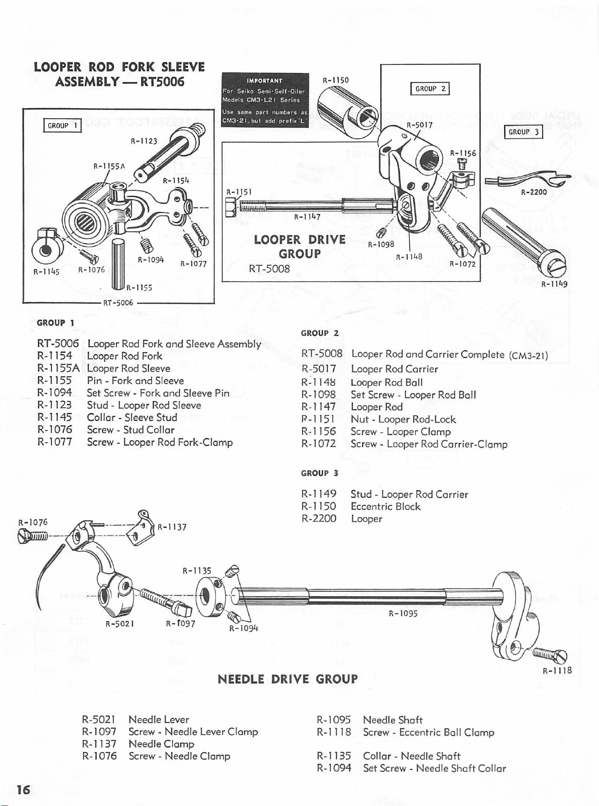
LOOPER ROD FORK
ASSEMBLY-
I
GROUP
RT5006
SLEEVE
For
Sc1ko
Models
Use
same
CM3-21.
IMPORTANT
Sem•·Self·Oder
CM3-
L21
part
numbers
but
add
Seroes
pre
lox L
as
I
GROUP
21
I
GROUP
31
'-------
GROUP 1
RT-5006
R-1154
R-11
R-1155
R-1
R-1123
R-1145
R-1076
R-1 077
55A
094
RT-5006
Looper Rod Fork
Loo
per
Lo
ope
- F
Pin
Set Screw - Fork
Stud -Lo
Collar
-----....J
and Sleeve
Rod Fork
r Rod Sleeve
ork and Sleeve
and
ope
r Rod Sleeve
- Sleeve
Stud
Screw - Stud Collar
Screw -Loo
per
Rod F
R-10
77
Assembly
Sleeve Pin
ork
-Clamp
LOOPER
GROUP
RT-5008
R
-114
7
DRIVE
GROUP 2
RT
-5008
R-50
R-114H
R-1098
R-114
R-1151
R-1156
R-1072
GROUP 3
17
7
R-1
098
48
R-11
Looper Rod
L
ooper
Looper Rod
Set
Screw-Looper Rod Ball
and
Carrier Complete
Rod Carri er
Ba
ll
Looper Rod
Nut-
Looper Rod-Lock
Loop
er Clamp
er
Rod
Screw - Loop
Screw-
R-1072
Car
rier-Cl
~
(CM3-21)
amp
R-2200
R
-114
9
R-1076
~-
--
R- 5
R-5021
-10
97
R
R-1
137
R-1
076
-,
021
Needle Leve r
Screw -
Needle
Screw-
Needle
Cla
Needle
R-1149
R-
115
R-2200
R-1135
---ft1\~ES
~
-
;;;;;e::::==:~~
~;"''J
R-f097 R-1094
Stud-Looper
0
E
ccentric Block
Loop
er
R-
Rod
1095
NEEDLE DRIVE GROUP
mp
Lever
Clamp
Clamp
R-1095
R-1118
R-
1135
R-1
Need
Screw-
Collar - Needle
094
Set
le
Shaft
Eccentric Ball
Screw - Needle
Carrier
Shaft
Shaft
Clamp
Collar
16
Page 19

R-5039
I
r---
I
!'
0 -
I
GRouP
GROUP
R-1181
~
5
GROUP 1
R-1183
R-1185
RR-1
R-1094
R-1180
R-1179
R-1
GROUP 2
R-5013
R-1201
R-1069
GROUP
REGULATING GROUP
41
R-50
11
R-1022
~I
I I R-1
'-·
1025
026
069
R-1193
'
~
024
--
--R
Support Arm - Com Roller
Regulating Fork
Pin - Regulating F
Pin - Roller Support
Screw - Roller Support Arm Pivot Pin-Set
Com Roller
Pin - Com Roller Support
Screw-
Skip
Ecc
Pin - Skip
Screw-
R-1
o23
-
5012__j
ork
-Piv
Arm-Pivot
Com
Roller Support
entric
Gear
Assembly ICM3-2 1 Series)
Eccentric
Skip Eccentric Gear
Gear
~~-
R>-----!··0
R-
'1
195 I
- CM3-21 Series
ot
Pin-Set
a0:
~--
R-I09
GROUP
GROUP
21
··
4
R- 1201
1
R-1069
GROUP 3
R-5018
R-
1223
R-1222
R-5010
R-
110
9
R-5039
R-1
039
GROUP 4
R-5011
R- 1
193
R- 1
022
R-1 18 1
GROUP 5
R-5012
R-1195
R:1023
R-1024
Reg
ulating
Dial Assembly
Regulating Dial
Regulating Dial Screw
P
late
Face
Screw
- Regulating Dial Assembly
Di
al
and
Screw - Dial
Push Rod Assembly
Push Rod I
Cotter Pin
Spring - Push Rod (
Push Rod Assembly
Push Rod I
Cotter
Pin
Spring - Push
Shoe
and
Guide Pin Asse mbly
Ratchet Assembly
and
Ratchet Assembly-Lock
V4
"I
3fa
" )
Rod ( 3;8")
V4
")
R-5016(CMJ-71)
FITTED t
-1
R
LAPPE~
072
RT
-5 111
FEED
::~;
-2100
·2101
1\ \
~-~~:it:::
·-···-·
:,
~
I········
~~
;
&_R-1076
£~~
R-
111
9
~----~-=,.,
!
R-1145
'
'·
R-1138
R-
1138
R-
109
1
R-1092
R-1072
R-5016
R-
I 14 5 Collar - Rocker Pin
R-
1076
R-21
00
R-2 101
R-
1119
-59138
RT
DRIVE GROUP
F
eed
Lever
Stitch Regulating Collar
Stitch Regulating Collar F
Screw-Stitch Regulati ng Collar-Clamp
ocker
Pin Assembly
R
Screw - Rocker Pin Collar Feed
Dog
Feed
Dog Fine, 20Te
Sc;ew - F
( 1
091
eed
Dog
& I 1381
eth
Fitted
or
all
"'K•
Clamp
to Inch.
and
Lapped (CM3-21)
17
Page 20

GROUP
R-1060R
R-5060
R-1120
R-1008
R-1035 Screw- Lift Arm Adjustment
R-1
R-1059
R-1036
R-1334
R-1060C
R-10600
GROUP
061
1
Knee Lifter
Lift Arm
Screw
Nut
SpringCollar
Set Screw
Feed Frome
Knee Lifter
Knee Lifter
l
Rod
Shaft
- Lift Arm Clamp
-·Lift Arm Adjusting Screw-Lock
Knee Lifter Rod-Return
- Knee Lifter
- Knee Lifter
"S"
Rod
Rod
Rod
Rod
Hook
Sleeve
Sleeve Screws
Collar
.,
,,
II
II
,,
,,
,,
,,
R-5060
R-10608
R-1208
R-1037
GROUP
R-5020
R-1191
R-1177
R-1184
R-1169
Knee Lifter
Knee Pad
Knee Pod Screw
3
Spring
Main Spring
Screw - Main
Nut-
Main Spring Adjusting
Nut-
Spring Link Assembly-Retaining
Rod
Link Assembly
Spring Link
GROUP
KNEE
GROUP
GROUP
R-1060R
1
LIFTER
2
R-10608
GROUP
3
SPRING
GROUP
18
LINK·
@@)
t
~
R-1169
FEED
FRAME
R-1037
'
Page 21

SEIKO
SEMI-
SELF-OILER
MODELS
CM3-L21
SERIES
IMPORTANT
For
SEIKO
Models
Use
with
add
r·--------
CM3-L21
same
CM3-21
p r e f i x
Semi-Self
part
models
"L
''
---,
I
I
I
I
I
I
Series.
numbers
but
Oiler
as
I
I
I
I
I
I
L-------
-------------
.J
~l-~2
~L-~3
1
ll-~4
19
Page 22

IMPORT
ANT-
Use
same
For
part
SEIKO
numbers
Semi-Self-Oiler
as
with
CM3-21
models,
Models-
but
add
prefix "L".
CM3-L21
·sERIES
L-800
L-801
L-802
L-803
L-804
L-805
L-806
L-807
L-808
L-809
L-810
L-81
L-810B Screw -
L-811
L-812
L-813 Wick
Felt
PadBaseNippleHolder -
Screws Spring
Oil
Bottle
Cover - Main Frame
Gasket - Cover
Screws -
Oil
Vibrator
OA
Spring - Oil Vibrator
Screws - Splasher
Wire Loop
E
xamp
PARTS
ON
Base
Machine
Base
Oil
Bottle
Holder
Clamp - Bottle Holder
Cover
Oi
I Vibrator
Holder - Wick L-813
-Bushing
Needleshaft
1
e:
Needleshaft(CM3-L21
LISTED
SEIKO
(CM3-21
models}
models)
BELOW
ARE
USED
SEMI-SELF-OILERS
Part
No.
Part No.
R-1
LR-1
095
095
EXCLUSIVELY
(CM3·L21 MODELS).
Loop
L-814
L-815
L-816
L-817
L-818
L-819
L-820
L-821
L-822
L-824
L-825
L-826
L-827
L-828
L-829
Wire
Wick Wire
Wick - Skip Eccentric Gear
Wire
Wick - Skip Stitch Gear Drive
Wire
Screws- Wire
Nipple-
WickWire
Wick - Looper
Glass -
Wire
Wick-
Holder- Wick L-815
Rib
Connection Lever
Loop
Holder- Wick L-817
Loop
Holder- Wick L-819
Holder- Wicks
Loop
Wick L-824
Main Shaft
Loop
Holder - Wick L-826
Oi
I Gauge
Loop
Holder - Wick
Drain From Side Cover To Base
Rod
Holders
Carrier
829
20
.·,
~-.
. '
:.
Page 23

Printed
in
Japan
--:--
 Loading...