

Operating
Instructions
For
CH
Series
CH-2B
CH-2B/DF
CH-6B
CH-7B
CH-8B
CH-2-RF
<f
h
SEIKO
SEWING
MACHINE
CO.,
LTD.
TOKYO•JAPAN
Specifications
of
CH
Types
Sewing
speed;
Needle
type:
Number
of
needle:
Sewing
type:
Hook:
Bobbin:
Thread:
Feed
system:
Stitch
length:
Presser
foot:
Presser
lift:
Thread
take-up:
Thread
take-up
stroke:
Needle
bar
stroke:
Bed
shape:
Bed
size:
Working
space:
Net
weight
(head
only)
JIS
classifications:
Motor:
Motor
pulley:
V
Belt:
Applications:
Max. 800
s.p.m.
(Max.
sewing
speed
willbechanged
by
the
models
and
applications.)
DD X 1
#24-25,
standard
#24
(Needle
type
may
differ
from
the
above
types
according
to
the
threadstobe
used
and
the
materials
being
sewn.)
Single
needle
Lockstitch
Oscillating
large
hook
CH
Type
(240 x 30.3
width)
Cottonorsynthetic
fiber
(SB) Needle,
upper&lower
feed,
reverse
feed
(7B)
Needle,
Lower
feed,
reverse
feed
(6B)
Lower
feed,
reverse
feed
(2B)
Upper&lower
feed,
reverse
feed
(2B/DF)
Upper&lower
feed,
reverse
feed
(Capableofintermediate
shirring)
Max.
10mm
(SB) Alternating
foot
(walking
foot&presser
foot)
(7B)
Flat
foot
(6B)
Roller
footorflat
foot
(2B) Alternating
foot
(walking
foot&presser
foot)
(2B/DF)
-
ditto
-
20mm
by
knee
lifter
(10mmbylever)
Cam
type
90.5mm
51mm
Cylinder
bed
(tubular
type
820)
820X600mm
200mm
x
400mm
65Kg
LS3
400W.
4P
clutch
motor
6O0(5OHZ)
5O0(6OHZ)
M62
Suitable for
sewingofshoes,
bags, satchels, sport-goods,
luggages,
ultra
heavy
materials.

Contents
1 Lubrication 1
2 Needle 1
3 Thread 1
4 Insertion
and
Removal 2
5 Winding the Bobbin Thread 3
6 Upper Threading 3
7 Tension of Bobbin Thread and Needle Thread 4
Adjusting Needle Thread Tension 4
Adjusting Bobbin Thread Tension 4
8 Pressure of Presser Foot 5
9 Adjustmentof Stitch Length 5
10 Timing of Thread Tension Releasing Mechanism 6
11
Removal of Shuttle Race Body 6
12 Adjusting on
the
Each Points 7
(A)
Adjusting Needle Position Against Needle Hole of 7
the
Feed
Dog
{7B & 8B
Types)
(B)
Adjusting of Feed Dog Height 7
(C)
Adjusting theForward and Backward Position of q
Needle
BarFrame
(D)
Timing of Needle and Hook 8
Positioning of
needle
and
tip of
the
hook 9
Adjusting
the
height of needle bar 9
Adjusting
the
position of
the
tip of hook 9
Clearance between needle
and
tip of hook 9
Each timing for up/down strokes of
presser
10
foot
(2B & SB
Types
only)
13
CH-2B/DF
11
a. Use of
the
Differential Feed Mechanism 10
b. Adjusting Upper Feed Length Against Lower Feed 11
Length
14
CH-2-DF
Adfusting
Upper
Feed
Length
11
Adfudting
Lower
Feed
Length 12
Positioning
Upper
Feed
Dog 13
Adjustment
14
Adjusting
Up/Down
Amount
of
Upper
Feed
14
Positioning
presser
Bar
15
1
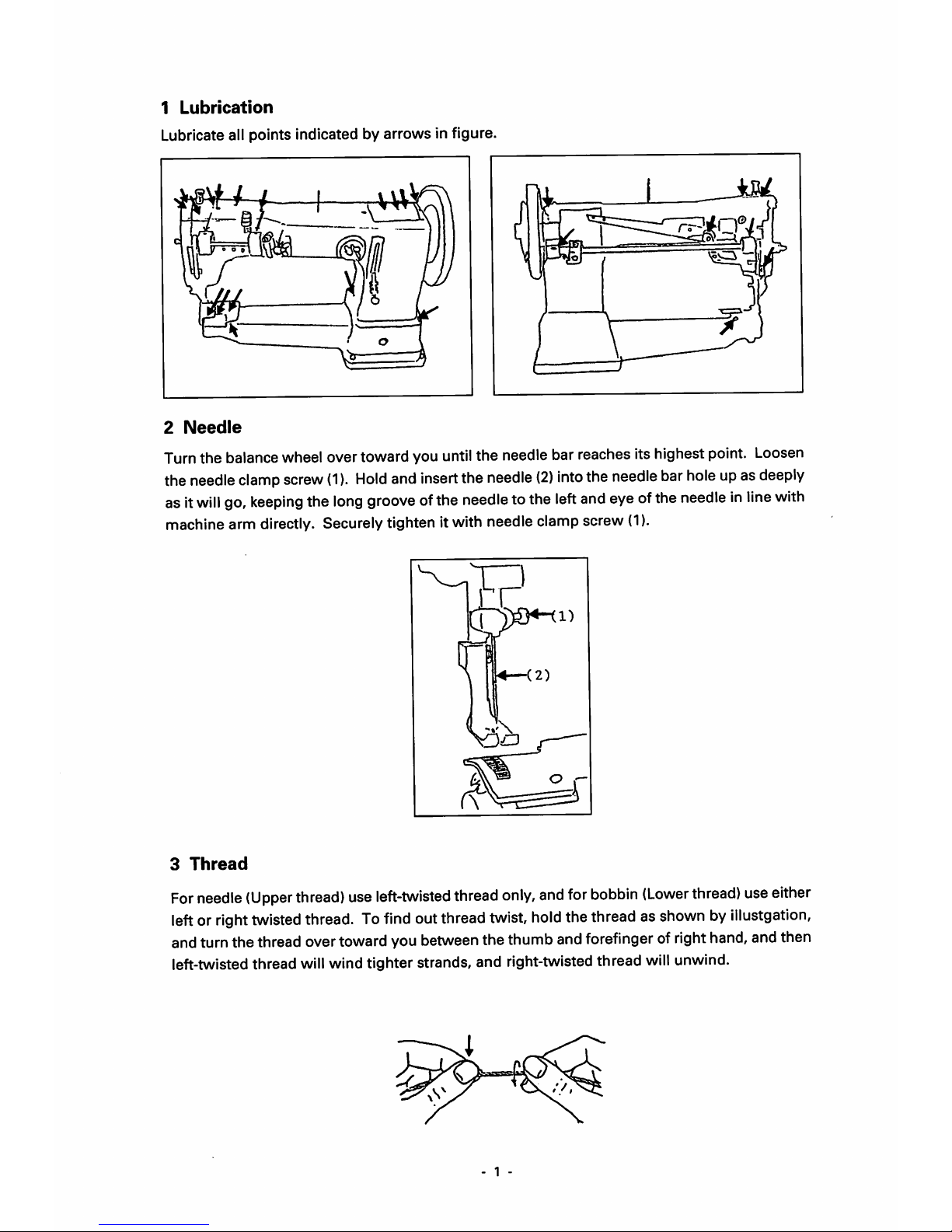
Lubrication
Lubricate all points indicated by arrows in figure.
2
Needle
Turnthe balance wheel over toward you untilthe needle bar reaches its highest point. Loosen
the
needle
clamp
screw
(1).
Hold
and
insert
the
needle
(2)
into
the
needle
bar
holeupas
deeply
asit
will
go,
keeping
the
long
groove
ofthe
needle
tothe
left
and
eyeofthe
needleinline
with
machine arm directly. Securelytighten itwith needle clamp screw
(1).
3
Thread
For
needle
(Upper
thread)
use
left-twisted
thread
only,
and
for
bobbin
(Lower
thread)
use
either
leftorright
twisted
thread.Tofind
out
thread
twist,
hold
the
threadasshownbyillustgation,
andturnthe thread overtowardyoubetweenthe thumb andforefinger of
right
hand,andthen
left-twistedthread
will
wind tighter strands, and right-twistedthread
will
unwind.
1 -
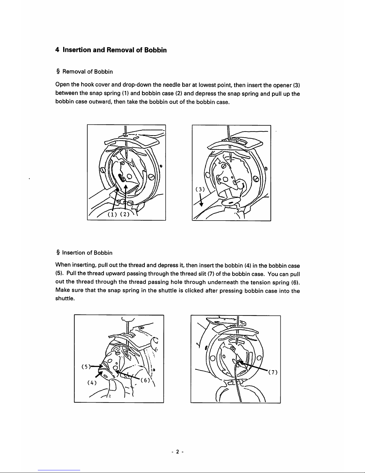
4
Insertion
and
Removal
of
Bobbin
§
RemovalofBobbin
Open the hook cover and drop-down the needle bar at lowest point, then insert the opener (3)
between the snap spring
(1)
and bobbin case
(2)
and depress the snap spring and pull up the
bobbin
case
outward,
then
take
the
bobbin
outofthe
bobbin
case.
§
InsertionofBobbin
When inserting, pull
out
the
thread
and
depress
it,
then
insert
the
bobbin (4) in
the
bobbin
case
(5).
Pull
the thread upward passing through the thread slit
(7)
of the bobbin case. Youcan pull
out the thread through the thread passing hole through underneath the tension spring (6).
Make sure
that
the snap spring in the shuttle is clicked after pressing bobbin case into the
shuttle.
2 -

5
Winding
the
Bobbin
Thread
Bobbin winding should be made by the following order.
(l)Spool pin—
(2)
Thread guide
(arm)—(3)
Needle
thread tension thread guide — passing
through the clearance betweentwo tension discs —(4)
Needle
thread tension thread guide
(5)Bobbin (winding several times) — (6)Move
the
bobbin winding lever.
A
Winding
volume
shouldbeadjusted
bythe
screw
(7)
and
positioning
ofthe
moving
lever
(6).
6
Upper
Threading
Upper threading should be made by the following order.
(I)
Spool
pin
—(2)
Thread
guide
ofthread
tension
—(3)
Clearanceoftwo
tension
discs
—(4)
thread guideofthreadtension
—(5)
Thread
controller-*^disc
wind
a time—
(6)
Thread
guide
(7)
Tensionspring —
(8)
Thread take-up —(9)Thread guide, face plat —(10) Needlecramp
(II)
Needle
\|1^(1)
- 3 -
 Loading...