

Page 1

PARTS CATALOGUE / TECHNICAL GUIDE
Cal. 6T63A
[SPECIFICATIONS]
Cal. No.
Item
Interval of hands movement
Driving system
Additional function
Loss/gain
Regulation system
Gate time for rate measurement
Power
supply
Battery No.
Battery voltage
Battery life
Number of jewels
1/19
Crown
operation
Normal position
1st click position
2nd click position
Current consumption
Coil resistance
1 second
0 jewel
Stepping motor, 2 pieces
• Stopwatch function
60-minute stopwatch in one second increments.
• Second hand stop function
4002054 (COIL BLOCK A)
1.45 - 1.65 K
Ω
Use 10-second gate.
SEIKO SR936SW
Nil
1.55 V
Approx. 3 years
6T63A
• 3 hands (hour, minute, and
small second hand)
• 24 -hour indicator
• Date indicator
4002055 (COIL BLOCK B)
1.65 - 1.85 K
Ω
Free
Date setting(clockwise)
Time setting, hand position adjustment / resetting the circuit
Monthly rate: Less than 20 seconds (worn on the wrist at the tempera-
ture between 5 and 35)
• Diameter
Outside: Ø 30.8 mm Casing: Ø 29.0 mm
• Height: 5.1 mm
Movement : Less than 2.70 μA
Circuit block: Less than 0.70 μA
Page 2

SPECIFICATIONS
2/19
Cal. 6T63A
Cal. 6T63A has a new structure employing one crown and two buttons. The construction of chronograph
mechanism is based on Cal. 8R28 mechanical chronograph watch by using the one-piece 3 pointed reset
hammer. While other Swiss-made watches are using separate hammers which require an assembly and
adjustment of the hammers, the one-piece hammer design realizes maximum durability and stability of
the component and easier maintenance. It is also equipped with the self-alignment function for all counting
hands to return to zero positions instantaneously.
This is the multi-display analogue watch featuring a stopwatch function.
●
The time is indicated by the 24-hour, hour and minute hands, and a small second hand.
●
The stop watch can measure up to 60 minutes in one second increments. After 60 minutes,
it will stop automatically.
● Measurement performance
Displays the elapsed time with the 2 designated STOPWATCH hands.
Measures up to 60 minutes in one second increments.
● Button operation (Crown position: Normal position)
Button A: START/STOP
Button B: RESET
1. STOPWATCH FUNCTION
Cal . 6T63A
a b c
Hour hand
Minute hand
STOPWATCH 1/5-second hand
STOPWATCH minute
hand
Small second hand
a: Normal position
b: First click
c: Second click
24-hour hand
A
B
CROWN
When pushin g th e re se t bu tton
the HAMMER OPERATING LEVER
B moves automatically to
ke ep ap propr iate bal ance of th e
HAMMER position.
CHRONOGRAPH
COUPLING LEVER
HAMMER OPERATING
LEVER A
HAMMER OPERATING
LEVER B
HAMMER HAMMER
HAMMER OPERATING
LEVER B
FE ATUR ES
START
RESET
Page 3
SPECIFICATIONS
3/19
Cal. 6T63A
After installing the battery, pull out the crown to the second click position. And then follow the
instructions below to correct the hand positions and set the time.
NECESSARY PROCEDURE AFTER BATTERY CHANGE
Pull out to the second click position when the small second hand is at
the 60 seconds position. The small second hand stops on the spot.
Crown
Push back in to the normal position in accordance with a time signal.
Crown
Watch starts moving with 2-second interval for 10 seconds. Wait until it moves with
1-second interval.*
* Do not move the crown before it ends.
Button B
Press Button B for longer than 2 seconds.
The STOPWATCH minute hand turns a full circle.
● Standard measurement
Button A
START
→
Button A
STOP
→
Button B
RESET
● A ccumulated elapsed time measurement
Button A
START
→
Button A
STOP
Button A
STOP
→
Button B
RESET
→
Button A
RESTART
…→
Restart and stop of the stopwatch can be repeated by pressing button A.
●
Measurement functions
Accumulated elapsed time measurement and split time measurement are available.
Page 4
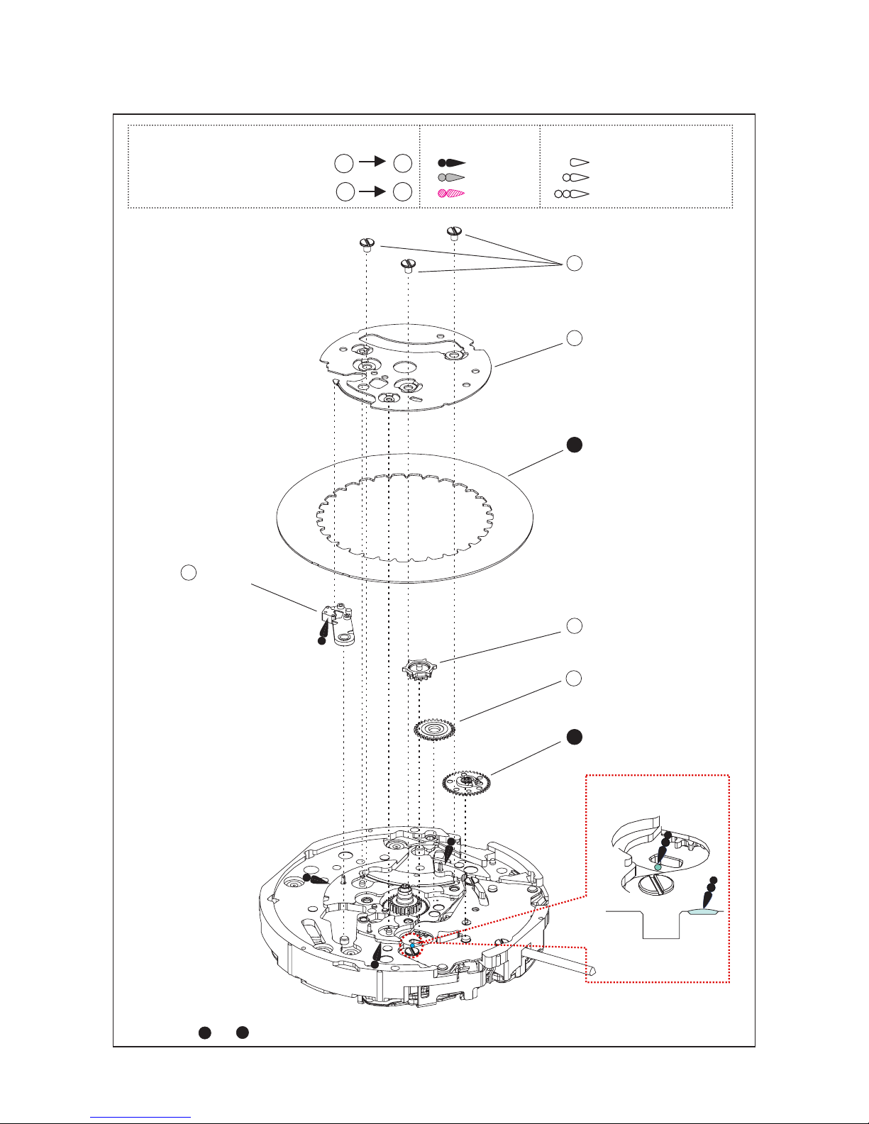
Cal. 6T63A
PARTS LIST
4/19
DAT E I NDI CATOR
MAINTAINING
PL AT E SC REW
0012354
1
2
3
4
5
6
7
DAT E I NDI CATOR
MAINTAINING
PL AT E
0808052
DATE DIAL
0878***
DAT E J UM PER
0810019
DATE CORRECTOR
WHEEL
0806002
INTERMEDIATE
SMALL HOUR HAND WHEEL
AND PINION
0817048
SMALL HOUR HAND WHEEL
0157***
[ Cross section ]
7
3
For parts and , please refer to the page 10.
Disassembling procedures Figs. : 1 61
Reassembling procedures Figs. : 61 1
AO-2
Type of oil Oil quantity mark
NORMAL QUANTITY
AO-3
S-6
LIBERAL QUANTITY
SMALL QUANTIT Y
Page 5
Cal. 6T63A
PARTS LIST
5/19
HOUR WHEEL
0273***
8
9
SWITCH LEVER
HOLDER SCREW
012354
10
11
12
14
13
SWITCH LEVER
HOLDER
0837005
SWITCH LEVER A
4450017
SWITCH LEVER B
4450018
DATE CORRECTOR
SETTING
TRANSMISSION
WHEEL B
0962013
DATE CORRECTOR
SETTING TRANSMISSION
WHEEL C
0962891
For parts , please refer to the page 10.
8
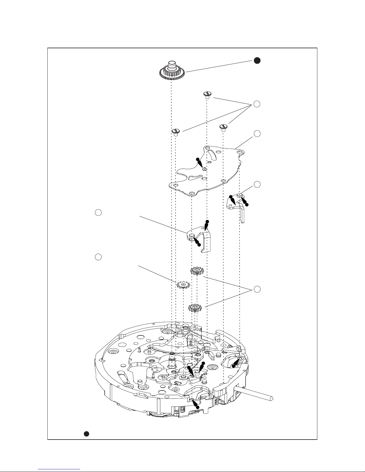
Page 6

Cal. 6T63A
PARTS LIST
6/19
*1
*1
*2
*2
15
SWITCH SPRING SCREW
0016121
17
SECOND COUNTING
WHEEL FRICTION
SPRING
0353018
18
CHRONOGRAPH
BRIDGE
0190007
16
SWITCH SPRING
4250***
19
CHRONOGRAPH
COUPLING LEVER
0581007
25
TRAIN WHEEL
STOP LEVER
0894002
26
HAMMER OPERATING
LEVER A
0587004
20
HAMMER OPERATING
LEVER B
0587006
HAMMER
0585013**
15
SWITCH SPRING SCREW
0016121
21
SECOND
COUNTING
WHEEL
0888***
22
POSITIONING
ARBOR
0685002
23
MINUTE
COUNTING
WHEEL
0740***
24
For parts , please refer to the page 10 and 11.
For parts and , please refer to the page 10.
For parts , , , , and , please refer to the page 12 and 13.
22
16
25 26
24
2019 21
Page 7

Cal. 6T63A
PARTS LIST
7/19
For parts , please refer to the page 12 and 13.
27
LOWER PLATE FOR
CHRONOGRAPH BRIDGE SCREW
0016121
28
LOWER PLATE FOR
CHRONOGRAPH BRIDGE
0186002
29
CIRCUIT BLOCK SPACER
44 0814 9
30
CIRCUIT BLOCK
4004253
31
BATTERY CONNECTION (-)
4270336
35
SECOND COUNTER
INTERMEDIATE WHEEL
AND PINION
0885003
38
COIL BLOCK SCREW
0012354
39
COIL BLOCK A
4002054
40
STEP ROTOR
4146063
41
STAT OR A
4239063
34
MINUTE COUNTER
INTERMEDIATE WHEEL
AND PINION B
0886006
36
COUNTER
INTERMEDIATE WHEEL
AND PINION
0886004
37
MINUTE COUNTER
INTERMEDIATE WHEEL
AND PINION A
0886005
42
FIFTH WHEEL AND
PINION
0701015
32
TRAIN WHEEL BRIDGE
0125316
33
MINUTE COUNTER
INTERMEDIATE WHEEL
AND PINION
0886007
*1
28
Page 8

Cal. 6T63A
PARTS LIST
8/19
43
RESET LEVER
4455006
50
TRAIN WHEEL
SETTING LEVER
0391028
51
COIL BLOCK SCREW
0012354
52
COIL BLOCK B
4002055
53
STEP ROTOR
4146063
54
STAT OR B
4239064
57
SETTING
LEVER
0383891
58
YOKE
0384024
60
CLUTCH
WHEEL
0282452
61
DATE CORRECTOR
SETTING
TRANSMISSION
WHEEL A
0962012
59
WINDING STEM
0351177
44
THIRD WHEEL
AND PINION
0231043
45
FOURTH WHEEL
AND PINION
0144 002
46
MINUTE WHEEL
AND PINION
0261026
47
SETTING WHEEL
0016121
48
CENTER WHEEL AND
PINION BRIDGE
0016121
49
CENTER WHEEL
AND PINION
0221***
55
FIFTH WHEEL
AND PINION
0701015
56
SECOND WHEEL
0240***
*1
*1
49 56 59
For parts , and , please refer to the page 10.
Page 9

Cal. 6T63A
PARTS LIST
9/19
●
Tools and consumables required for disassembling/reassembling
• Movement holder
UNIVERSAL MOVEMENT HOLDER (S-682)
• Watch oils
SEIKO watch oil AO-3 (or Moebius A) and AO-2 (or Moebius F)
AO-3
AO-2
S-6
Page 10

TECHNICAL GUIDE
Cal. 6T63A
10/19
●
How to find the correct parts, if not determined by 4 digit caliber number
Following par ts are determined based on the design of watches, such as hands height, dial
color, and design of cases. Please refer to the SEIKO WATCH PARTS CATALOGUE in order to
choose corresponding parts.
3
DATE DIAL 0878***
59
WINDING STEM 0351177
* For screw down crown models, the stem is assembled to the crown and is not available
separatelly
7
SMALL HOUR HAND WHEEL
8
HOUR WHEEL
16
SWITHCH SPRING
22
SECOND COUNTING WHEEL
24
MINUTE COUNTING WHEEL
49
CENTER WHEEL AND PINION
56
SECOND WHEEL
Please refer to the following table in order to find the correct part number of each wheel
according to the hand installation height. The numeral 2 or 4 is printed on the DIAL.
7 SMALL
HOUR HAND
WHEEL
8 HOUR
WHEEL
16 SWITHCH
SPRING
22 SECOND
COUNTING
WHEEL
24 MINUTE
COUNTING
WHEEL
49 CENTER
WHEEL AND
PINION
56 SECOND
WHEEL
2
0157012 0273038 4250035 0888017 0740002 0221087 0240018
4
0157013 0273042 4250054 0888019 0740003 0221092 0240019
Page 11

TECHNICAL GUIDE
Cal. 6T63A
11/19
Push the "A" on the SETTING LEVER
gently(refer to the pic ture on the
right) in order to disengage it from
the SETTING STEM. Then pul out
the crown with the stem completely.
FOR UNIT'S DIGIT properly.
REMARKS ON DISASSEMBLING AND REASSEMBLING THE MOVEMENT
●
How to remove the SETTING STEM before dismantling the movement
Crown position: normal (=0) position.
A
●
How to remove or install the battery
1) Remove the hook of the switch spring's battery clamp.
2) Insert the battery sideways, and have the hook of the switch spring's battery clamp catch the
main plate.
Battery clamp
Main plate
1) When Removing
2) When Installing
16 Switch spring
●
Remarks on installing the battery
1) Af ter t he bat t er y is re plac e d
battery is reinstalled following
the repairing procedures, be
sure to touch the AC terminal
of circuit block and the switch
spring with conductive tweezers
to reset the circuit as illustrated.
Tweezers
Page 12

TECHNICAL GUIDE
Cal. 6T63A
12/19
●
Remarks for the lubrication
Hammer
21
There must be oil within the range of the arrow.
Lower plate for chronograph bridge
28
Note
*1: Oiling should be done on the
pointed spot of marked place.
*1
*1
*1 *1
Switch spring
*Oiling spot and spring set ting position.
16
*2
*3
*3
*2
Chronograph coupling lever
19
Setting position
Switch spring
16
*Oiling should be done on the contact spot of the spring and the pin.
Hammer operating lever B
20
AO-2
Type of oil
Oil quantity mark
NORMAL QUANTITY
AO-3
S-6
LIBERAL QUANTITY
SMALL QUANTIT Y
Page 13

TECHNICAL GUIDE
Cal. 6T63A
13/19
●
Remarks for setting position of the spring of chronograph function
Lower plate for
chronograph bridge
28
Hammer operating
lever A
26
Train wheel stop lever
25
Chronograph coupling
lever
19
Hammer operating
lever B
20
Hammer
21
*2
*3
*4
*1
*1
*2
*3
*4
Setting position
●
Remarks for setting position of the SWITCH LEVER A and B
*1 *2
Chronograph
coupling lever
Hammer operating
lever A
Switch spring
Switch lever B
Switch lever A
Switch spring
*2
*1
Enlarged view
Switch lever B is set between the switch
spring and hammer operating lever A .
Switch lever A is set between the switch
spring and chronograph coupling lever.
Page 14

TECHNICAL GUIDE
Cal. 6T63A
14/19
REMARKS ON INSPECTION AND MEASUREMENT
1. To measure the current consumption for the whole move-
ment, connect the ( -) probe to the battery connection ( -)
and (+) probe to the other metal part of the movement,
such as battery clamp or circuit block cover.
* When measuring the current consumption using the
SEIKO digital multi-tester (S-860), use the range of 40 μ
A of SUPPLY V (= 1.55 V) & GATE TIME (2 S).
2. Connect the AC component to the positive terminal for 2
seconds until a short circuit occurs to reset the integrated
circuit.
3. After the integrated circuit is reset, wait approximately for
10 seconds until a stable measurement is obtained, and
then read the measurement.
4. Make sure the read value is less than 2.7 μ A.
●
How to measure the current consumption for the whole movement
●
How to measure the current consumption for the CIRCUIT BLOCK alone
1. To measure the current consumption for the CIRCUIT
BLOCK alone, connect each probe to the appropriate
positive (+) or negative (- ) input terminal of the CIRCUIT BLOCK (please refer to “Structure of the CIRCUIT
BLOCK” below) .
* When measuring the current consumption using the SEI-
KO Multi-Tester S-860, use the range of 4 μ A of SUPPLY
V (= 1.55 V) & GATE TIME (2 S).
2. Repeat the same procedures as 2. and 3. of measuring
current consumption for the whole movement above.
* When measuring the current consumption for the circuit
block alone, be careful not to damage or deform the pattern of the circuit block.
3. Make sure the read value is less than 0.7 μ A.
Page 15

TECHNICAL GUIDE
Cal. 6T63A
15/19
●
Value checking – coil resistance (coil blocks)
Check the resistance of each coil block if they are within the range in the following table.
1.45 KΩ ~ 1.65 K
Ω
1.65 KΩ ~ 1.85 K
Ω
COIL BLOCK (A)
COIL BLOCK (B)
4002054
4002055
[Structure of the CIRCUIT BLOCK]
Input terminal (+)
Input terminal (-)
Output terminal(hand moving)
Crystal unit
Output terminal(CG)
C=MOS=IC
Page 16

TECHNICAL GUIDE
Cal. 6T63A
16/19
Operation
Function
Checkpoint
Pull out the crown
to the 2nd click
and push it back
in to the normal
position. Repeat
the same several
times.
Setting mechanism
- switching the
function of the time
setting
Make sure that it
has a click at each
position and the
stem is not pulled
off.
Pull out the
crown to the 1st
click, then turn it
clockwise.
Hands installation
Make sure that the
hour and minute
h a n d s m o v e
smoothly (without
touching each other
of touching the
surface of the dial or
inside of the glass).
Make sure that
the day changes
smoothly.
Calendar mechanism
- correcting the day
Make sure that the
date changes when
the hour and minute
hands pass around
midnight.
Calendar mechanism
- date change
●
Function check
Press button A
to start the stopwatch.
Press button A
again to stop the
stopwatch.
Press button B
to reset the stopwatch.
Stopwatch
mechanism
Make sure that the
Stopwatch hands
start/stop smoothly.
Make sure that the
Stopwatch hands
are reset to the
“0” position.
Pull out the crown
to the 2nd click,
then turn it.
Setting mechanism
- hour and minute
hand setting
A
B
A A B
Start Stop Reset
Page 17

TECHNICAL GUIDE
Cal. 6T63A
17/19
●
Water resistance test
Check the water resistance according to the designated specification of the watch.
Marking on the case back Tes t met hod Applied pressure
WATER RESISTANT (WATER RESIST) 3 BAR
WATER RESIST 5BAR 5 BAR
WATER RESIST 10BAR 10 BAR
WATER RESIST 15BAR 15 BAR
WATER RESIST 20BAR 20 BAR
SCUBA DIVER'S (AIR DIVER'S) 150 m
18.75 BAR = 150 (m) times 0.125
SCUBA DIVER'S (AIR DIVER'S) 200 m 25 BAR = 200 (m) times 0.125
He-GAS DIVER'S 300 m 37.5 BAR = 300 (m) times 0.125
He-GAS DIVER'S 600 m 75 BAR = 600 (m) times 0.125
He-GAS DIVER'S 1000 m 125 BAR = 1000 (m) times 0.125
Air leak test
Condensation test
Condensation test
Water pressure test
Water pressure test
Condensation test
Page 18

TECHNICAL GUIDE
Cal. 6T63A
18/19
Movement
TROUBLESHOOTING
The watch stops operating. The battery has been depleted.
Measure the bat tery voltage.
Replace the battery with a new
one.
The hour wheel and the pinion of
the minute wheel are not properly
engaged. (Or the teeth of the hour
wheel and/or minute wheel have
been broken.)
Check the relevant parts, and
replace the damaged parts with
new ones.
The hooking por tions of the
circuit block cover are not
properly engaged, resulting in
poor conductivity.
Securely attach the hooks of the
circuit block cover to the main
plate.
The coil is broken.
Measure the coil block resistance.
Replace the coil with a new one.
One or more wheels have been
contaminated with dir t, dust or
other particles.
An excessive amount of oil in the
movement has caused adhesive
forces among the parts. (wringing)
Remove dir t or dust and clean the
contaminated wheels. Be careful
so as not to damage the teeth of
the plas tic par ts while cleaning.
The current consumption
for the whole movement
exceeds the standard
value.
Dirt, dust or foreign particles are
adhered to the movement.
Remove dir t, dus t or foreign
particles and clean the movement.
The driving pulse is generated in
order to compensate the excessive
load applied to the wheels. (The
oil has deteriorated, leaked or run
out.)
If the current consumption for
the circuit block alone is within
the standard value range,
overhaul and clean the movement parts, and then make the
measurement again.
The current consumption
for the circuit block alone
exceeds the standard
value.
The light from outside the
movement is affecting the
measurement.
Shut out the light, and make the
measurement again.
There is a defec t in the IC
(integrated circuit).
Replace the circuit block with a
new one.
Symptom Possible causes Solutions
Page 19

TECHNICAL GUIDE
Cal. 6T63A
19/19
ST OP WATC H
One or more STOP-
WATCH hands have
stopped moving or show
an abnormal movement.
The relevant coil is broken.
Measure the coil block resistance.
Replace the coil with a new one if
nece ss ar y.
An excessive load is being
applied to the chronograph
wheels due to dust or foreign
particles adhering to them or
oil starvation.
Clean the relevant parts and
lubricate with an adequate
amount of oil.
The step motor shows an
abnormal movement
.
There is a crack on the circuit
block switch pattern.
Replace the circuit block with a
new one.
The but tons do not operate
normally.
The amount of oil around the
buttons is insufficient.
Clean the buttons and lubricate
appropriately.
The circuit block pat tern has
been broken or bent.
Adjust the circuit block pattern
or replace the circuit block with a
new one.
The crown falls off.
The winding stem is not securely
installed. (The setting lever and
yoke are disengaged.)
Check the main plate, winding
stem, setting lever and yoke.
Replace the defective parts with
new ones.
The current consumption
exceeds the standard value.
An excessive load is being
applied due to friction among
the hour, minute and STOP-
WATCH hands.
Small amount of water/
blur inside of the glass
persists.
Water resistance is deteriorated.
The watch has been subjected to
water pressure that exceeds the
guaranteed degree.
Investigate the causes to take
necessary measures, while
cleaning inside of the watch.
Replace the stator with a new
one.
Adjust or remount the relevant
hands.
Symptom
Possible causes
Solutions
Exterior
parts
The step motor has been deformed.
Copyright©2012 by
 Loading...