

Page 1

PARTS CATALOGUE / TECHNICAL GUIDE
Cal. 4F56A, 8F56A, 8F58A
[SPECIFICATIONS]
Cal. No.
Item
Movement
Movement
size
Time indication 3 hands (hour, minute and second hands) + 24-hour hand
Driving system
Additional mechanism
Outside diameter
Casing diameter
Height
Including the
(
battery portion
ø18.5 x 17.7 (3H - 9H) x
)
• Calendar (Leap year indication, month and date)
• Independent adjustment of hour hand
• Train wheel setting device
•Electronic circuit reset switch
• Battery life indicator
4F56A 8F58A
18.5 (12H - 6H)
17.1 (3H - 9H)
4.8
• Step motor (for 24-hour, hour, minute and second hands)
• Ultrasonic motor (for calendar indication)
Perpetual calendar up to February 28, 2100
8F56A
ø26.4 x 25.6 (3H - 9H) x 25.6 (12H - 6H)
24.8 (3H - 9H) x 24.8 (12H - 6H)
4.8
(x 1.0)The illustrations refer to Cal. 8F56A.
Loss/gain Annual rate within normal temperature range: less than 20 seconds
Regulation system
Measuring gate by quartz tester Use 10-second gate.
Battery
Battery No.
Voltage 3.0 V
Battery life Approx. 5 years
Jewels
Logical regulation (Pattern cutting system: 3 steps)
CR1612
4 jewels
BR2412
Approx. 8 yearsApprox. 10 years
1
Page 2
PARTS CATALOGUE
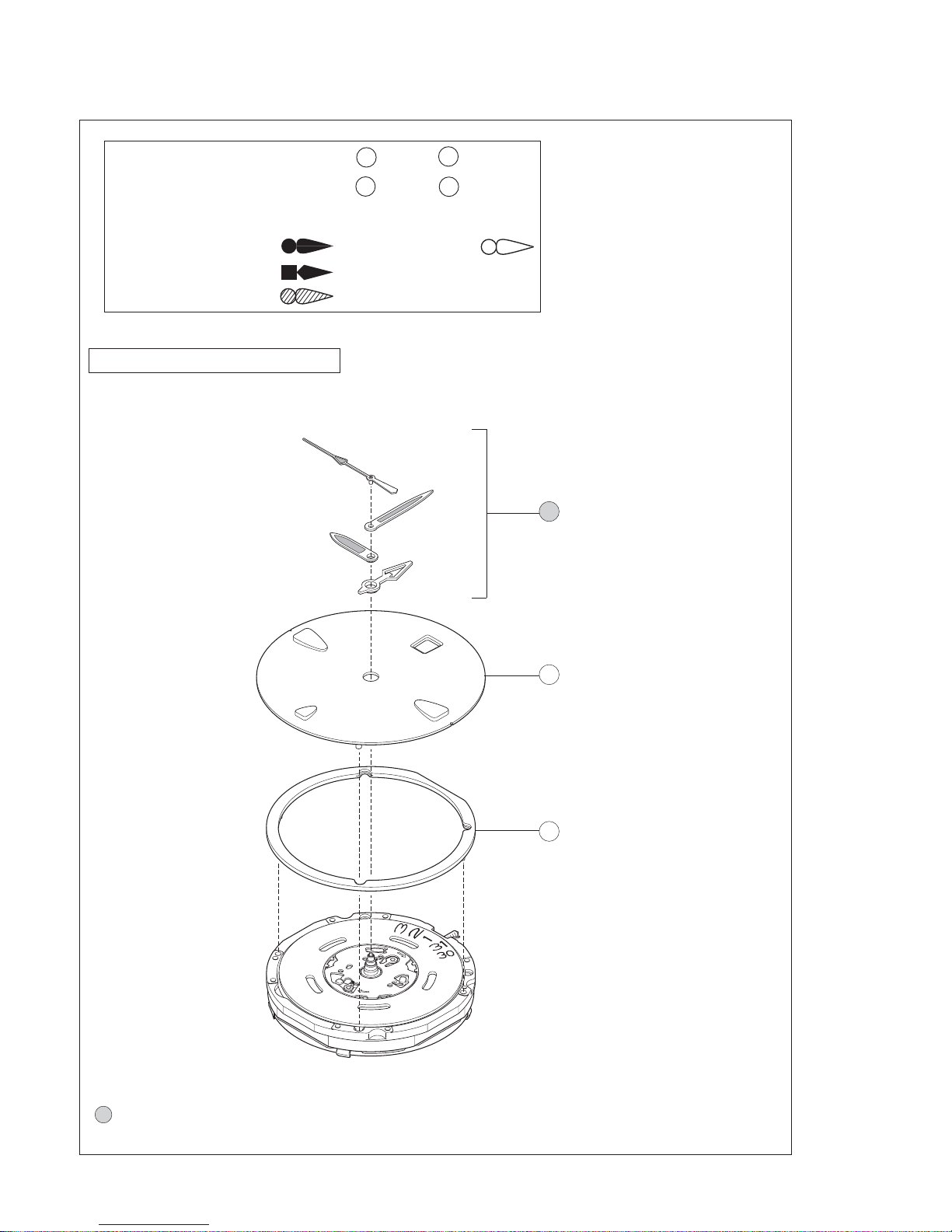
Disassembling procedures Figs.: 1 fi 49
Reassembling procedures Figs.: 49 ‹ 1
Lubricating: Types of oil Oil quantity
Moebius A Normal quantity
Moebius V
Moebius F
Cal. 4F56A, 8F56A & 8F58A
Ex. : Cal. 8F56A
Cal. 4F56A, 8F56A, 8F58A
1 24-hour, Hour, Minute and
second hands
Please see the remarks on the following pages.
2Dial
3 Holding ring for dial
0884 167 (4F56A)
0884 166 (8F56A,8F58A)
2
Page 3

PARTS CATALOGUE
Note Pull out the crown to the first click before starting disassembling or reassembling.
Cal. 4F56A, 8F56A, 8F58A
It is highly recommended that the exclusive
movement holder (S-680) be used for
disassembly or reassembly. Contact SEIKO
SERVICE CENTER to purchase this tool.
4 Battery
For removing or installing the
battery and inputting calendar data,
refer to page 11 to 16.
2 Battery
5 Insulator for battery (A)
A battery with 5 Insulator for
battery (A) (red) may be installed in
some models. Discard this type of
battery after replacing it with a new
battery of the latest model, to which
the insulator for battery (white) is
attached.
Insulator for battery(B) (white)
( + )
( - )
Cal. 4F56A, 8F56A & 8F58A
Ex. : Cal. 8F56A
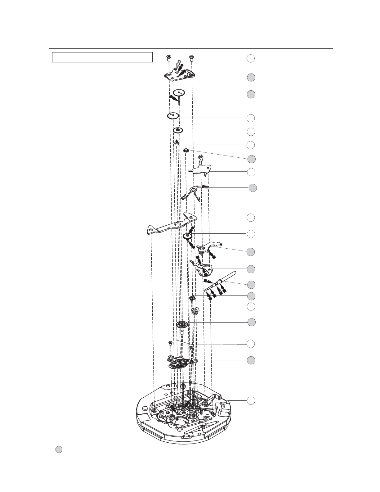
4 Battery
5Insulator for battery (A)
6 Circuit block cover screw
0016 704
7 Circuit block cover
0016 704
• Circuit block cover screw (4 pcs.)
• Train wheel bridge screw (2 pcs.)
0016 705
• Ultrasonic motor screw (2 pcs.)
Please see the remarks on the following pages.
8 Circuit block
4003 424 (4F56A)
4003 091 (8F56A,8F58A)
9 Date driving
contact point spring
4281 115
10 24-hour contact point spring
4281 119
11 Battery connection (–)
4270 415
12 Insulator for battery (B)
4216 116
13 Coil block
4002 115
3
Page 4

PARTS CATALOGUE
Cal. 4F56A, 8F56A & 8F58A
Ex. : Cal. 8F56A
Note Never remove the 24-hour
wheel and date driving wheel
while working on the date dial
replacement(without
disassembling the train wheel
side), as the date driving
contact point spring and 24hour contact point spring may
drop off.
Cal. 4F56A, 8F56A, 8F58A
14 Date dial guard 0808 127
15 24-hour clutch wheel
0273 113
16 Dial Washer
0491 016
17 Date dial
18 Hour wheel
0273 114
19 Intermediate 24-hour driving
wheel and pinion
0817 117
20 Third intermediate wheel for
hour corrector
0168 014
21 Date jumper screw
0012 354
0012 354
Date jumper screw ( 4 pcs. )
Please see the remarks on the following pages.
22 Date jumper
0810 116
23 Calender Plate
0195 014
24 Second intermediate wheel for
hour corrector
0168 013
25 Intermediate date driving wheel
and pinion
0817 118
26 Bush for second intermediate wheel
for hour corrector guide
4247 018
27 Ultrasonic rotor
4062 117
28 24-hour wheel
1019 114
29 Date driving wheel
0802 116
4
Page 5
PARTS CATALOGUE
Cal. 4F56A, 8F56A, 8F58A
Cal. 4F56A, 8F56A & 8F58A
Ex. : Cal. 8F56A
30 Train wheel bridge screw
0016 704
31 Train wheel bridge
0125 254
32 Fourth wheel and pinion
33 Third wheel and pinion
0231 116
34 Fifth wheel and pinion
0701 116
35 Rotor
4146 116
36 Setting wheel
0281 115
37 Yoke guard
0388 116
38 Train wheel setting lever
0391 115
39 Stator
4239 115
40 Minute wheel and pinion
0261 048 (4F56,8F56A)
0261 049 (8F58A)
41 Setting lever
0383 115 (4F56A)
0383 116 (8F56A,8F58A)
42 Yoke
0384 116
Please see the remarks on the following pages.
43 Setting stem
44 Clutch wheel
0282 117
45 First intermediate wheel for hour
corrector
0168 011
46 Center wheel and pinion
47 Ultrasonic stator unit screw
0016 705
48 Ultrasonic stator unit
4234 115
49 Main plate
0100 148 (4F56A)
0100 138 (8F56A,8F58A)
5
Page 6
PARTS CATALOGUE
Cal. 4F56A, 8F56A, 8F58A
Remarks
● Back plate
For some models which use the back plate, refer
to the illustration at the right to mount it.
● Case ring
The type of case ring is determined based on the
case design.
Check the case number and refer to “SEIKO
Casing Parts Catalogue” to choose the appropriate
case ring.
7 Circuit block cover
32 Fourth wheel and pinion
46 Center wheel and pinion
18 Hour wheel
Align the indicator to the
setting stem.
• Discrimination of the hand installation height
Cal. 4F and 8F Series watches have numerals printed on
movement to indicate the hand installation height. When
repairing, refer to the table below.
4F56A
Numeral for
discrimination
2
Circuit
block cover
4461 034
Center wheel and
pinion
0221 122
8F56A
Numeral for
discrimination
2
Circuit
block cover
4461 026
Center wheel and
pinion
0221 122
Numeral for discrimination
Fourth wheel and
pinion
0241 167
Fourth wheel and
pinion
0241 167
Hour wheel
0273 114
Hour wheel
0273 114
6
Page 7
PARTS CATALOGUE
8F58A
Cal. 4F56A, 8F56A, 8F58A
Numeral for
discrimination
2
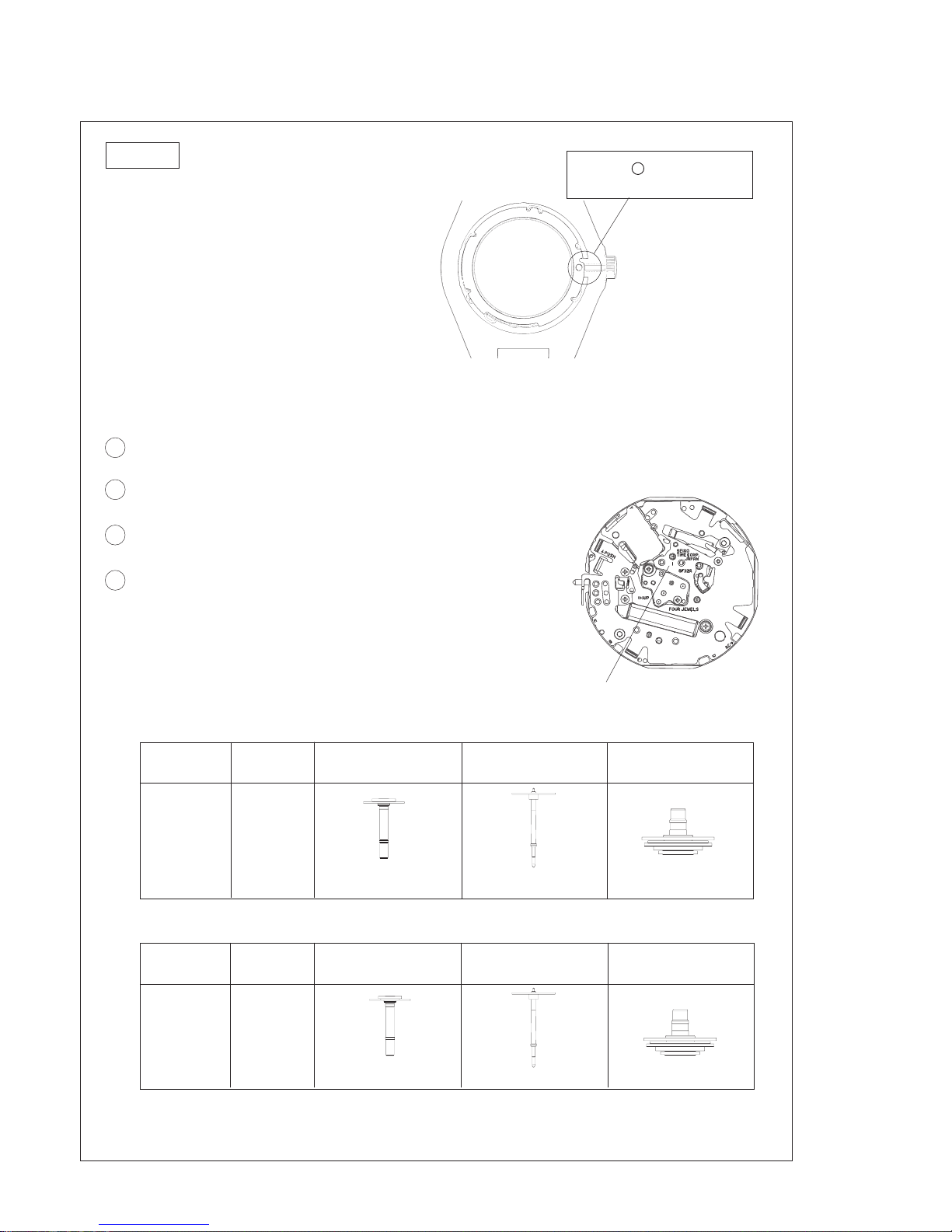
17 Date dial
Cal. No.
4F56A
8F56A
8F58A
The type of date dial is determined based on the case design.
* Not all the types of date dial are shown in the table above.
Check the case number and refer to “SEIKO Casing Parts Catalogue” to choose the appropriate date dial.
Circuit
block cover
4461 035
Part code
0878 320
0878 356
Center wheel and
pinion
0221 124
Position of crown and
calendar frame
3 o'clock
3 o'clock
Fourth wheel and
pinion
0241 167
Color of figure
Black
Black
Hour wheel
0273 114
Color of
background
White
White
43 Setting stem 0351 196
The type of setting stem is determined based on the case design.
Check the case number and refer to “SEIKO Casing Parts Catalogue” to choose the appropriate setting
stem.
7
Page 8

Cal. 4F56A, 8F56A, 8F58A
TECHNICAL GUIDE
• The explanation here is only for the particular points of Cal. 4F56A, 8F56A and 8F58A.
• For repairing, checking or measuring procedures, refer to the “TECHNICAL GUIDE, GENERAL
INSTRUCTIONS”.
I. STRUCTURE OF THE CIRCUIT BLOCK
[ Cal. 4F56A ]
“M” terminal (for month setting)
“ø” terminal
(for resetting the date dial)
[ Cal. 8F56A, 8F58A ]
“ø” terminal
(for resetting
the date dial)
“M” terminal (for month setting)
“Y” terminal (for year setting)
AC terminal
“D” terminal
(for date setting)
“Y” terminal
(for year setting)
Input terminal (+)
C-MOS-IC
Crystal unit
C-MOS-IC
Input terminal (+)
Coil block output terminal
Input terminal (–)
Coil block output terminal
“D” terminal
(for date setting)
AC terminal
8
Crystal unit
Input terminal (–)
Page 9

TECHNICAL GUIDE
II. REMARKS ON DISASSEMBLING AND REASSEMBLING
It is highly recommended that the exclusive movement holder (S-680) be used to disassemble or
reassemble the watch.
Use of other movement holders may make unreliable the screw pins (the gold part) of the main plate.
Be careful not to press the main plate too hard when screwing or unscrewing the pins.
To prevent deformation of the main plate, never use the movement holder which is designed to hold
the movement with only two side guides.
◆ How to use the exclusive movement holder
[ Cal. 4F Series ]
Setting stem guide
Cal. 4F56A, 8F56A, 8F58A
A portion
Disassembling/reassembling procedures :
[ Cal. 8F Series]
A portion
Disassembling/reassembling procedures :
«
1
29
«
29
1
B portion
Disassembling/reassembling procedures :
Setting stem guide
B portion
Disassembling/reassembling procedures :
30
30
«
49
«
49
9
Page 10

TECHNICAL GUIDE
Cal. 4F56A, 8F56A, 8F58A
1 24-hour, hour, minute and second hands
Always set the hands with the battery installed.
Set the movement to the A portion of the exclusive movement holder.
If any other movement holder is used, be certain to place the movement on a secure, flat plate. Pay special
attention not to damage the hooking portion.
Hooking portion
◆ How to set the hands
1. Set 4 Battery. (Refer to page 12.)
2. Set 3 Holding ring for dial.
3. Set 2 Dial.
4. Go to "Necessary procedure after a battery change".
*Refer to page 12 for details.
5. Input the calendar data.
*Refer to page 13 to 16 for details.
Installation of the hands
Turn the crown clockwise until the date changes, then set the hands to point at the 12 o’clock position.
To set the hands more accurately,
1) Turn the crown clockwise until the date changes.
2) Give the crown four counterclockwise turns until the previous date appears.
3) Slowly turn the crown clockwise until the date changes again.
4) Set the hands to point at the 12 o’clock position.
Battery
10
Page 11

TECHNICAL GUIDE
4 Battery
It is highly recommended that the exclusive tool (S-912) be used for removing or
installing the battery, resetting the built-in IC or inputting the calendar data.
Contact SEIKO SERVICE CENTER to purchase this exclusive tool.
S-912
◆ How to remove the battery
1. Insert the tip of the tweezers into the gap between the battery and the circuit block cover at the insertion
point 1 in the illustrations below to gently lift up the battery.
2. Insert the tip of the tweezers into the gap between the battery and the circuit block cover at the insertion
point 2 in the illustrations below to gently lift up the battery.
3. Remove the battery with due care not to damage the coil.
The illustrations below show the new battery installed. (The battery is a new model with the new white
battery insulator.) (In a case where the red insulator is installed, insert the tweezers between the red insulator
and the circuit block cover in the order of the numbers illustrated below.) Take care not to insert the tweezers
too deep into the gap as this may damage the coil.
Cal. 4F56A, 8F56A, 8F58A
[ Cal. 4F56A ]
Insertion point 2
Insertion point 1
[ Cal. 8F56A, 8F58A ]
Insertion point 1
Insertion point 2
11
Page 12

TECHNICAL GUIDE
Cal. 4F56A, 8F56A, 8F58A
◆ How to install the battery
1. In a case where a red battery insulator is installed, remove and discard it.
2. To install a new battery with a battery insulator, align the tip of the arrow mark on the seal attached
to the battery with the crown. Then press it towards the portion for a battery check. Be careful not to deform
the portion for battery check.
*Make sure that the battery is securely fixed by the four hooking portions.
3. After the battery is installed, turn to the "Necessary procedure after a battery change".
4. After completing the "Necessary procedure after a battery change", turn to “How to input the calendar
data.”
Grounding portion
Portion for battery check
◆ Necessary procedure after a battery change
1. After the battery is replaced with a new one, push the crown back to its normal position.
2. Contact the “AC” terminal of the circuit block and the (+) surface of the battery with a S-912 tool or
conductive tweezers for more than three seconds to reactivate the built-in IC.
➔
Be careful not to damage the circuit block. (To prevent any damage to the circuit block, it is highly
recommended the exclusive tool S-912 be used .)
Battery
AC Terminal
Reactivate the built-in IC by contacting the AC
terminal and the side face of the battery with the
tip of the tool.
2
[ Position of AC terminal of
Cal. 8F (Gent's) Series ]
B
1
R
4
2
AC Terminal
[ Position of AC terminal of
Cal. 4F (Ladies') Series ]
Circuit Block
AC Terminal
12
Page 13

TECHNICAL GUIDE
◆How to input the calendar data
A How to check the calendar data (after battery change)
■
1. Pull out the crown to the first (or the second) click, then
immediately push it back to its original position.
Gently support the battery with fingers and securely hold
the movement.
➟
2
2. Check the movement of the second hand and follow the flowchart below.
Five-second interval movement
➟
One-second interval movement :
The data is retained securely.
Go to C. How to check the calendar data.
Cal. 4F56A, 8F56A, 8F58A
Five-second interval movement :
The data has been erased.
Go to B. How to input the calendar data.
One-second
interval
movement
Five-second
interval
movement
If the second hand shows neither one-second interval movement nor five-second interval movement,
return to the "Necessary procedure after a battery change" followed by A. How to check the calendar data
(after battery change).
C.
How to check
the Calendar
Data
The data is correct.
Complete.
The data is wrong.
B.
How to input
the calendar
data
13
Page 14

TECHNICAL GUIDE
B How to input the calendar data
■
To input the calendar data, activate the circuit by
contacting each terminal and the side face of the battery
repeatedly with tweezers. Be careful not to damage the
circuit block.
Cal. 4F56A, 8F56A, 8F58A
Battery
Circuit Block
Year
Month
Ø
[ Position of the terminals of Cal. 8F (Gent's) Series ]
• Input each calendar data item in the following order.
2
B
1
R
4
2
AC
Date
Ø Y M D
Resetting
the date dial position
Set the date dial to “1”.
Year setting
Set the date dial to
the current year.
Year
Month
Ø
[ Position of the terminals of Cal. 4F (Ladies') Series ]
Month setting
Set the date dial to
the current month.
AC
C
R
1
6
1
2
Date setting
Set the date dial to
the current date.
Date
1. Pull out the crown to the second click.
[8F]
1
Ø
[4F]
Ø
2. Contact the “Ø “ terminal with the tip of tweezers until “1” appears
14
in the calendar frame.
Page 15

TECHNICAL GUIDE
Cal. 4F56A, 8F56A, 8F58A
2
[Ex. : July]
7
[Ex. : 12th.]
12
[8F]
[4F]
[8F]
[4F]
[8F]
[4F]
3. Contact the “Y” terminal with the tip of tweezers until the year
Y
Y
number representing the current year appears in the calendar frame.
(Refer to the table below for the year number.)
4. Contact the “M” terminal with the tip of tweezers until the current
month appears in the calendar frame.
M
M
5. Contact the “D” terminal with the tip of tweezers until the current
date appears in the calendar frame.
D
D
[8F]
6. Contact the “Ø “ terminal with the tip of tweezers once to check if “1”
appears in the calendar frame.
If “1” does not appear in the calendar frame, redo the whole
1
Ø
[4F]
Ø
procedures from 1 to 6 once again.
7. Push the crown back to its original position.
For the year number which represent the current year in the calendar frame, refer to the table below.
Year number in the calendar frame
1 234
One year since
the last leap year
Year
2001
2005
2009
•
•
Two years since
the last leap year
2002
2006
2010
•
•
Three years since
the last leap year
2003
2007
2011
•
•
Leap year
2004
2008
2012
•
•
15
Page 16

Cal. 4F56A, 8F56A, 8F58A
TECHNICAL GUIDE
C How to check the calendar data (After inputting the data)
■
Ex.: July 12, 2002
Pull out the crown to the first click, then immediately push it back to its original position. Gently support the
battery with fingers to securely hold the movement.
Each calendar data item will be shown in the following order.
Year
Month
Date
Ex.: July
Ex.: 12th.
The number of times that the second hand moves in five-second
intervals indicates the number of the year which has passed since
the last leap year.
Ex. Year 2002:
The year number 2 ; the second hand moves twice in five-second
intervals.
The current month will be displayed for a while in the calendar
frame.
7
Subsequently the current date will be displayed in the calendar
frame.
12
If all the data items are correct, proceed to the time setting.
When setting the time, make sure that AM/PM is properly set.
Note
This watch does not feature an Automatic Calendar Function.
Date is interlocked to the movement of the hands.
Be certain that AM/PM is properly set when setting the time to prevent the wrong date from appearing.
If any data item is not correct, return to B. How to input the calendar data and repeat the whole procedures
once again.
16
Page 17

TECHNICAL GUIDE
Note Pull out the crown to the first click before starting disassembling or reassembling.
7 Circuit block cover
Reassembling :
When setting the circuit block cover, take care not to deform the terminal for battery check.
[ Cal. 4F56A ] [ Cal. 8F56A, 8F58A ]
Cal. 4F56A, 8F56A, 8F58A
Terminal for battery check
8 Circuit block
Disassembling :
Insert tweezers from the positions indicated in the illustration below to remove the circuit block.
Reassembling :
Locate the circuit block using the guide pin A on the coil side. Then gently press down the guide pin B
under the 24-hour wheel to fix the circuit block.
When mounting the circuit block, make sure that the date driving contact point spring and 24-hour contact
point spring are correctly mounted and that the tip of the reset lever is positioned at the center of the
eyehole as shown in the illustration below.
Positions to insert tweezers
Guide pin A
Terminal for battery check
Tip of the reset lever terminal
(Center of the eyehole)
Guide pin B
Eyehole
17
Page 18

TECHNICAL GUIDE
Cal. 4F56A, 8F56A, 8F58A
9 Date driving contact point spring
10 24-hour contact point spring
• Setting position
Date driving contact point spring 24-hour contact point spring
Note The date driving contact spring and the 24-hour contact point spring contact with the circuit block to
drive and control the ultrasonic motor. Failure of this electric contact will cause a malfunction of the
ultrasonic motor or defective calendar display. To guard against this problem, carefully handle the
contact point springs not to bend or straighten them.
To prevent a problem caused by deformation of the springs, it is recommended that the springs be
replaced with new ones at the time of disassembling or reassembling.
14 Date dial guard
Unlike conventional movements, the date dial guard is not fixed
with screws. It is set to the main plate with the three protrusions,
which are caught under the main plate by turning the guard.
Then, it is fixed by the two guide pins.
• How to remove
1. Gently lift up the A portion of the date dial guard with
tweezers to clear it from the guide pin, and then, move it in
the clockwise direction until it gets on the guide pin.
2. Release the B portion of the date dial guard in the same
manner as you release the A portion, and then, move it in
the clockwise direction until it gets on the guide pin.
3. Check that all the three protrusions of the date dial guard
have come off the main plate. Then, remove the date dial
guard.
Note Take care not to deform the date dial guard, as it is
softly built.
D portion
B portion
A portion
Guide pin
Date dial guard
C portion
18
Date dial guard
E portion
Date dial guard
Guide pin
Page 19

TECHNICAL GUIDE
Cal. 4F56A, 8F56A, 8F58A
• How to install
1. Put the date dial guard on the main plate so that the
A and B portions are over the guide pins, as shown
in the illustrations at the right.
2. Move protrusion D of the date dial guard in the
counterclockwise direction so that it is caught under
the main plate.
3. Slightly move protrusions C and E in the
counterclockwise direction alternately to set them
under the main plate. While doing so, set the A and
B portions of the date dial guard to the guide pins.
Note Take care not to press down the ultrasonic rotor
pinion while installing the date dial guard.
Ultrasonic rotor pinion
Protrusion D
B portion
Protrusion C
A portion
Protrusion E
18 Hour wheel
Refer to the illustration below for lubricating.
Lubricating hole
Caution must be taken not to
spill oil over the wheel.
Caution must be taken not to
spill oil inside.
19
Page 20

TECHNICAL GUIDE
25 Intermediate date driving wheel and pinion
27 Ultrasonic rotor
Cal. 4F56A, 8F56A, 8F58A
28 24-hour wheel
29 Date driving wheel
• Setting position
Refer to the illustration at the right.
Intermediate date driving
24-hour wheel
Ultrasonic rotor
wheel and pinion
Date driving wheel
Note The pinions of the ultrasonic rotor and date driving wheel are made of plastic. Be careful not
to damage or deform them while working on reassembling or disassembling.
27 Ultrasonic rotor 48 Ultrasonic stator unit
Note When holding the ultrasonic rotor and ultrasonic stator unit with tweezers, be sure to catch the
portions illustrated below. Failure to do so may adversely affect their functions.
Ultrasonic rotor
Ultrasonic stator unit
Do not touch here.
Tweezers
Tweezers
Keep this side away from dust or dirt.
20
Page 21

TECHNICAL GUIDE
Cal. 4F56A, 8F56A, 8F58A
31 Train wheel bridge
• Setting position of the wheels
36 Setting wheel
Make sure that the top face is up.
Train wheel bridge side
Main plate side
38 Train wheel setting lever
41 Setting lever
Step rotor
Fifth wheel and pinion
Setting wheel
Minute wheel and pinion
Fourth wheel and pinion
Third wheel and pinion
42 Yoke
• Setting position
Train wheel
setting lever
Setting lever
Yoke
Make sure that the spring of the yoke is
appropriately fit into the frame of the
main plate.
Note Handle with care not to deform the spring of the york.
When the circuit block cover is missing, do not pull out or push back the
crown.
44 Clutch wheel
To mount the clutch wheel, set the smaller face width of the wheel toward the center of the
setting wheel.
Setting wheel
Clutch wheel
setting stem
Yoke
21
Page 22

TECHNICAL GUIDE
Cal. 4F56A, 8F56A, 8F58A
III. VALUE CHECKING
● Coil block resistance
3.6 KW ~ 4.0 KW
Measuring the coil block resistance
1. Measure the resistance with the coil block installed on the main plate.
2. Apply the red and black probes of the tester to the patterns of the coil lead terminal. While doing so,
take care not to touch the end portion of the coil lead terminal, as this will break the coil wire.
Coil board pattern
● Current consumption
For the whole movement : Less than 1.3 mA (with voltage of 3.0 V supplied from a battery)
For the circuit block alone : Less than 0.9 mA (with voltage of 3.0 V supplied from a battery)
Measuring the current consumption for the whole movement
1. Check that the crown is in the normal (pushed in) position.
Black probe
Red probe
2. Apply the red and black probes of the tester to the circuit block cover and the pattern of the (–) terminal
of the circuit block, respectively.
3. After connecting the tester, contact the “AC” terminal of the circuit block and the circuit block cover
with conductive tweezers. Then, after approximately 20 seconds, start measurement, checking that
a stable measurement is obtained.
Measuring the current consumption for the circuit block alone
1. Connect the tester to the input terminals (+) and (–), and contact the “AC” and (+) terminals with
conductive tweezers. Then, after approximately 10 seconds, start the measurement, checking that
a stable measurement is obtained.
* While measuring current consumption, be sure to protect the circuit block from light with black
cloth or the like, as the light may increase the current consumption, resulting in an inaccurate
measurement.
Note When the current consumption for the whole movement exceeds the standard value while the
current consumption for the circuit block alone is within the standard value range, a driving pulse
may be generated to compensate for the heavy load applied on the gear train, etc. In that case,
overhaul and clean the movement parts, and then, measure the current consumption for the
whole movement again.
22
Page 23

4F56A, 8F56A, 8F58A
Page 24

【Supplement】 Time accuracy adjustment by crown operation
(Only recommended to the Service Centers of SEIKO Affiliates and Distributors)
Although time accuracy is normally adjusted by pattern cutting (P.21), in case it cannot be adjusted within the
standard accuracy by this method, please adjust by the crown operation which is shown below:
2) Push back the
crown to the first click
from the second click.
The second hand
starts to move at the
same time.
3) Leave this 2) condition for 5 seconds and then
pull the crown out to the second click again.
(note: The second hand starts to move by the
operation 2), after 5 seconds by the second
hand, then pull the crown out to the second
click.)
1) Pull out the
crown to the
second click.
After you push back the crown to the original position (0 click), the calendar returns to the current date
and the second hand starts to move. (During the time when you are adjusting the accuracy, the watch
has been stopped and the time setting is necessary after the adjustment has finished.)
4) According to the above operations, the calendar
automatically moves as follows:
① The calendar will move to 8 from the current
date and stops initially.
② Then it automatically moves from 8 to 1 in order.
③ Then it automatically moves from 1 to 15 in order, each date takes 3 seconds to change to the next date.
The dates 1 to 15 correspond to the adjustable seconds in the following table.
Therefore, you have to decide beforehand how many seconds are necessary to adjust.
.
after 5 seconds
Note: Regarding the adjustable
seconds, this is based on
accuracy before adjustment.
The adjustable amount is upto
–0.056, and you cannot increase
it beyond the limit by repeating
the above operations.
④ You choose the date according to the adjustable seconds and push the
crown to the original (0 click) position while the target date is displayed.
eg.) present accuracy: 0.100 seconds/day
When adjusted to be –0.056 seconds/day
Push the crown at the moment when the calendar shows “15”. The accuracy after
the adjustment is about 0.044 seconds/day. If you have not pushed back the crown
at the date which should be done, the calendar changes to 16 after 15 and returns to
the current date.
3 seconds
3 seconds 3 seconds 3 seconds
*
*
21
(supplement)
Cal. 4F56A, 8F56A, 8F58A
Page 25

Tips on repairing the perpetual calendar (4F,8F Series)
• Be aware that incorrectly-input calendar data will cause a wrong calendar display.
• For troubleshooting problems with the calendar, refer to the table below.
Symptoms
• The calendar does
not work.
• The second hand
moves at a fivesecond interval.
Problems
• The battery is running low.
• The insulator for the battery is out of
alignment and the battery has
shorted.
• The battery is not securely set to the
battery holder of the circuit block
cover.
• Problems with parts of the date dial
or the date dial guard, or the date dial
or the date dial guard is incorrectly
mounted.
• The date driving contact point spring
or 24-hour contact point spring is not
contacted with the circuit block.
• The calendar data is incorrectly input.
• The calendar data is incorrectly input.
• The insulator for battery is out of
alignment and the battery is shorted
out.
Solutions
• Replace the battery.
• Set correctly the insulator for the battery.
• Use a new battery with the battery insulator.
• Securely set the battery to the battery
holder of the circuit block cover.
• Check the parts of the date dial or the date
dial guard and replace them with new ones
as necessary or remount them correctly.
• Remove all dust or dirt on contact points of
the date driving contact point spring, 24hour contact point spring or the circuit
block.
• Replace the date driving contact point spring
or 24-hour contact point spring with new
ones.
• Refer to the technical guide to correctly
input the calendar data.
• Refer to the technical guide to correctly
input the calendar data.
• Set correctly the insulator for battery.
• Use a new battery with battery insulator.
Reference
p.11,12
p.3
p.11,12
p.18,19
p.18
p.13-16
p.13-16
p.3
• The calendar
display is wrong.
•A character(s) of
the calendar is out
of the calendar
frame.
• The calendar data is incorrectly input.
• The date driving contact point spring,
24-hour contact point spring or the
circuit block are dirty.
• The date dial or the date dial guard is
incorrectly mounted.
• The date dial or the date dial guard is
deformed or deteriorated.
• The train wheel setting lever is out of
alignment.
• The portion for battery check of the
circuit block cover is deformed.
• Problems with parts of the date dial
or the date dial guard, or the date dial
or the date dial guard is incorrectly
mounted.
• Refer to the technical guide to correctly
input the calendar data.
• Remove all dust or dirt on the contact points
of the date driving contact point spring, 24hour contact point spring or the circuit block.
• Refer to the technical guide to correctly
remount them.
• Replace the date driving contact point spring
or 24-hour contact point spring with new
ones.
• Check if the train wheel setting lever
operates normally or remount it as
necessary. Note that it must be mounted
with the crown at the first click position.
• Reshape the deformed part. Replace the
circuit block cover with a new one as
necessary.
• Check the parts of the date dial or the date
dial guard and replace them with new ones
as necessary or remount them correctly.
* For troubleshooting of the general defects of conventional quarts watches, refer to the “TECHNICAL
GUIDE, GENERAL INSTRUCTIONS”.
p.13-16
p.18
p.18
p.18
p.21
p.17
p.18,19
23
Page 26

24
2004-02-01
 Loading...