

Seiko 4F32A, 8F33A, 8F35A, 8F32A Technical Manual
1
PARTS CATALOGUE / TECHNICAL GUIDE
[SPECIFICATIONS]
Cal. No.
Item
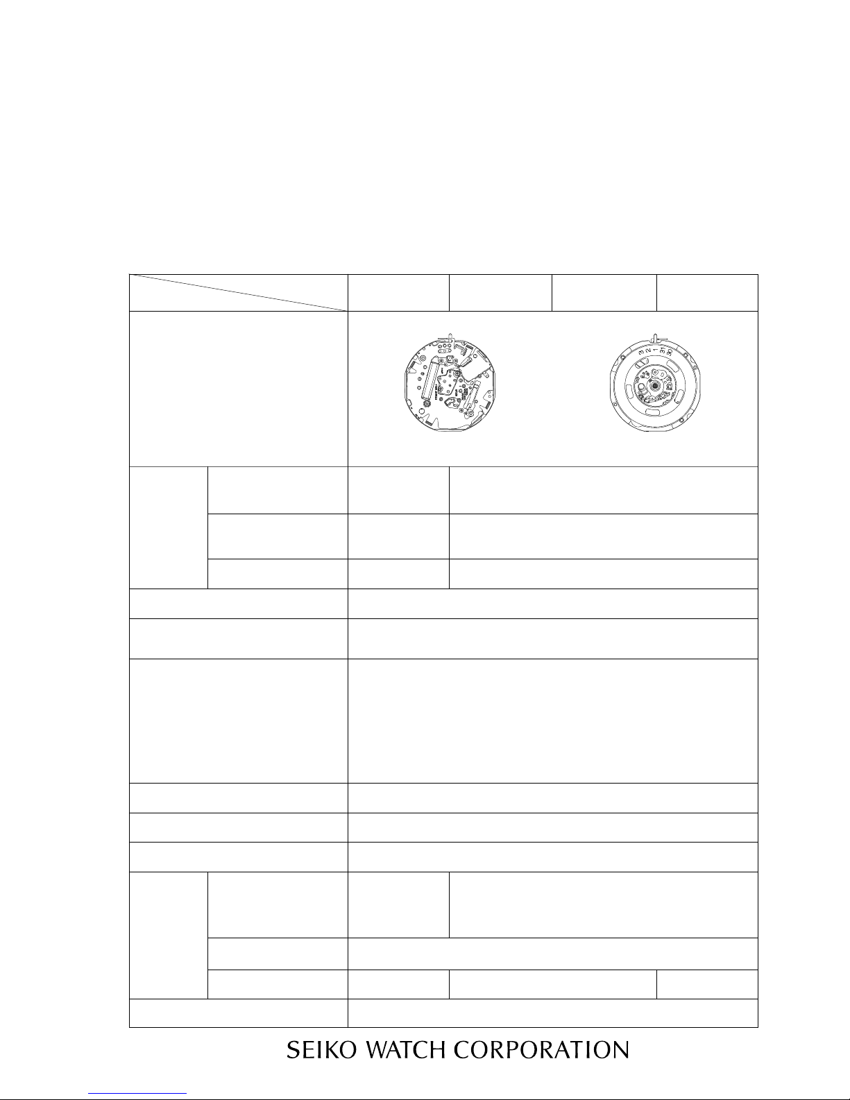
4F32A 8F35A
Movement
8F32A
8F33A
(x 1.0)The illustrations refer to Cal. 8F32A.
Movement
size
ø18.5 mm
17.7 mm x
18.5 mm
ø26.4 mm
25.6 mm x 25.6 mm
ø18.5 mm
17.1 mm x
18.5 mm
ø26.4 mm
24.8 mm x 24.8 mm
Time indication 3 hands (hour, minute and second hands)
Outside diameter
Casing diameter
Height
)
Including the
battery portion
(
3.9 mm 4.3 mm
Driving system
Additional mechanism
Loss/gain Annual rate at normal temperature range: less than 20 seconds
Regulation system
Logical regulation (Pattern cutting system: 3 steps)
Measuring gate by quartz tester Use 10-second gate.
SEIKO CR1612
Battery
Battery No
SEIKOBR2412
Voltage 3.0 V
Battery life Approx. 5 years
Approx. 8 yearsApprox. 10 years
Jewels 4 jewels
Cal. 4F32A, 8F32A
Cal. 8F33A, 8F35A
PARTS CA TALOGUE / TECHNICAL GUIDE (p. 1 – 22)
CATÁLOGO DE PARTES / GUÍA TÉCNICA (p. 23 – 44)
• Step motor (for hour, minute and second hands)
• Ultrasonic motor (for calendar indication)
• Calendar (Leap year indication, month and date)
Perpetual calendar up to February 28, 2100
• Train wheel setting device
• Electronic circuit reset switch
• Battery life indicator
• Day calendar (Cal. 8F33A)
• Instant calendar (day) setting device (Cal. 8F33A)
(Revised: 2008 Apr.)
.
Revision: 2008.4

2
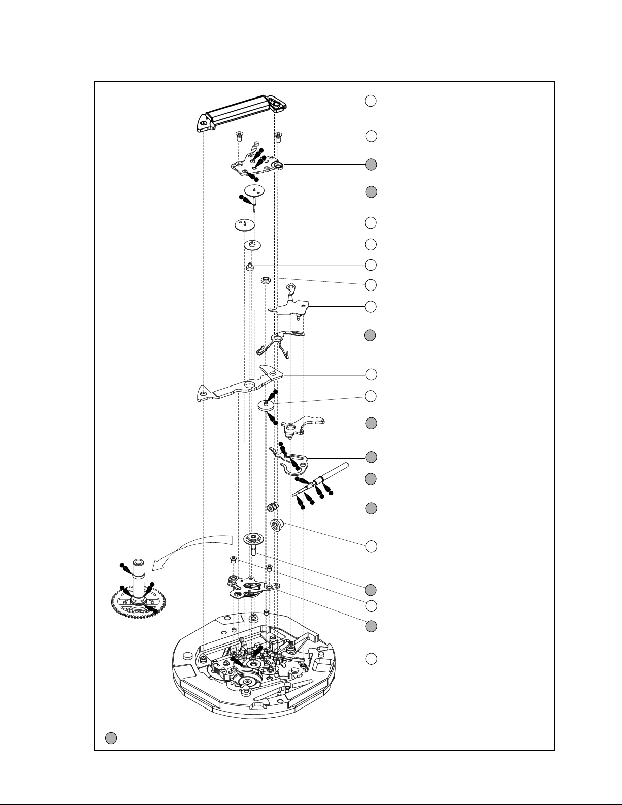
PARTS CATALOGUE
Disassembling procedures Figs. : 1 → 43
Reassembling procedures Figs. : 43 ← 1
Lubricating: Types of oil Oil quantity
Moebius A No
rmal quantity
Moebius F
➡➡
Please see the remarks on the following pages.
Cal. 4F32A, 8F32A, 8F33A, 8F35A
Ex. : Cal. 8F32A
Note for Cal. 8F32A and 8F35A:
When the hands and the dial
are removed, the dial spacer
wi
ll come off if the movement
is turned over. Take care not
to
lose the dial spacer.
0016 704
• Circuit block cover screw (4 pcs.)
•
Train wheel bridge screw (2 pcs.)
00
16 705
•
Ultrasonic motor screw (2 pcs.)
2 Battery
(See the front page)
5 4216 115 (Cal. 4F32A)
4216 117 (Cal. 8F32A,
8F33A and 8F35A)
In
sulator for battery (A)
6 0016 704
Ci
rcuit block cover screw
7
Circuit block cover
8 4003 424 (Cal. 4F32A)
4003 425 (Cal. 8F32A,
8F33A and 8F35A)
Circuit block
10 4281 119
24-hour contact point
spring
11 4270 415
Battery connection (–)
12 4216 116
Insulator for battery (B)
9 4281 115
Date driving contact
po
int spring
*For disassembling and reassembling,
use the movement holder for exclusive
use with the respective calibres.
*For the dial side:
•
Movement holder 4F3-T
for Cal. 4F32A
•
Movement holder 8F3-T
for Cal. 8F32A, 8F33A and 8F35A
*For the case back side:
•Movement holder 4F8F-C
for all Cal. 4F and 8F Series
( + )
( - )
Insulator for battery(B) (white)
2 Battery
5 Insulator for battery (A)
A battery with 5 Insulator for
battery (A) (red) may be installed in
some models. Discard this type of
battery after replacing it with a new
battery of the latest model, to which
the insulator for battery (white) is
attached.
3
PARTS CATALOGUE
➡➡
Please see the remarks on the following pages.
Cal. 4F32A, 8F32A, 8F33A, 8F35A
Ex. : Cal. 8F32A
23 4239 115
Rotor stator
24 0261 115 (Cal. 4F32A, 8F32A and 8F33A)
0261 046 (Cal. 8F35A)
Minute wheel and pinion
25 0383 115 (Cal. 4F32A)
0383 116 (Cal. 8F32A, 8F33A and 8F35A)
Setting lever
26 0384 115
Yoke
27 Winding stem
28 0282 032 (Cal. 4F32A and 8F32A)
0282 117 (Cal. 8F33A)
0282 116 (Cal. 8F35A)
Clutch wheel
290962 119 (Cal. 8F33A)
First intermediate wheel for calendar corrector
30 Center wheel and pinion
41 0016 705
Ultrasonic stator unit screw
42 4234 115
Ultrasonic stator unit
43 0100 136 (Cal. 4F32A)
0100 137 (Cal. 8F32A, 8F33A and 8F35A)
Main plate
13 4002 115
Coil block
14 0016 704
Train wheel bridge screw
15 0125 254
Train wheel bridge
16 Fourth wheel and pinion
17 0231 116
Third wheel and pinion
18 0701 115
Fifth wheel and pinion
19 4146 116
Step rotor
20 0281 115
Setting wheel
21 0388 117 (Cal. 4F32A)
0388 116 (Cal. 8F32A, 8F33A and 8F35A)
Yoke guard
22 0391 115
Train wheel setting lever
0282 117•(Cal. 4F32A, 8F32A,
8F33A, 8F35A)
(update: 2007/04/16)
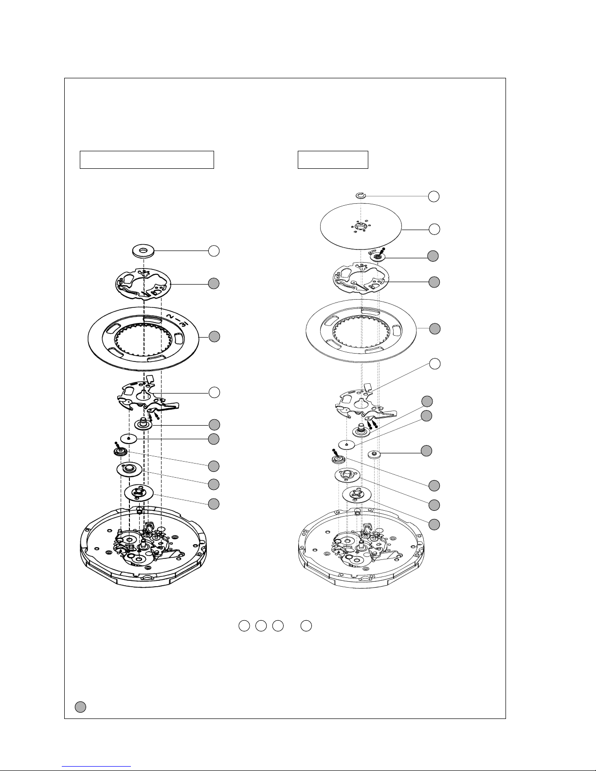
4
PARTS CATALOGUE
➡➡
Please see the remarks on the following pages.
Cal. 4F32A, 8F32A, 8F33A, 8F35A
Cal. 4F32A, 8F32A & 8F35A
Ex. : Cal. 8F32A
Cal. 8F33A
* Cal. 4F32A, 8F32A and 8F35A do not use the parts 3 , 4 , 31 and 37 .
1 4408 116
(Cal. 8F32A and 8F35A)
Dial spacer
32 0808 126
Date dial guard
33 Date dial
34 0810 115
Date jumper
35 Hour wheel
36 0817 118
Intermediate date driving
wheel and pinion
38 4062 117
Ultrasonic rotor
39 1019 114
24-hour wheel
40 0802 115
Date driving wheel
3 0963 230
Snap for day star
with dial disk
4 Day star with
dial disk
32 0808 125
Date dial guard
33 Date dial
31 0989 007
Day corrector
wheel
38 4062 117
Ultrasonic rotor
39 1019 115
24-hour wheel
40 0802 115
Date driving
wheel
36 0817 118
Intermediate date
driving wheel and
pinion
37 0962 118
Second intermediate
wheel for calendar
corrector
35 Hour wheel
34 0810 115
Date jumper
5
PARTS CATALOGUE
Cal. 4F32A, 8F32A, 8F33A, 8F35A
Remarks:
● Back plate
Some models do not use the back plate.
● Case ring
The type of case ring is determined based on the design of cases.
Check the case number and refer to “SEIKO Casing Parts Catalogue” to choose a corresponding case ring.
4 Day star with dial disk (Only for Cal. 8F33A)
Position of crown
and calendar frame
Cal. No. Color of figurePart code
Color of
background
8F33A 0170 072 3 o’clock Black White
The type of day star with dial disk is determined based on the design of cases.
Check the part code printed on the disk.
7 Circuit block cover
16 Fourth wheel and pinion
30 Center wheel and pinion
35 Hour wheel
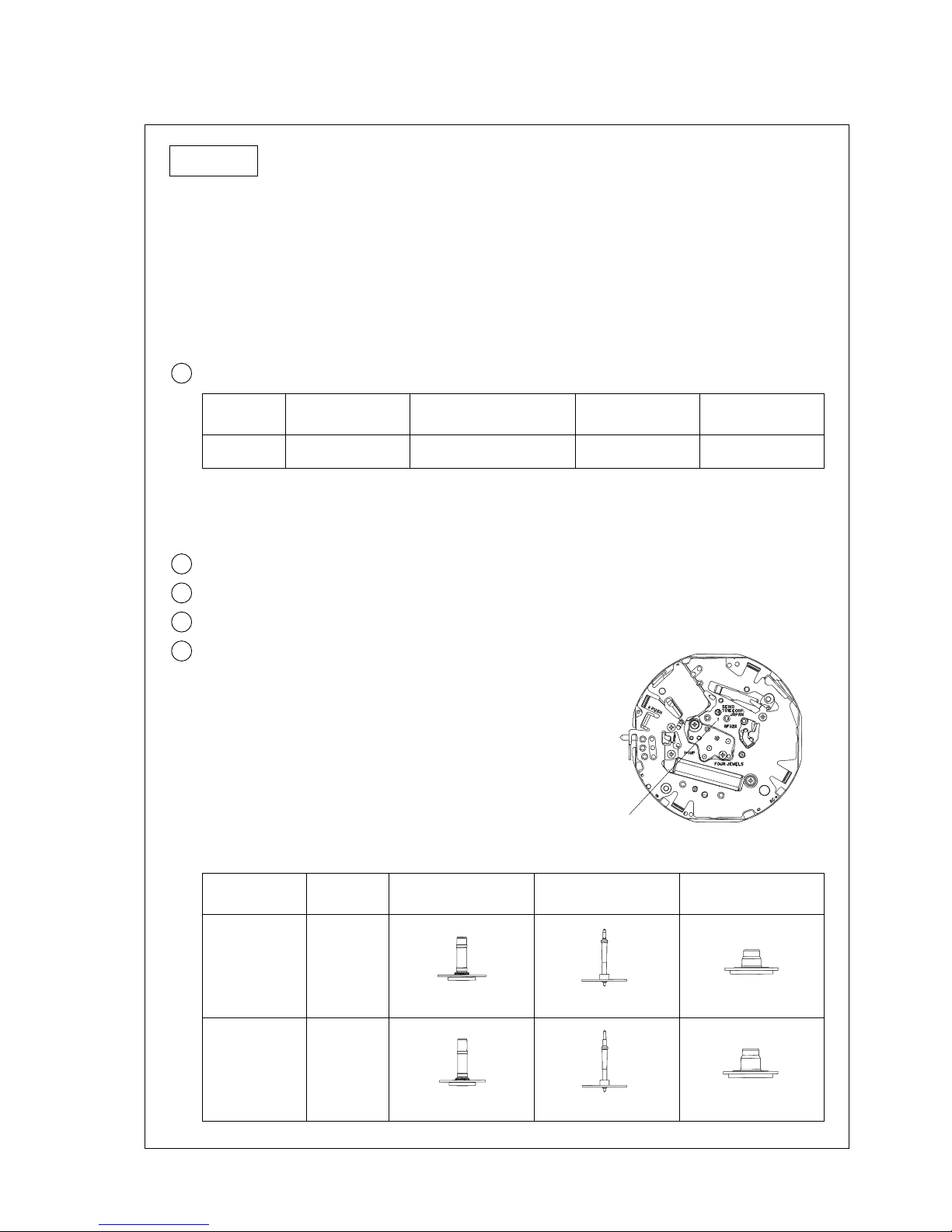
• Discrimination of the hand installation height
Cal. 4F and 8F Series watches have numerals printed on
movement to indicate the hand installation height. When
repairing, refer to the table below.
Circuit
block cover
Numeral for
discrimination
Center wheel
and pinion
Fourth wheel
and pinion
Hour wheel
1
4461 021 0221 116 0241 449 0273 118
2
4461 020 0221 114 0241 448 0273 117
[ Cal. 4F32A ]
Numeral for discrimination
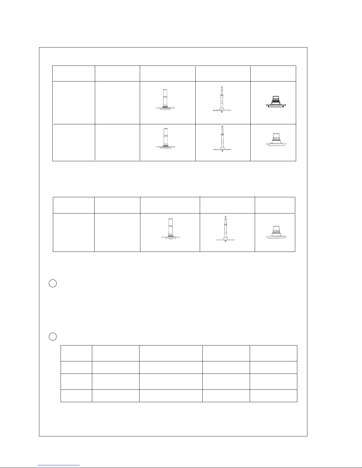
6
PARTS CATALOGUE
Cal. 4F32A, 8F32A, 8F33A, 8F35A
[ Cal. 8F32A and 8F33A ]
Numeral for
discrimination
Center wheel
and pinion
Fourth wheel
and pinion
Hour wheel
[ Cal. 8F35A ]
Numeral for
discrimination
2
Center wheel
and pinion
Fourth wheel
and pinion
Hour wheel
0221 123
27 Winding stem 0351 196
The type of winding stem is determined based on the design of cases.
Check the case number and refer to “SEIKO Casing Parts Catalogue” to choose a corresponding
winding
stem.
33 Date dial
Position of crown
and calendar frame
Cal. No. Color of figurePart code
Color of
background
4F32A 0878 321 3 o’clock Black White
8F35A 0878 301 4 o’clock White Black
8F32A
8F33A
0878 301 3 o’clock White Black
The type of date dial is determined based on the design of cases.
Check the case number and refer to “SEIKO Casing Parts Catalogue” to choose a corresponding date
dial.
Circuit
block cover
2
0221 115
4461 022
(8F32A)
4461 024
(8F33A)
0221 114
1
4461 023
(8F32A)
4461 025
(8F33A)
Circuit
block cover
4461 033
0241 446 0273 115
0241 448
0273 116
0241 446
0273 115
(Addition: hand installation height 1, Column of Circuit block cover) 2008.04
(Addition: Column of Circuit block cover) 2008.04
7
TECHNICAL GUIDE
• The explanation here is only for the particular points of Cal. 4F32A, 8F32A, 8F33A and 8F35A.
• For the repairing, checking and measuring procedures, refer to the “TECHNICAL GUIDE, GENERAL
INSTRUCTIONS”.
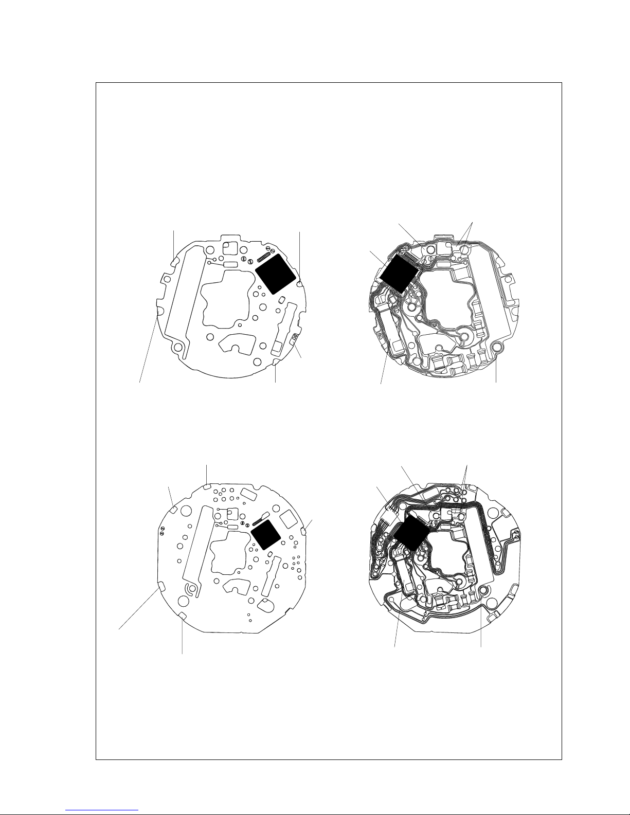
I. STRUCTURE OF THE CIRCUIT BLOCK
Cal. 4F32A, 8F32A, 8F33A, 8F35A
[ Cal. 4F32A ]
[ Cal. 8F32A, 8F33A and 8F35A ]
“ø” terminal
(for resetting the date dial)
“M” terminal
(for month setting)
“Y” terminal
(for year setting)
“D” terminal
(for date setting)
AC terminal
Coil block output terminal
Input terminal (+)
C-MOS-IC
Input terminal (–)Crystal unit
“ø” terminal
(for resetting
the date dial)
“M” terminal (for month setting)
“D” terminal
(for date setting)
AC terminal
“Y” terminal
(for year setting)
Coil block output terminalInput terminal (+)
C-MOS-IC
Input terminal (–)Crystal unit
8
TECHNICAL GUIDE
II. REMARKS ON DISASSEMBLING AND REASSEMBLING
Cal. 4F32A, 8F32A, 8F33A, 8F35A
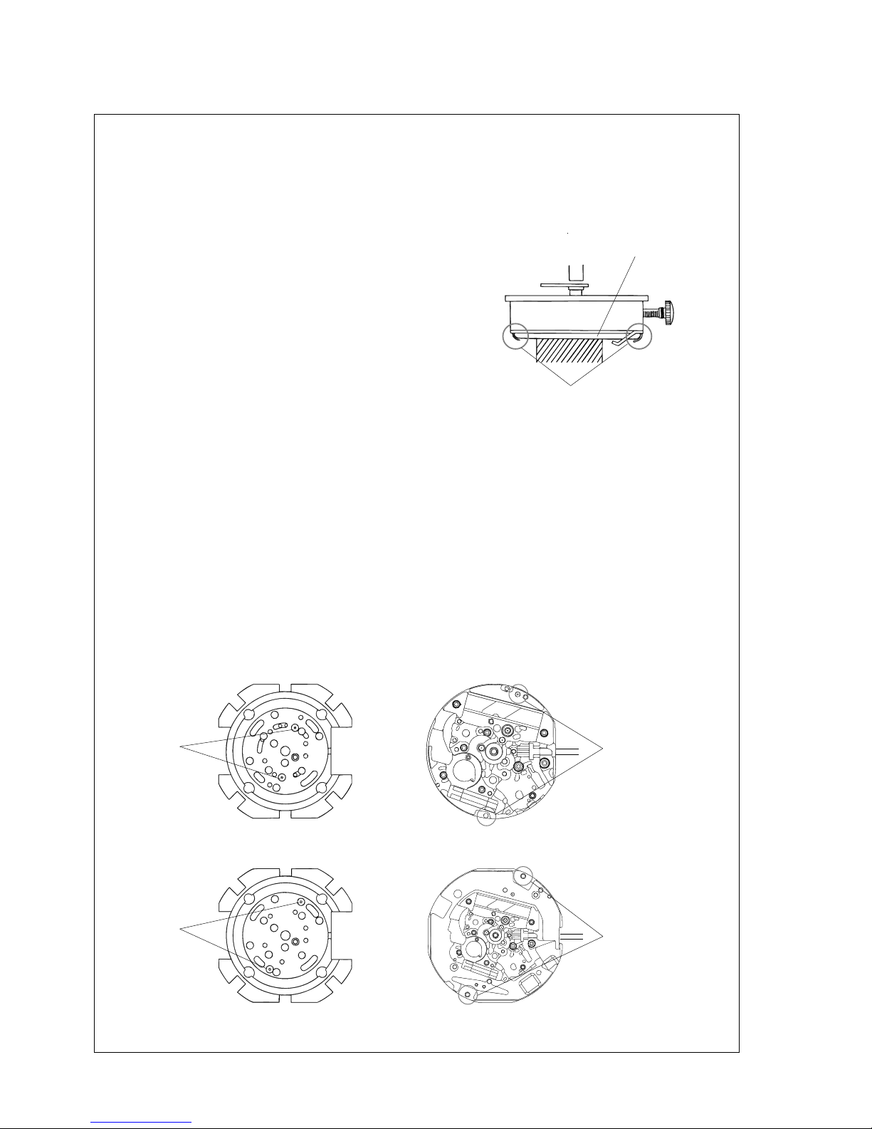
● Hour, minute and second hands
• For disassembling and reassembling, use the movement holder for exclusive use with the respective
calibres.
• When installing the hands, place the movement directly on a flat metal plate or a riveting plate.
• How to set the hands
With the battery installed, place the movement directly
on a flat metal plate or a riveting plate, taking care not
to press down the hooking portions.
To install the hands:
Turn the crown clockwise until the date changes, and install the hands so that they point to the 12 o’clock
position.
To install the hands so that the date changes more accurately as the hands indicate 12 o’clock midnight:
1) Turn the crown clockwise until the date changes.
2) Give the crown four counterclockwise turns to make the date return to the previous date.
3) Turn the crown slowly clockwise until the date changes again.
4) Install the hands so that they point to the 12 o’clock position.
• Setting position of the movement on the exclusive movement holder
Check that the pins of the movement holder are securely set to the corresponding holes of the
movement.
[ Movement holder 4F3-T for the dial side of Cal. 4F32A movement ]
[ Movement holder 8F3-T for the dial side of Cal. 8F32A, 8F33A and 8F35A movements ]
Hooking portion
Battery
Pin
Hole to set the pin
Pin
Hole to set the pin
 Loading...