

Seiko 7T11A Technical Manual

Cal.
7T11A
[SPECIFICATIONS]
1/18
Movement
Item
Cal. No.
7T1
1A
0 jewel
Stepping motor, 3 pieces
• Battery life indicator (The sm
all second hand moves at two-second
intervals.)
• Second hand stop function
• Electronic circuit reset function
Monthly rate: Less than 15 seconds (worn on
the wrist at
temperature range
between 5 ºC and 35 ºC)
Use 10-second gate.
SEIKO SR927SW
Nil
1.55 V
Approx. 5 years
• STOPWATCH functions
Measur
e up to 12 hours in one second increments
Accumulated Elapsed Time Measurement
Split Time Measurement
STOPWATCH hand position adjust
ment
1 second
4002700, 2 pieces : 2.10 – 2.70 KΩ
1
. Coil block for
hour, minute, and small second
2. Coil block for stopwatch second
4002711, 1 piece: 1.80 –
2.40 KΩ
1
. Coil block for stopwatch mi
nute
Circuit blo
ck: Less than 0.20 µA
Movement : Less than 1.10 µA
Time setting, hand position adjust
ment / resetting the circuit
Free
Outside: Ø 27.6 mm Casing :Ø 27.0 mm
• Diameter
• Height: 3.3 mm
• 3 hands (h
our, minute,
and small second hands)
•
2
4 hour indicator
Battery No.
Driving system
Addit
ional function
Crown operation
Loss/Gain
Regulat
ion system
Gate
time for rate measurement
Current consumpt
ion
Po
wer supply
Battery life
Number of jewels
Interval of hands movements
Normal position
1st click position
Coil resistance
Battery voltage

SPECIFICATIONS
2/18
Cal. 7T11A has a new structure employing one crown and two buttons, but the basic movement
structure of Cal. 7T1
1A is similar to the previous Cal. 7T Series watches, and the knowledge and
tech
nique you have gained in handling the previous Cal. 7T Series watches will come in handy
when you repair Cal. 7T1
1A.
When repairing, however, you are requested to have full knowled
ge of the features characteristic
of t
hese watches and strictly observe the repairing and checking instructions provided in this
guide so that the watches wi
ll be repaired correctly.
FEATURES
Cal. 7T11A
●
Mea
surement performance
Displays the elapsed time with the 3 designated STOPWATCH hands.
Measures up to 12 hours in one second in
crements.
●
Button operat
ion (Crown position: Normal position)
Button A: START/STOP
Button B: SPLIT/SPLIT RELEASE/RESET
1. STOPWATCH FUNCTION
Button B
Button
A
Crown
Stopwatch second hand
Minute hand
Stopwatch hour and minute hands
Hour hand
Small second hand
24-hour hand
Click position (Time setting
and adjusting the stopwatch
Normal position
hand position)
Cal. 7T11A
This is the multi-display analogue watch featuring a stopwatch function.
The time is indicated by the 24-hour, hour and minute hands, and a small second hand.
The stop watch can measure up to 12 hours.
After 12 hours, it will stop automatically.

SPECIFICATIONS
/18
●
Mea
surement functions
Accumulated elapsed time measurement and split time measurement are available.
Cal. 7T11A
● Standard measurement
Button A
START
→
Button A
STOP
→
Button B
RESET
● Split (intermediate) time measurement
Button A
START
→
Button B
SPLIT
Button B
SPLIT RELEASE
→ → →
Button B
RESET
Button A
STOP
● Accumulated elapsed time measurement
Button A
START
→
Button A
STOP
Button A
STOP
→
Button B
RESET
→
Button A
RESTART
… →
Measurement and release of the split time can be repeated by pr essing button B
.
Restart and stop of the stopwatch can be repeated by pressing b
utton
A
.
● Measurement of two competitors
Button A
START
Button B
RESET
Button B
FINISH TIME OF FIRST
RUNNER
Button A
SECOND RUNNER
FINISH
→ →
Button B
FINISH TIME OF
SECOND RUNNER
→ →
After installing the bat tery, pull out the crown to the second click position. And then follow the
instructions below to correct the hand positions and set
the time.
NECESSARY PROCEDURE AFTER BATTERY CHANGE
Pull out to the click position when the small second hand is at the
60 seconds position. The small second hand stops on the spot.
Turn to set the main time.
* Check that AM/PM is correctly set.
Crown
Crown
Note*
Push back in to the normal position in accordance with a time signal.
Crown
Note*
Pressing Button A for longer than 2 seconds here will allow you to resume the procedure again
Button A
Press Button A for longer than 2 seconds to ready for “0” position adjustment.
Button A
Press Button A for longer than 2 seconds.
The STOPWATCH second hand turns a full circle.
Button A
Press Button A for longer than 2 seconds.
The STOPWATCH hour and minute hand turns a full circle.
Button B
Press Button B to set the STOPWATCH second hand to
the “0”
position.
Button B
Press Button B repeatedly to reset the STOPWATCH
second hand to the “0”
if button B is kept pressed.
position. (12:00) It moves quickly
3

Cal. 7T11A
→
→
Disassembling procedures Figs.:
Reassembling procedures Figs.:
Remarks on removing the Setting stem
To remove the SETTING STEM when taking out
the movement from the case or while disassemb
-ling the parts during repair work, be sure to pull
out the crown to the first click, and then, remove
the SETTING STEM while pushing the setting
lever
. Refer to page 9 for further details.
0027 973
4283 501
1002 501
0817 503
0271 583
0271 588
[24 HOUR INDICATOR
MECHANISM]
1
PIN FOR 24HOUR WHEEL
PLATE
2
24 HOUR WHEEL PLATE
3
24 HOUR WHEEL
4
5
6
INTERMEDIATE WHEEL
FOR 24H WHEEL
HOUR WHEEL
HOUR COUNTING WHEEL
Lubricating of some parts is shown in “REMARKS ON DISASSEMBLING AND REASSEMBLING.”
4/18

Cal. 7T11A
0022 230
4225 530
0022 459
4457 814
0396 580
4000 564
4270 710
0125 577
0888 582
0241 583
0261 580
0950 590
0270 582
0261 582
0027 974
0240 580
0231 580
0701 580
0885 594
0885 595
0022 230
0022 459
7
8
9
10
11
12
13
14
15
16
17
18
19
20
21
22
23
24
25
26
27
BA
TTERY CLAMP SCREW
BATTERY CLAMP
BATTERY (SR927SW)
CIRCUIT BLOCK COVER SCREW
CIRCUIT BLOCK COVER
FRICTIOIN SPRING FOR
SECONDS COUNTING
CIRCUIT
BLOCK
BATTERY CONNECTION (-)
TRAIN WHEEL BRIDGE
SECONDS COUNTING WHEEL
FOUR
TH WHEEL
MINUTE WHEEL
MINUTE COUNTING
INTERMEDIA
TE WHEEL
MINUTE COUNTING WHEEL
HOUR COUNTING
INTERMEDIA
TE WHEEL
PIN FOR TRAIN WHEEL BRIDGE
SMALL SECONDS WHEEL
THIRD WHEEL
FIFTH WHEEL
SECONDS COUNTING
1ST
INTERMIDIATE WHEEL
SECONDS COUNTING
2ND INTERMIDIA
TE WHEEL
Lubricating of some parts is shown in “REMARKS ON DISASSEMBLING AND REASSEMBLING.”
BATTERY CLAMP SCREW
CIRCUIT BLOCK COVER
SCREW
[GEAR TRAIN MECHANISM]
5/18
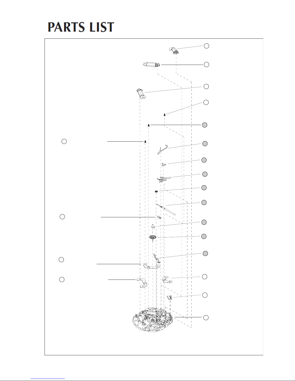
Cal. 7T11A
4002 711
4002 700
4002 700
4146 710
4146 710
4450 703
0383 592
0384 582
0281 580
0351 583
4283 581
0221 583
0391 591
4146 710
0282 586
4239 710
4239 711
4239 712
4450 701
0100 588
28
29
COIL BLOCK
COIL BLOCK FOR
MINUTE COUNTING
COIL
BLOCK FOR
SECONDS COUNTING
30
31
32
33
34
35
36
37
38
39
40
41
42
43
44
45
46
47
ROT
OR FOR
MINUTE COUNTING
ROT
OR FOR
SECONDS COUNTING
SWITCH LEVER FOR ST
ART/
STOP BUTTON
SETTING LEVER
YOKE
SETTING WHEEL
SETTING STEM
ROT
OR
CLUTCH WHEEL
SP
ACER FOR CENTER WHEEL
CENTER WHEEL
TRAIN WHEEL
SETTING
LEVER
ROT
OR STATOR
ROTOR STATOR FOR
SECONDS COUNTING
ROT
OR STATOR FOR
MINUTE COUNTING
SWITCH LEVER FOR
RESET
BUTTON
MAIN PLATE
Lubricating of some parts is shown in “REMARKS ON DISASSEMBLING AND REASSEMBLING.”
[SETTING MECHANISM/STEPPING MOTORS
(STATORS AND COIL BLOCKS)]
6/18
 Loading...