

Page 1
1
ø24.0mm
21.5mm between 6 o’clock and 12 o’clock sides
21.3mm between 3 o’clock and 9 o’clock sides
ø23.3mm
21.5mm between 6 o’clock and 12 o’clock sides
21.3mm between 3 o’clock and 9 o’clock sides
Cal. 7N35C
Cal. 7N36C
PARTS CATALOGUE / TECHNICAL GUIDE
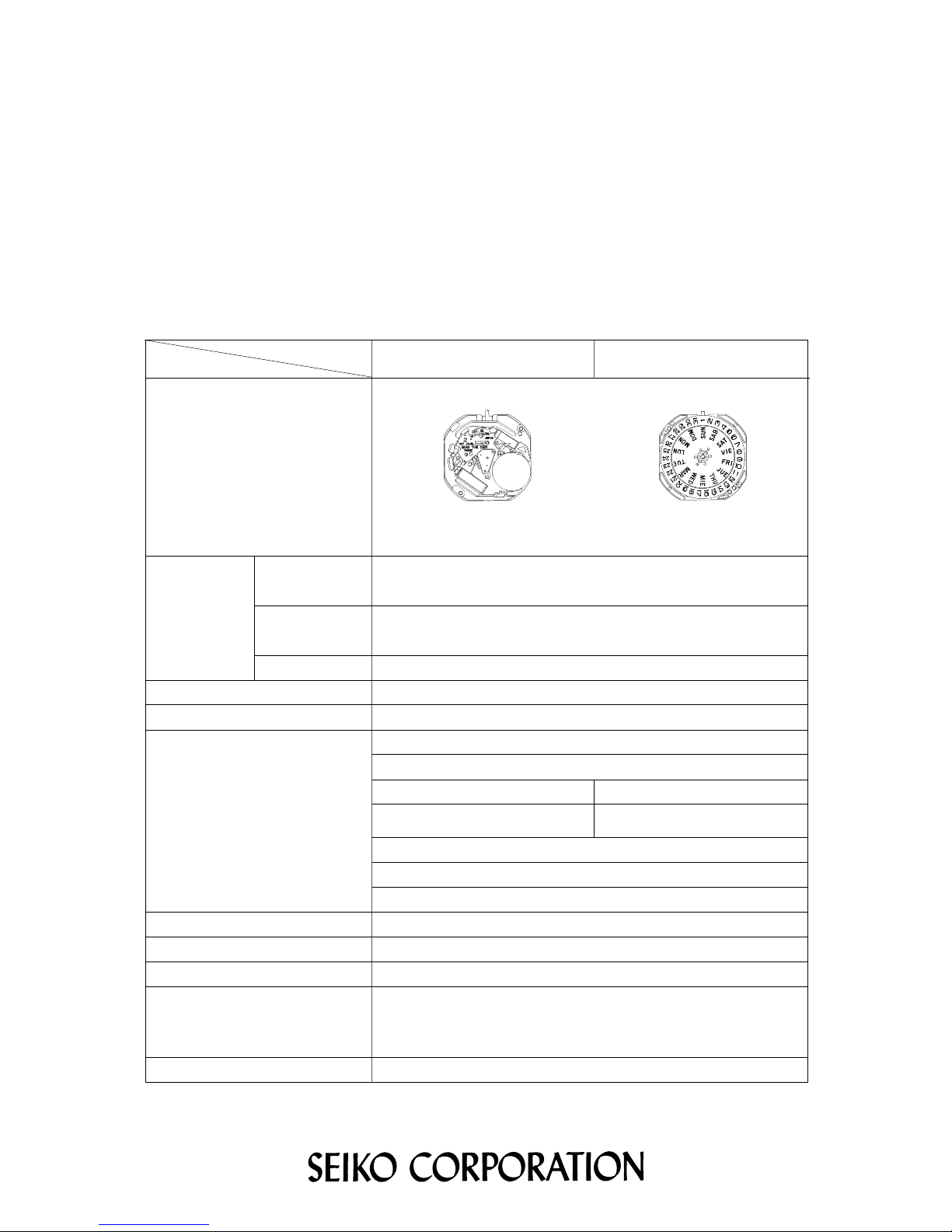
[SPECIFICATIONS]
7N35C
Cal. No.
Item
Movement
7N36C
The illustrations refer to Cal. 7N36C.
(x 1.0)
Outside diameter
Casing diameter
Height 2.78mm
Movement size
Time indication 3 hands
Driving system Step motor (Load compensated driving pulse type)
Additional mechanism
Date calendar
_
Day calendar
_
Jewels 1 jewel
SEIKO SR920SW, Maxell SR920SW, SONY SR920SW,
Matsushita SR920SW, EVEREADY 371
Battery life is approximately 4 years.
Voltage: 1.55V
Battery
Measuring gate by quartz tester
Use 10-second gate.
Regulation system Nil
Monthly rate at normal temperature range: less than 15 secondsLoss/gain
Battery life indicator
Electronic circuit reset switch
Train wheel setting device
Instant setting device
for day calendar
Instant setting device for date calendar
Page 2
2
Cal. 7N35C, 7N36C
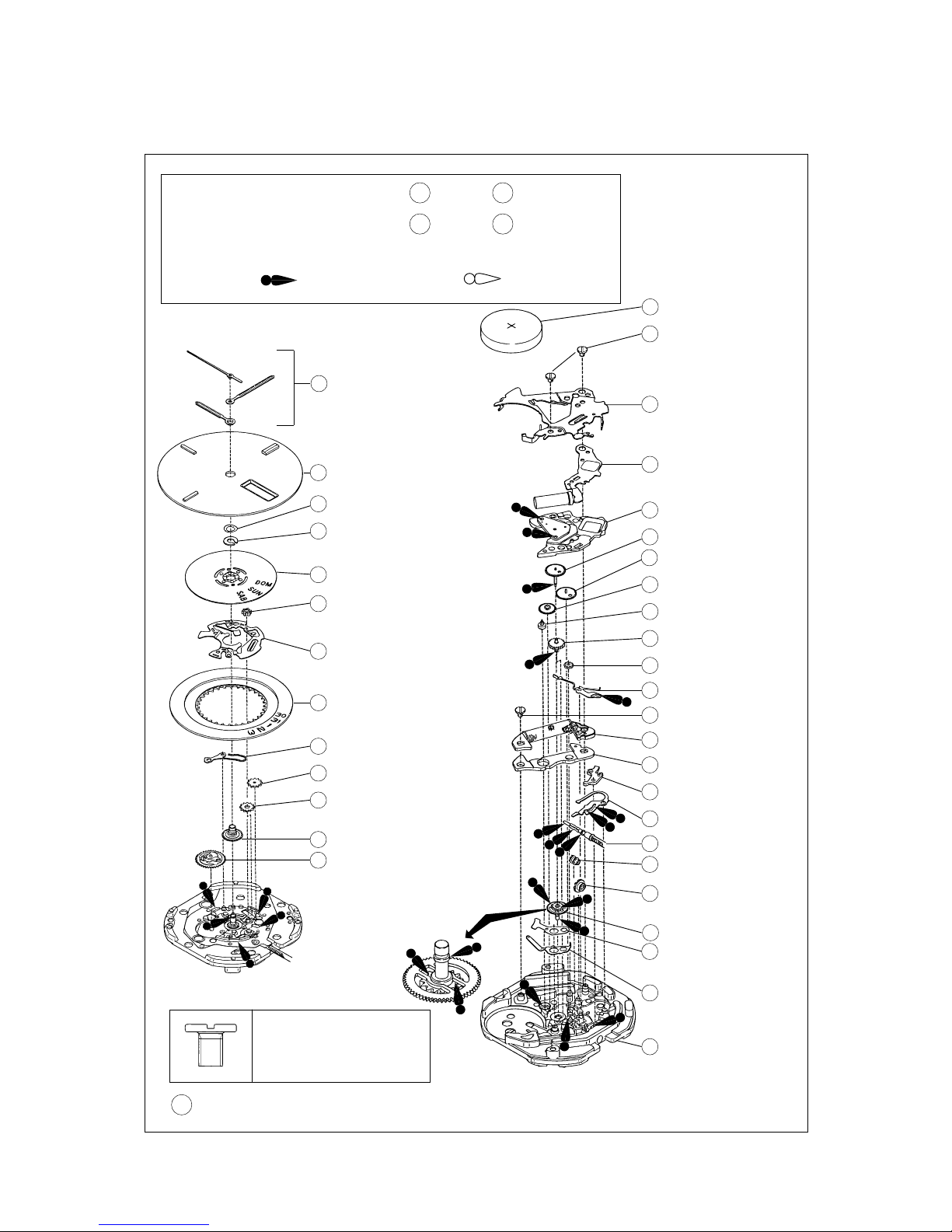
PARTS CATALOGUE
Ex. : Cal. 7N36C
➡➡
Please see the remarks on the following pages.
Disassembling procedures Figs. : 1 → 37
Reassembling procedures Figs. : 37 → 1
Lubricating: Types of oil Oil quantity
Moebius A Normal quantity
0022 247
• Battery connection
(+) screw (2 pcs.)
• Coil block screw (1 pc.)
15 0022 247
Battery connection
(+) screw
1 Hour, minute and
second hands
13 0802 890
Date driving wheel
11 0962 891
Second intermediate wheel
for calendar correction
12 Hour wheel
10 0737 891
Date corrector setting wheel
9 0810 890
Date jumper
8 Date dial
7 0808 890
Date dial guard
6 0989 890
(only for Cal. 7N36C)
Intermediate wheel for
day correction
5 Day star with dial disk
(only for Cal. 7N36C)
4 0963 230
(only for Cal. 7N36C)
Snap for day star
with dial disk
3 0419 735
Dial washer
2 Dial
14 Battery
(See the front page.)
24 0281 904
Setting wheel
23 0261 904
Minute wheel
22 4146 886
Step rotor
21 0701 904
Fifth wheel and pinion
20 0231 904
Third wheel and pinion
19 Fourth wheel and pinion
18 0125 923
Train wheel bridge
17 4000 634
Circuit block
16 Battery connection (+)
25 0391 890
Train wheel setting lever
26 0022 247
Coil block screw
27 4002 923
Coil block
28 4239 892
Rotor stator
29 0383 891
Setting lever
30 0384 890
Yoke
31 Winding stem
32 0282 890
Clutch wheel
33 0962 890
First intermediate wheel
for calendar correction
34 Center wheel and pinion
35 4216 904
Insulator for battery
connection C
36 4270 904
Battery connection (–)
37 Main plate
Page 3
3
Cal. 7N35C, 7N36C
Remarks:
PARTS CATALOGUE
12 Hour wheel
19 Fourth wheel and pinion
34 Center wheel and pinion
37 Main plate
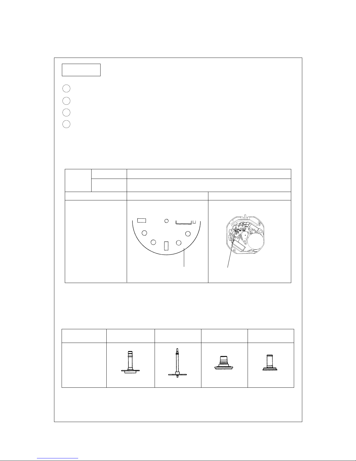
Height
Numeral for
discrimination
Discrimi-
nation
Standard type
2
Dial MovementPrinted on
Ex) Standard type
Ex) Standard type
The numeral is printed at the
right end.
The numeral is printed below
the calibre number.
Printed position
• Discrimination of the hand installation height
Cal. 7N series watches have numerals printed on the dial and the movement to indicate the
hand installation heights. When repairing, refer to the table below.
Combination:
* The hand installation heights can be known from the shape of the following parts. Refer to
the table below.
Hour wheel
0271 934 0100 9430241 9340221 939
2
Main plate
(Center pipe)
Fourth wheel
and pinion
Center wheel
and pinion
Numeral for
discrimination
J
A
P
A
N
7
N
3
6
-
6
A
2
0
R
2
Page 4

4
TECHNICAL GUIDE
Cal. 7N35C, 7N36C
Cal. 7N35C, 7N36C
PARTS CATALOGUE
31 Winding stem 0351 892
The type of winding stem is determined based on the design of cases.
Check the case number and refer to “SEIKO Casing Parts Catalogue” to choose a corresponding
winding stem.
16 Battery connection (+) 4268 620
The battery connection (+) we are supplying has no calibre number nor numeral printed on it for
discriminating the hand installation height.
• The explanation here is only for the particular points of Cal. 7N35C and 7N36C.
• For the repairing, checking and measuring procedures, refer to the “TECHNICAL GUIDE, GENERAL
INSTRUCTIONS”.
I. STRUCTURE OF THE CIRCUIT BLOCK
Input terminal (-)
Crystal unit
Input terminal (+)
C-MOS-IC
Coil output terminal
Page 5

5
Cal. 7N35C, 7N36C
Tweezers
II. REMARKS ON DISASSEMBLING AND REASSEMBLING
Use the universal movement holder for disassembling and reassembling.
1 Hands
• How to install
When installing the hands, remove the battery and
place the movement directly on a flat metal plate or
the like.
6 Intermediate wheel for day correction (only for Cal. 7N36C)
Set the intermediate wheel for day correction in the
direction as shown in the illustration at right.
Main plate side
Dial side
7 Date dial guard
Unlike conventional movements, the date dial guard is not fixed with screws. It is set to the main
plate with the three protrusions, which are caught under the main plate by turning the guard. Then,
it is fixed by the two guide pins.
• How to remove
1) Lightly lift the A portion of the date dial guard
with tweezers to release it from the guide pin,
and then move it in the counterclockwise
direction until it gets on the guide pin.
2) Release the B portion of the date dial guard in
the same way as described above, and then
move it in the counterclockwise direction until
it gets on the guide pin.
3) Check that all the three protrusions of the date
dial guard have come off from the main plate,
and then remove the date dial guard.
TECHNICAL GUIDE
A portion
Guide pin
Protrusion
B portion
Date dial guard
Metal plate
Page 6

6
• How to install
Cal. 7N35C, 7N36C
1) Put the date dial guard on the main plate
so that the A and B portions are over the
guide pins, as shown in the illustrations at
right.
2) Move the protrusion D of the date dial
guard in the clockwise direction so that it
is caught under the main plate.
3) Slightly move the protrusions C and E in
the clockwise direction alternately to set
them under the main plate. Then, set the
A and B portions of the date dial guard to
the guide pins.
4) Check that the date dial guard is fixed
securely to the main plate.
14 Battery
• How to install
Insert the battery aslant from the direction shown by the
arrow.
15 Battery connection (+) screw
Fasten the screw on the crystal unit side while holding down
the edge of the crystal unit.
16 Battery connection (+)
• How to install
Have the hooking portion (2 places) catch the main plate.
In disassembling and reassembling, take care not to deform
the hooking portions.
After installing the battery connection (+), check that the two
hooking portions securely catch the main plate.
TECHNICAL GUIDE
Protrusion D
Protrusion C
B portion
Protrusion E
A portion
Page 7

7
Cal. 7N35C, 7N36C
Winding stemClutch wheel
First intermediate wheel for
calendar correction
Note: Take care not to deform the spring portion of the yoke.
18 Train wheel bridge
• Setting position
Refer to the illustration at right.
25 Train wheel setting lever
29 Setting lever
30 Yoke
• Setting position
TECHNICAL GUIDE
Note: Take care not to damage the wheels made of plastics in disassembling and reassembling.
Refer to the illustrations below.
Center wheel and
pinion
Minute wheel
Fifth wheel and pinion
Step rotor
Third wheel and pinion
Setting wheel
Fourth wheel and pinion
31 Winding stem
The first intermediate wheel for calendar correction has
some elasticity in the contact with the winding stem so
that it can be easily fixed.
Push in the winding stem straight toward the center of
the main plate.
Setting wheel
Minute wheel
Third wheel
and pinion
Fourth wheel
and pinion
Fifth wheel
and pinion
Step rotor
Setting lever
Train wheel setting lever
Yoke
Page 8

8
TECHNICAL GUIDE
III. VALUE CHECKING
• Coil block resistance
Cal. 7N35C, 7N36C
1.18KΩ ~ 1.58KΩ
• Current consumption
For the whole movement : less than 1.20µA
For the circuit block (4000 634) alone : less than 0.28µA
Remarks: When the current consumption exceeds the standard value for the whole movement
but within the standard value range for the circuit block alone, the watch is generating
the driving pulse for compensating for the heavy load that may be applied to the gear
train, etc.
In this case, overhaul and clean the movement parts and then measure current consumption
for the whole movement again.
95-3 Printed in Japan
 Loading...