

Seiko 6A32, 6A32A Parts Catalogue /technical Manual

PARTS CATALOGUE / TECHNICAL GUIDE
Cal. 6A32A
Cal. No.
6A32A
Movement
Movement
size (mm)
Time indication
Outside diameter
Casing diameter
Height
)
Including
battery portion
(
Driving system
Additional mechanism
Loss/gain
Regulation system
Measuring gate by quartz tester
Battery
Battery No.
Voltage
Battery life
Jewels
SEIKO
Brand
Ø 27.8
Ø 27.3
3.69
3 hands (hour, minute and second hands)
Step motor (hour, minute and second hands)
Electronic driving motor for calendar indication
● Fully automatic calendar (No calendar adjustment required at the
end of a month, nor for a leap year)
● Initial position adjustment (Position adjustment for the second hand
and date)
● Train wheel setting device
● Electronic circuit reset switch
● Battery life indicator
Crown
Operation
Normal position
First click position
Second click position
Free
Monthly rate at normal temperature range: less than 20 seconds
Nil.
Use 10-second gate.
Silver Oxide Battery SB-AP (SR927SW)
1.55 V
Approximately 4 years
Nil.
Date, month, year adjustments (by turning the crown either clockwise
or counterclockwise) (electronic system)
Hand position adjustments, Second regulation, Reset switch
2
Cal. 6A32A
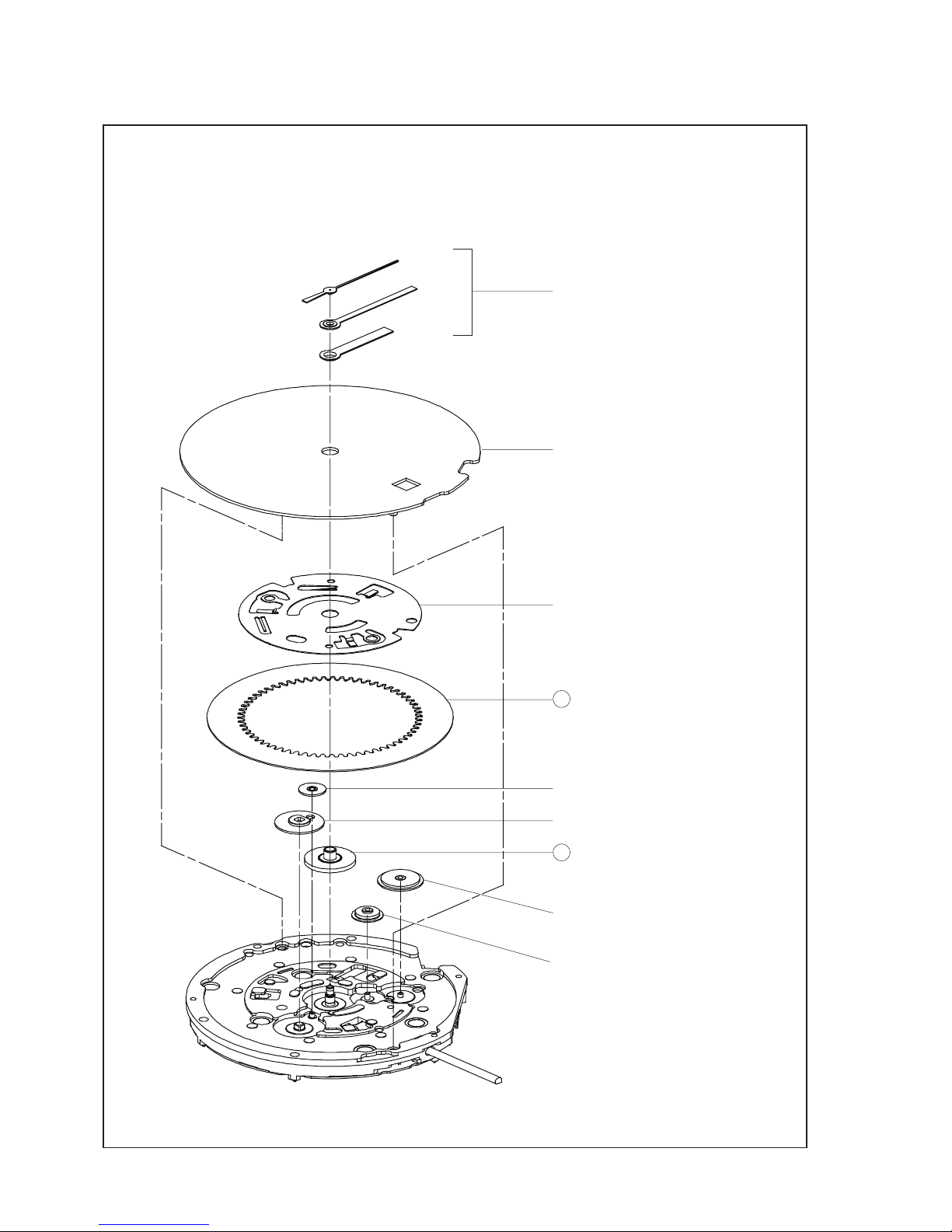
PARTS CATALOGUE
● Order of disassembly for the hands, dial and wheels on the back side
1 HOUR, MINUTE AND SECOND HANDS
2 DIAL
3 DATE DIAL GUARD
0808 051
4 DATE DIAL
5 INTERMEDIATE 24-HOUR WHEEL
0817 046
6 24-HOUR WHEEL
1019 001
7 HOUR WHEEL
0273 031
(for models of the medium hand installation
height)
8 DATE DRIVING WHEEL
0802 035
9 INTERMEDIATE DATE DRIVING WHEEL C
0817 045
3
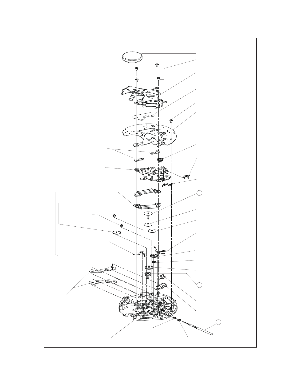
Cal. 6A32A
PARTS CATALOGUE
● Order of disassembly for the battery, circuit block, wheels on the front side and switching mechanism
10 SILVER OXIDE BATTERY
11
POWER SWITCH SPRING SCREWS
0016 121
12 POWER SWITCH SPRING
4245 492
(for models of the medium
hand installation height)
13 INSULATOR FOR CIRCUIT
BLOCK
4216 101
16 CIRCUIT BLOCK SPACER
4408 137
17 24-HOUR ARBOR
1014 023
18 WINDING STEM SWITCH
LEVER
4450 016
19 TRAIN WHEEL BRIDGE
0125 266
14 CIRCUIT BLOCK SCREW
0016 121
15 CIRCUIT BLOCK
4004 104
20 WINDING STEM SWITCH
LEVER SPRING
4238 003
21 FOURTH WHEEL AND PINION
0241 214
(for models of the medium
hand installation height)
22 THIRD WHEEL AND PINION
0231 454
23 FIFTH WHEEL AND PINION
0701 450
24 INTERMEDIATE DATE
DRIVING WHEEL A
0817 043
25 STEP ROTORS
4146 453
26 TRAIN WHEEL SETTING LEVER
0391 027
27 BATTERY CONNECTION(-)
4270 239
28 MINUTE WHEEL AND PINION
0261 451
29 SETTING WHEEL
0281 452
30 INTERMEDIATE DATE
DRIVING WHEEL B
0817 044
31 CENTER WHEEL AND PINION
0221 064
(for models of the medium
hand installation height)
32 COIL BLOCKS
4002 923
34 SETTING LEVER
0383 891
35 YOKE
0384 452
36 WINDING STEM
0351 071
37 CLUTCH WHEEL
0282 452
38 SWITCH CAM
4295 006
39 MAIN PLATE
33 ROTOR STATORS
4239 450
4
Cal. 6A32A
PARTS CATALOGUE
[Parts list]
There are different types of parts which are determined based on the case design or hand installation height.
To choose the appropriate one, refer to “WATCH PARTS CATALOGUE CD-ROM.”
For models of the medium
hand installation height
For models of the medium
hand installation height
For models of the medium
hand installation height
For models of the medium
hand installation height
Inprinted mark "2"
PARTS NAME
DATE DIAL GUARD
DATE DIAL (INCOMPLETE)
INTERMEDIATE 24-HOUR WHEEL
24-HOUR WHEEL
HOUR WHEEL
DATE DRIVING WHEEL
INTERMEDIATE DATE DRIVING WHEEL C
SILVER OXIDE BATTERY
POWER SWITCH SPRING SCREW
POWER SWITCH SPRING
INSULATOR FOR CIRCUIT BLOCK
CIRCUIT BLOCK SCREW
CIRCUIT BLOCK
CIRCUIT BLOCK SPACER
24-HOUR ARBOR
WINDING STEM SWITCH LEVER
TRAIN WHEEL BRIDGE
WINDING STEM SWITCH LEVER SPRING
FOURTH WHEEL AND PINION
THIRD WHEEL AND PINION
FIFTH WHEEL AND PINION
INTERMEDIATE DATE DRIVING WHEEL A
STEP ROTOR
TRAIN WHEEL SETTING LEVER
BATTERY CONNECTION(-)
MINUTE WHEEL AND PINION
SETTING WHEEL
INTERMEDIATE DATE DRIVING WHEEL B
CENTER WHEEL AND PINION
COIL BLOCK
ROTOR STATOR
SETTING LEVER
YOKE
WINDING STEM
CLUTCH WHEEL
SWITCH CAM
MAIN PLATE
TOTAL NUMBER OF PARTS (TO BE ASSEMBLED)
Refer to WATCH PARTS
CATALOGUE CD-ROM.
PARTS CODE
0808 051
-
0817 046
1019 001
0273 031
0802 035
0817 045
0016 121
4245 492
4216 101
0016 121
4004 104
4408 137
1014 023
4450 016
0125 266
4238 003
0241 214
0231 454
0701 450
0817 043
4146 453
0391 027
4270 239
0261 451
0281 452
0817 044
0221 064
4002 923
4239 450
0383 891
0384 452
0351 071
0282 452
4295 006
0100 293
SB-AP (SR927SW)
(11)(12)(13)(14)
(33)
Refer to WATCH PARTS
CATALOGUE CD-ROM.
No.
3
4
5
6
7
8
9
10
11
12
13
14
15
16
17
18
19
20
21
22
23
24
25
26
27
28
29
30
31
32
33
34
35
36
37
38
39
1
1
1
1
1
1
1
1
4
1
1
1
1
2
1
1
1
1
1
1
1
1
2
1
1
1
1
1
1
2
2
1
1
1
1
1
1
44
REMARK
Number
of parts

5
TECHNICAL GUIDE
Cal. 6A32A
1. How to pull out the winding stem
With the crown at the normal position, using a tool
such as a pair of tweezers, press down the
designated area indicated by “PUSH” (as shown in
the illustration on the right) of the setting lever. And
then, pull out the winding stem to which the crown
is attached.
DISASSEMBLY
2. How to remove the hands
Reassemble the winding stem. Turn the hour, minute and second hands to align them pointing in the
same direction, and then remove them all together.
When using a tool such as a hand remover, exercise care so as not to damage the calendar frame or the
dial with the tool during the hand removing process. Align the hands together at a position where you
can avoid touching the calendar frame with the tool, in consideration of the orientation of the calendar
frame on the dial.
To prevent damage to the surface of the hands and dial, slip a thin plastic sheet between the dial and
remover.
3. How to remove the dial
From the lateral side at the foot positions of the dial
(indicated in the illustration on the right), insert the
tip of a driver or tweezers into the gap between the
lower surface of the dial and main plate to gradually
lift up the dial and remove it.
While doing this, make sure to lift the dial up
gradually one side after another. Lifting the dial up
only from one side may break the foot of the dial.
For disassembly and reassembly, make sure to use the all-purpose
movement holder.
Designated area of the setting stem
Foot positions of the dial
6
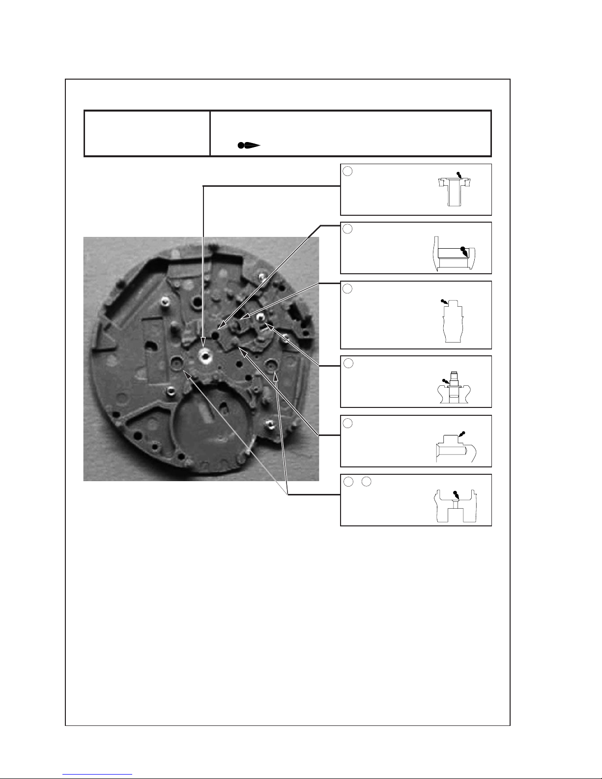
TECHNICAL GUIDE
Cal. 6A32A
Installation positions • Lubrication points • Remarks
Reassembly (1)
Lubricate the main plate.
❇ Make sure to lubricate the exact lubrication points with an adequate
amount of the correct type of oil.
normal quantity
Main plate (back side)
1 Center pipe (AO-3)
2 Lower guide hole of the minute wheel
and pinion (AO-3)
3 Guide pin of the train wheel setting
lever (AO-3)
4Pin of the setting lever (AO-3)
5Pin of the setting wheel (AO-3)
6 & 7 Lower holes of the rotor (AO-2)
7
TECHNICAL GUIDE
Cal. 6A32A
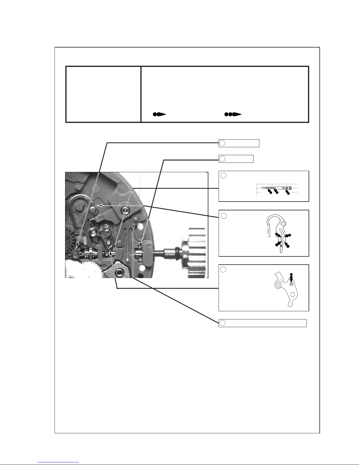
Reassembly (2)
Lubricate the switching
mechanism.
❇ Install the parts in the number order shown in the illustration below,
paying attention to the following:
mounting positions,
direction of mounting,
type of oil, lubrication point(s) and amount of lubrication.
normal quantity
liberal quantity
Installation positions • Lubrication points • Remarks
1 Clutch wheel
5 Setting lever (AO-3)
2 Switch cam
6 Winding stem switching lever spring
3 Winding stem (AO-3)
4 Yoke (AO-3)

8
TECHNICAL GUIDE
Cal. 6A32A
Installation positions • Lubrication points • Remarks
Reassembly (3)
Reassemble the wheels and
train wheel bridge.
❇ Install the parts in the number order shown in the illustration below,
paying attention to the following:
mounting positions,
direction of mounting,
type of oil, lubrication point(s) and amount of lubrication.
normal quantity
7Setting wheel
8 Minute wheel and pinion
10 Rotor
11 Rotor
9 Battery connection (-)
1 Rotor stator
2 Rotor stator
3 Coil block
4 Coil block
12 Fifth wheel and pinion
13 Intermediate date driving wheel A
14 Third wheel and pinion
6 Intermediate date driving wheel B
5 Center wheel and pinion (AO-3)
 Loading...