

Page 1
Operating Instruction
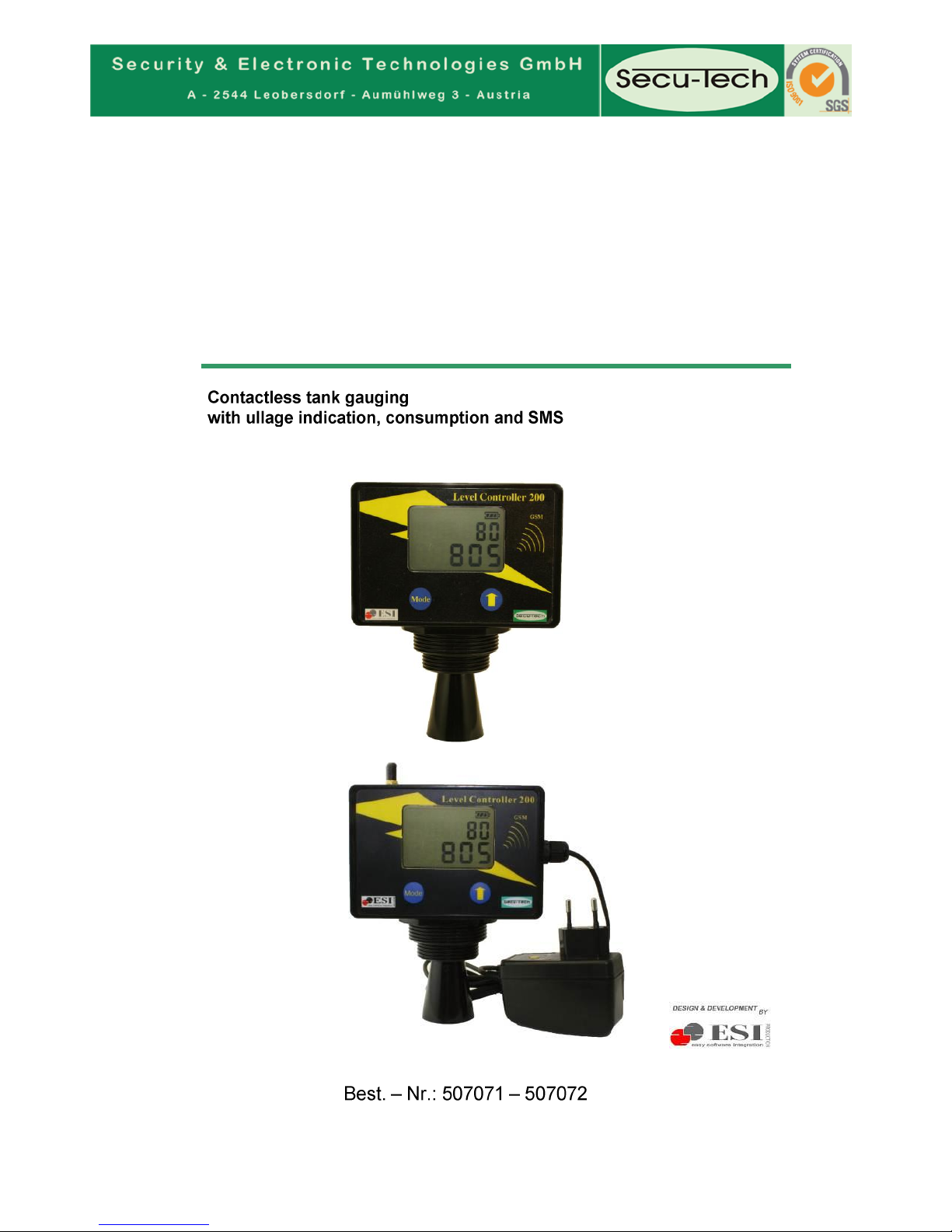
LC200 –Level Controller 200
LC 201 – Level Controller 201
SW 02.57
05 2012 LC 2 E M 07_C
Page 2

Security & Electronic Technologies
Seite 2
Directory
Safety Instruction 2
Product Description 3
Installation Instruction 3
Checking the contents of delivery 4
1,Operating Tools 5
2. Configuration 6
Operating 7
Reset : 7
Re Reset: 7
Your Tank Data´s Display 8
Error Measurement 8
Error GSM Mode 8
Additional application with external mains power supply LC201 9
Maintenance, Troubleshooting, Service 11
See the GTCS – General Terms and Conditions of Sale 11
Datum: 05 2012
Dokument: LC2 E M 07_C
Important:
The technical specification stated in this document is subject to modification by the
manufacturer without any notice!
Safety Instruction
Important: LC must not be installed in a hazardous environment and must not be used for the following
liquids: Gasoline, Ethanol, aggressive chemical products like acids and aggressive chemicals.
Improper use and any resulting damages the manufacturer cannot take any responsibility.
Modifications on the product are prohibited.
Service repair and maintenance shall be done by the manufacturer or authorised service facilities only.
LC cannot not be used as an overfill prevention system.
The LC gives no security against the tank becoming empty.
Please, read this document carefully before the installation of LC.
© SECURITY & ELECTRONIC TECHNOLOGIES GmbH
Address: Aumühlweg 3/1
Ort: A-2544 Leobersdorf
Telefon: +43 2256 201 77
Fax: +43 2256 201 77 11
Internet: www.secu-tech.at
E-Mail: office@secu-tech.at
Page 3

Security & Electronic Technologies
Seite 3
Product Description
Main advantages:
- Tank contents in litres and volume percent
- Ullage display (how many litres can be delivered)
- Calculation of average daily demand in litres/day
- Calculation of the remaining days based on average daily demand
- 3 different tank shapes are supported by appropriate calculations
Easy Installation
No moving components in the tank
Contactless measurement with ultra sonic pulses for optimal reliability
temperature
Applications:
heating oil tanks
waste oil tanks
water tanks
rainwater tanks
as a replacement for mechanical gauge indicators
…….
Installation Instruction
- Before you make a purchase please check for possible problems at the installation,
- Discuss on the phone, write, and e-mail or use the possibility of an individual meeting with our
field staff.
- Use the device only in the right ambient conditions (read the specifications).
- The device must not be installed in a hazardous environment (94/9/EG)
- If the device is installed too near to a wall, it is possible that reflections
can cause problems to the measurement, because of the characteristic of
the ultra sonic pulses are reflected off the wall.
- The device should be installed in the middle of the tank, as indication you
should install at least a min. distance of 5 cm from the wall to the aperture.
- The indicator should be in a position where the ultra sonic pulses can beam unhindered to the
bottom of the tank.
- Built- in parts can disturb the ultrasonic pulses and may result a false measurement (e.g. pipe,
manhole, cross beam).
- Check the installation situation when the tank is empty, because if the tank is full you cannot
see the built-in parts which can reflect the ultra sonic pulses.
- The calculated medium value (will be calculated by the measured distance) always relates to
the level of the sensor inside of the cone (this sensor is situated at the height of the bigger
external thread).
- The distance between medium level and sensor can be adjusted with the offset.
- The device has a min. and max. Measurement range (look at the specifications), if you work
beyond this specifications you will get wrong or no data.
- For a correct measurement you have to consider that the distance from the sensor to the
maximum filling level is not lesser as the min. measurement range.
- The device must be installed perpendicular to the fluid surface, because otherwise the reflected
ultra sonic pulses can´t be received.
- The sensor and the controller are not allowed to contact the medium which
you want to measure.
- Be sure, that your tank manufacturer allows the installation
and the tank has a minimum entry of 1.5 inch, ideally 2” BSP thread.
-
Page 4

Security & Electronic Technologies
Seite 4
- The mathematical calculation in the LC device is designed only for cylindrical and cubic tank
types, special shapes can´t be considered.
- Only a specialist licensed company is allowed to modify the tank,
in case there is a need to drill or cut holes in the tank! –
you lose the warranty and in case of damage you are personally liable.
- Wrap the thread with Teflon tape to ensure a good seal with the tank.
- If the tank is refuelled (actual tank contents is higher than the value from the day before) the
statistics (average day demand, remaining days) are reset automatically.
- Please note that the battery life of the device depends from settings like permanent display and
measurement in the test mode.
- The LC is a simple device, which helps you to measure tank contents.
This is an electronic device and so it is possible to get an error so that the display shows wrong
values. Always monitor the system to ensure it provides correct data and allows you to ensure
manage your stocks to avoid problems, e.g. an empty tank.
- Take the time (which you have saved with the LC device) and control the tank continuous, so
that it is always in good order and condition.
- Please note the legal requirements for your tank and if you have concerns ask a license
specialty company.
- Always take a look to the service intervals of your tank and a specialist licensed company
should advise you, that your tank meets the legal requirements (e.g. heating oil tanks should be
equipped with a limit indicator for working with overfill protection system
- For using the SMS-function it is necessary that a sufficient telephone network is available. If the
signal from the telephone network is bad (no signal) then the LC200 hasn´t the possibility to
send a SMS.
Checking the contents of delivery
Please, check the contents of delivery immediately after receipt and unpacking.
In case of missing components or transport damages contact your local dealer
or our representative.
Hint: Please keep the original packing material if you have to send the instrument to a service
facility. Keep these operating instructions in case you hand over the instruments to another
person.
LC 200:
Unit LC 200,
Installation Instructions
Page 5
Security & Electronic Technologies
Seite 5
1,Operating Tools
Start Up
- insert 4 batteries
- insert SIM-Card into GSM Modem
Caution: SIM-card must not be protected!!!
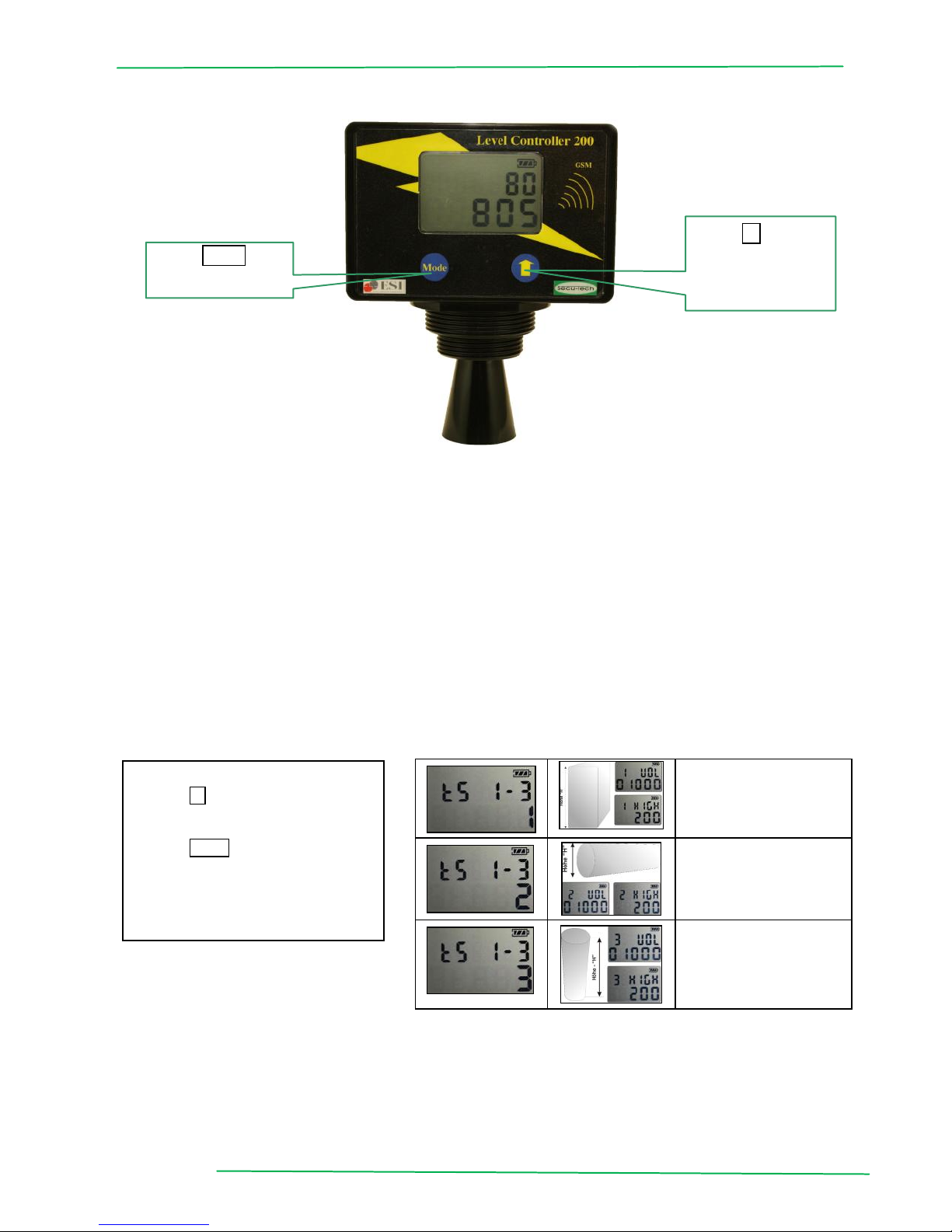
Button functionality:
LC 200 has 2 different buttons:
- "Mode" = a, change functions
b, Wake - up function (power safe modus)
- "Arrow” = increment the selected digit (blinking) by one
Standard mode: to get a new measurement, press the arrow button
No data´s will be stored if the measurement was launched by pressing the
arrow button.
Selection of Tank Type (1, 2, or 3)
Start from the standard display , press mode button 3 sec. SET UP Starts.
Tank Typ1:
cubic
defined by height and
tank capacity
Tank Type 2:
Cylindrical horicontal,
defined by height and
tank capacity
Tank Type 3:
Cylindrical vertical,
defined by height and
tank capacity
Button Mode:
Display selection
Button ▲:
Set up and
Changing values
Hint:
Button ▲: by pressing the
selected digit (blinking)
figure increment by one
Button Mode: save actual
adjustment – next data block.
The selected tank type
is blinking in the right bottom
corner:
Page 6

Security & Electronic Technologies
Seite 6
2. Configuration
tank
volume
Enter tank volume
in litres
Type of tank is shown
in upper left corner
Tank height „H“
Enter tank height
in cm
Type of tank is shown
in upper left corner
Offset
Distance between
sensor to the
maximum tank level
Distance measurement
for e.g. manhole pit or
mounting hole
Alarm
(min.)
Limit for alert in
percent
When Limit is reached
an alarm SMS will be
launched.
Alarm
(max.)
Limit for alert in
percent
When Limit is reached
an alarm SMS will be
launched.
Power safe
Default is 0, the
display is turned
off after 35 s
0 Default
1: continuous display
date
mm/dd
Current Date
Month and day
April 1st - 0401
date
year
Current year
e.g.:2009
Time
Current time
Hours and minutes
0757
Instant of time
Measurement
Time (daily)
e.g.: at 07:30 h
measurement is made
by LC200
GSM
Mode
GSM Mode
1 :GSM enable
0: GSM disabled
to operated settings
GS sen
SMS frequencies
1 = every 7 days
2 = every 14 days
Tel.No.:
Receiver 1*
Telefon Number
Recipient No.1
Any modification
e.g.0167 78787787
or 0044 167 7878787
Tel.No.:
Receiver2*
Telefon Number
Recipient No. 2
First digit 0,
no second recipient
*) after last digit appears zero 0, press arrow button ▲ until no figure appears.
New Configuration on SMS function causes SMS messages for 7 days. Throughout that time
no alarm message is sent.(only if the alarm is confirmed the second day)
Daily SMS:
To adjust the daily text message, press the button on the default display mode for longer than 10 seconds.
SETUP GS Day On on display appears. - The daily tank gauge mode is now active.
Page 7

Security & Electronic Technologies
Seite 7
Operating
First Setting
After inserting the batteries, the device is immediately activated and performs a
measurement.
Reading on display :
Software Serial number Measurement Percent/Litres Actual Date / Time
Reset :
To start a “Reset” press simultaneous the “Mode” and “Arrow “button.
Re Reset:
After 50 seconds the device will automatically turn off. (Sleep mode)
To make you familiar with the device we recommend to make some measurements outside the tank. Hold the funnel with a 90°
against a plain surface ( floor , wall , or ceiling etc.) and press the arrow button to launch your first experience.
Mounting / Installation
LC 200 / 201 is equipped with two threads. 1,5 Inch (6/4“) und 2 Inch thread.
Use a free thread on top of the tank.
Take care that there is no obstacle between sensor and tank level for free ultra sonic beam.
Notice for your installation Parameters / Tank Setting
Tank Type
Height cm
Offset cm
Minimum Alarm
Maximum Alarm
Date
Time
Measurement
GSM Modus
GSM frequency
Tel No. 1
Tel No. 2
Press once more the arrow button all statistical data will be deleted.
All manual installed data remains.
Remove batteries all statistic data´s will be deleted.
All manual installed data remains.
Page 8

Security & Electronic Technologies
Seite 8
Your Tank Data´s Display
Press Mode once the last current measurement is displayed.
Error Measurement
Error GSM Mode
Display
Operating mode, description.
Standard
Tank content in percent
Tank content in Litres.
Proceed with Mode
Tank content in percent
Up to 99.999 Litres
Proceed with Mode
Tank content in percent
Proceed with Mode
Ullage
How many litres can be filled for full tank
Proceed with Mode
Measured depth
Distance from Sensor to surface in cm
Proceed with Mode
Average daily consumption
litres per day (last 10 days)
Proceed with Mode
Number of remaining days
Based on average consumption
Available after 10 days , before the error symbol E appears
Proceed with Mode
Temperature in °C
Temperature inside LC200 device
Proceed with Mode
Full : distance sensor to sureface below 20 cm
Error code figures from 0 to 3
0 – no error
2 – no correct measurement check LC 200
position.
90° to surface is a must.
3 –measurement result not logical – check
settings. Measured depth is higher than setup
value
instead of the default display
appears E error has occurred The number on right side
0 = OK
1 = no answer from the GSM Module
2 = no registration into the network possible
3 = not possible to send the SMS to 1. receiver
4 = not possible to send the SMS to 2. receiver
7 = SMS was not sent to both recipient
8 = the GSM-module can't receive data from the
processor
9 = the LC lost the network registration during sending
the SMS
Page 9

Security & Electronic Technologies
Seite 9
Additional application with external mains power supply LC201
1, LC201 can perform measurements with short time intervals.
"Sen GSM" ** the setting has two additional functions:
4 = measured every 2 hours
5 = measurement every 10 seconds
Note: Alarm or error text will be sent only if a limit has been exceeded or undershot.
Important:
LC201 performs a measurement only if the registration was successful in the GSM network.
(Antenna icon with at minimum two strokes).
If SIM card is not inserted, the LC201will not take any measurements.
Alarm SMS is sent only after 7 days and only if the alarm is repeated on two consecutive
days.
Daily SMS:
To set the daily text message, press the button on the default display mode for longer than
10 seconds. It is first setup and then GS Day On display at the display. The daily SMS is now
activated.
To reinstall daily SMS press the button again 10 sec.(GS DAY OFF)
2, Current Remote Tank Contents Measurement
A current remote tank content measurement can be taken at anytime.
Send a text massage M from your mobile or PC. The LC 201 will take a new measurement
immediately and send a return SMS with the current measurement.
For remote measurement: GSM must be registered.
LC 201 sends back to all registered phone numbers!!
Remote control tank configuration
Create a SMS on your cellular phone with the following format :
The S-Message below is an example with some given Settings (If the LC has received the SMessage, it will immediately send back a SMS with the new parameters)
S1,2000,150,12,25,85,0,0318,2009,1435,1605,1,0,41794235660,0,
(The S-Message is received if the GSM is active, means the antenna symbol is ON
1, - Shape of tank (1=rectangular/2=horiz.cylindric./3=vert.cylindric.)
2000, - Volume in liters
150, - Height or diameter
12, - Offset (Distance between ultra sonic sensor to max. level)
25, - Minimal Level Alarm
85, - maximal Level Alarm
1, - Power Save (0 = ON (default) 1 = OFF
0318, - date 18.03.
2009, - year
1435, - current time 14:35h
1605, - time of measurement ((at the same time the SMS will be sent)
1, -GSM Modus 0 = OFF 1 = ON
0, - GS sen: interval period to send the Control-SMS
0=each 28th of the month / 1=weekly / 2=2 weeks)
415677.. - phone number 1st receiver
4917089... - phone number 2
nd
receiver
(if the first digit of a phone number is 0 –Zero -, the number is not valid
SMS will not send.
- Important : If you want to keep the value of a certain field, you can just substitute it with ,x,
S1,x,x,x,x, 75,x,x,x,x,0800,x,2,x,0
Page 10

Security & Electronic Technologies
Seite 10
Change telephone numbers (T-Message)
T-message = change remotely the telephone numbers of the receivers
T+4179303xxxx,+0, (the first Number is set, the second Number ,+0, is OFF)
T+0,+4170303xxxx, (the first Number is OFF, the second Number is set)
T+491715672xxx,+4179303xxxx, (both numbers are set)
- the setting "GSM sen" has two additional functions:
.
SMS Function
If you use the SMS function, the LC200 will send at the first 7 days a test SMS at the adjusted time,
after the 7 days the SMS will be send at the adjusted configuration (every 28th of each month, every
7 days, every 14 days)
Test SMS: set in the configuration mode the measurement time 2min after the actual time – exit
the configuration mode – after 2min the LC200 launches a measurement and send a SMS.
SMS Massage
Message order (figures as examples)
00805 = tank content in litres
00080 = tank content in percent
00195 = ullage in Litres
0001 = average consumption last 10 days 805 = remaining days
039 = measured distance in cm
022 = ambient temperature in Celsius
062 = Battery Voltage (example digit is 57 = 5,7 Volt)
010 = GSM signal strength
(21-30 = very good / 7-20 = good/ 1-6 = weak / 0 = no coverage)
01.04.09 = date
07.30 = current time
0 = Level measurement error code (see page15)
0 = GSM error code (see page 15)
02. 54 = SW Version
1170 = device ID (serial number)
00000 = SMS ID
LC200
1 = set tank type
01000 = set tank content in litres
200 = set tank height or diameter in cm
00 = set offset in cm
20 = set min. alarm level
90 = set max. alarm level
0 = set PS (Power Save)
1 = set GS sen (sending frequencies )
1 = set GSM mode
Page 11

Security & Electronic Technologies
Seite 11
Maintenance, Troubleshooting, Service
The device does not need any maintenance.Clean the inside of the sensor cone once a year with a
dry cloth to avoid dirt and debris which could influence the beam of the ultra sonic pulses.
Make a visual check of the batteries once a year. Depending on the charge of batteries you have to
change them.
If the device shows unexpected behaviour try to reset the instrument using the Reset button.
Check your installation (look at the instructions for installation).
If the problem persists contact our service team or send the device to an authorised service facility.
If the device is damaged, remove it immediately from your tank and send it to an authorised service
facility.
If the device is removed close the tank entry after that so that the vapours can´t escape.
Technical Data
LC 200
Dimension (w x d x h): 130 mm x 65 mm x 160 mm
LC 200 Battery: 4 pcs. 1,5V, Baby, Type C , Alkali
Battery life time: appr. 3 years in power safe modus at room temp.
LC 201
Power Supply 230 / 50 Hz
LC 200 / 201
Housing: IP 65
Display: 2 line LC-Display 60 mm x 40 mm
Weight 440g
Material ABS
Measurement range: 19 cm - 270 cm, 0 - 99.999 Liter
Accuracy: ±1 cm
Measurement intervals: 24h
Operating temperature: -10°C ... +45°C
Engineering standards: CE, ROHS
Threads 1 ½” and 2”
Warranty
For the actual services and conditions see our home page www.secu-tech.at,
See the GTCS – General Terms and Conditions of Sale
 Loading...