

Securitron SMLS, SMSS Installation Instructions
Securitron Magnalock Corp. Tel 775.355.5625
550 Vista Boulevard Fax 775.355.5633
Sparks, NV 89434 info@securitron.com
www.securitron.com
ASSA ABLOY, the global leader
in door opening solutions
INSTALLATION INSTRUCTIONS FOR
SMLS/SMSS
Surface Mount Lock Shear & Surface Mount Strike Shear
1. INTRODUCTION
Securitron’s model SMLS and SMSS are accessory mounting brackets designed to provide
optional surface mounting of the SAM (Shear Aligning Magnalock). The SMLS assembly consists
of a two-part housing and associated hardware for the surface mount of the (SAM) Magnalock
body. The SMSS assembly includes the housing and hardware for the surface mount of the
(SAM) strike armature. The SMLSM and SMSSM are the metric versions of these same brackets.
These custom brackets allow the Magnalock body and/or the strike armature to be mounted in a
wide variety of configurations while maintaining the integrity and holding force of the SAM.
2. SPECIFICATIONS
SMLS (& SMLSM):
Dimensions: 12.40” X 2.13” X 1.45”
(314.9mm X 54.1mm X 36.8mm)
SMSS (& SMSSM):
Dimensions: 12.40” X 2.13” X 1.45”
(314.9mm X 54.1mm X 36.8mm)
3. PRODUCT OVERVIEW
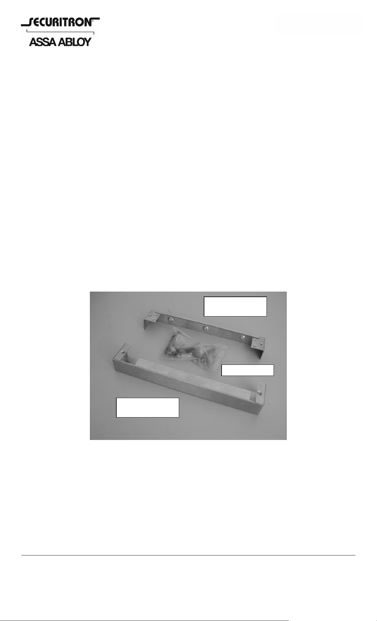
Upon unpacking this product, an inventory should be made to ensure that all the required
components and hardware have been included. Along with these instructions, this product
should include the following items:
Enclosure Mount
Bracket
Hardware Pack
Enclosure Cover
Bracket
(A complete list of all included parts is provided in Sections 5.2 and 5.3 of these instructions).
4. RECOMMENDED TOOLS
Drill Motor
Drill Bit: 3/8” [9.5mm]
Screwdrivers: Phillips and Standard
Measuring Tool (ruler or tape measure)
Hex (Allen) Wrenches: 1/8” (provided in Metric Hardware Pack), 5/32” [4mm] and 3/16”
Blind Nut Installation Tool (provided with SMSS/SMSSM only)
© Copyright, 2007, all rights reserved PN# 500-12400
Page 1 Rev. B, 7/07
5. INSTALLATION INSTRUCTIONS
5.1. Pre-Installation Survey/Assessment
Due to the wide variety of mounting configurations available with these products, it is
strongly recommended that an initial survey and assessment be made of the physical area to
which the Magnalock will be installed. A determination of the optimal method of mounting
should be made prior to installation. The SAM Lock, which these brackets are intended to be
used with, is considered as primarily an access control device and thus will normally be
installed on the “secure” side of the door. Therefore, protection of the lock from external
attack or vandalism is not generally a concern. Structural integrity of the mounting surface,
convenience and accessibility should be considered however, and the assembly should be
installed in a location that will not hinder or create a potential safety hazard to authorized
personnel routinely accessing the area.
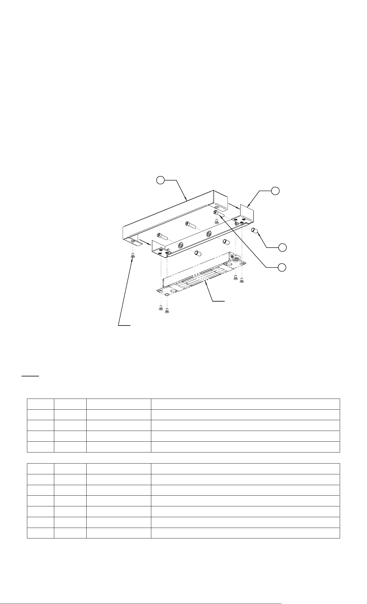
5.2. Magnalock Installation using SMLS/SMLSM
Figure 1 below is an exploded illustration of the general SAM lock mounting configuration
available using the hardware provided:
2
1
4
3
(REFERENCE) SAM LOCK
- NOT INCLUDED
(6) 10-32 UNF X 3/8" LONG
FLAT HEAD SOCKET SCREWS
SUPPLIED WITH SAM LOCK OR
METRIC (SMLSM) VERSION OF
LOCK MOUNT
Figure 1
Note: The items represented by the phantom/dashed lines are for reference only – the SAM
Magnalock and its associated hardware are NOT included with this product.
U.S. Standard:
ITEM QTY PART NUMBER NOMENCLATURE/DESCRIPTION
1 1 370-14100 Lock/Strike Mounting Bracket
2 1 370-14120 Lock/Strike Bracket Cover
3 3 300-12400 1/4-20 UNC X 1” Long Socket Head Cap Screw
4 3 320-10800 1/4-20 UNC Blind Nut, 1-Piece, Steel
Metric:
ITEM QTY PART NUMBER NOMENCLATURE/DESCRIPTION
1 1 370-14100 Lock/Strike Mounting Bracket
2 1 370-14120 Lock/Strike Bracket Cover
3 3 300-12390 M6-1.0 X 25MM Long Button Head Socket Cap Screw
4 3 320-11050 M6-1.0 Blind Nut, 1-Piece, Steel
5 6 300-12160 10-32 UNF X 3/8” Long Flat Head Socket Screw
6 1 350-10250 Hex Wrench, 1/8”
PN# 500-12400
Page 2 Rev. B, 7/07
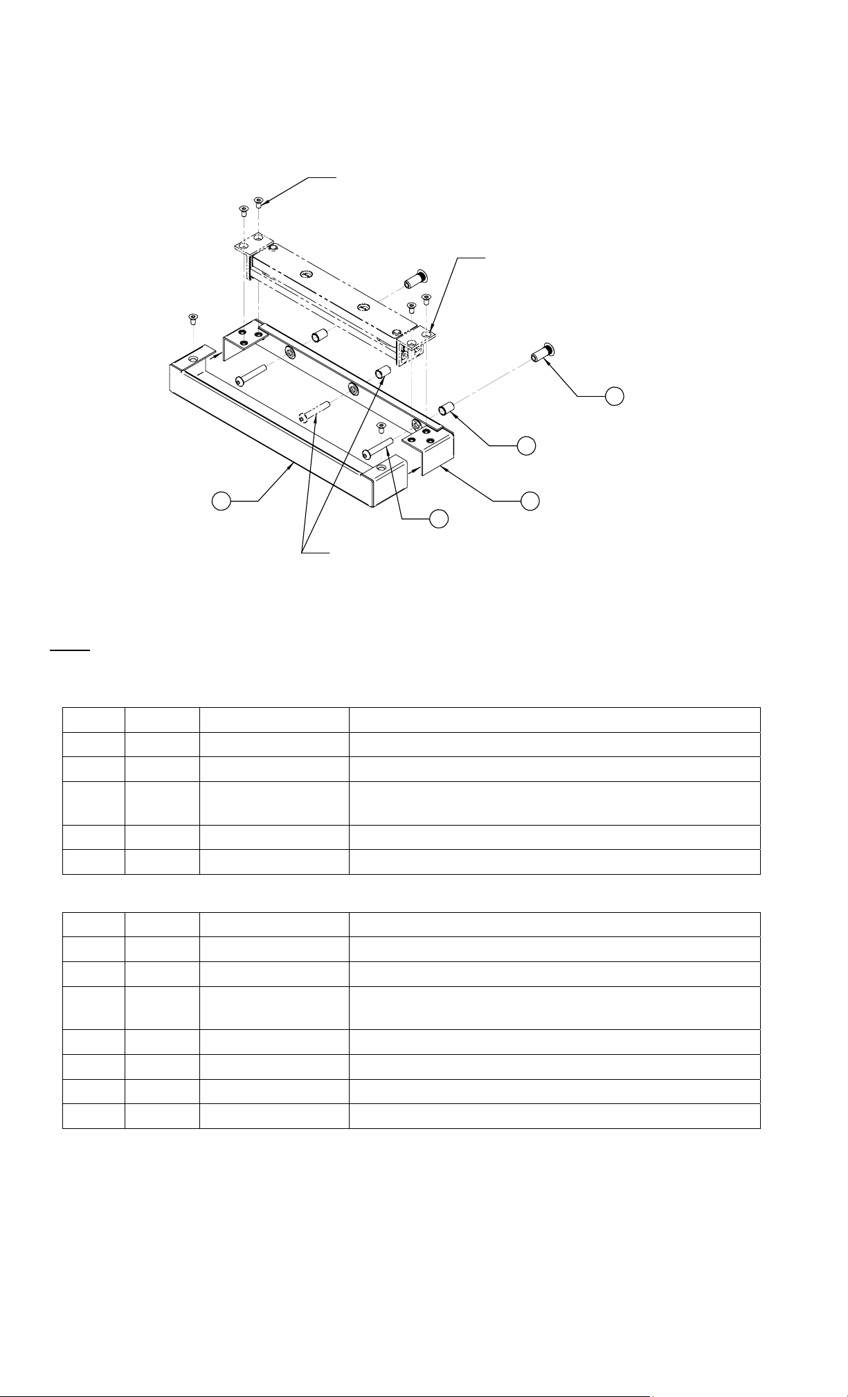
5.3. Strike Armature Installation using SMSS/SMSSM
Figure 2 below is an exploded illustration of the general strike armature mounting
configuration available using the hardware provided:
(6) 10-32 UNF X 3/8" LONG
FLAT HEAD SOCKET SCREWS
SUPPLIED WITH SAM LOCK OR
METRIC (SMSSM) VERSION OF
STRIKE MOUNT
(REFERENCE) SAM STRIKE
ARMATURE - NOT INCLUDED
5
4
2 1
3
(OPTIONAL) - CENTER HOLE OF
BRACKET MAY ALSO BE USED
FOR MOUNTING IF NECESSARY
Figure 2
: The items represented by the phantom/dashed lines are for reference only – the SAM
Note
Strike Armature and its associated hardware are NOT included with this product.
U.S. Standard:
ITEM QTY PART NUMBER NOMENCLATURE/DESCRIPTION
1 1 370-14100 Lock/Strike Mounting Bracket
2 1 370-14120 Lock/Strike Bracket Cover
3 3 300-12417
1/4-20 UNC X 1-1/2” Long Button Head Socket
Cap Screw
4 2 320-10800 1/4-20 UNC Blind Nut, 1-Piece, Steel
5 2 330-12100 Sex Bolt, 1/4-20 UNC X 1” Long, Steel
Metric:
ITEM QTY PART NUMBER NOMENCLATURE/DESCRIPTION
1 1 370-14100 Lock/Strike Mounting Bracket
2 1 370-14120 Lock/Strike Bracket Cover
3 3 300-12432
M6-1.0 X 40MM Long Button Head Socket Cap
Screw
4 2 320-11050 M6-1.0 Blind Nut, 1-Piece, Steel
5 2 330-12150 Sex Bolt, M6-1.0 X 25MM Long, Steel
6 6 300-12160 10-32 UNF X 3/8” Long Flat Head Socket Screw
7 1 350-10250 Hex Wrench, 1/8”
PN# 500-12400
Page 3 Rev. B, 7/07
 Loading...