

Page 1
Securitron Magnalock Corp. www.securitron.com ASSA ABLOY, the global leader
Tel 800.624.5625 techsupport@securitron.com
in door opening solutions
SHEAR ALIGNING MAGNALOCK MODEL SAM
INSTALLATION AND OPERATING INSTRUCTIONS
1 INTRODUCTION
Securitron’s Shear Aligning Magnalock “SAM” is intended for installations where concealed
mounting in the door and frame is desired. The operating features allow self-alignment while
securing the door when it closes. The SAM is designed to operate with one-way swing, bidirectional swing or sliding type doors. The lo ck is also capable of securing bi-parting motorized
sliding doors. On swing type doors the lock installs horizontally in the top or bottom of the door
frame or may be installed vertically in the door frame side. For slider type door applications the
locks must be installed horizontally for proper operation. These units have also been designed to
unlock even if a preload is applied to the door.
The SAM BondSTAT “B” Series, Bond Sensor, monitors the magnetic field. An internal sensor
activates a SPDT dry contact relay connection designed for interface to access control and/or
alarm systems for reporting the status of the Magnalock. (See Section 5.6.6)
The DPS “D” Series, Door Position Sensor, is activated by a special magnetic strike armature
assembly. The isolated SPDT reed switch, with an internal resettable protection device, is
designed for interface to access control and/or alarm system for door status. (See Section
5.6.6)
2 SPECIFICATIONS
MODEL SAM
Holding Force
Dimensions: Length
Height
Depth
Dual Voltage
Current: @ 12 VDC
@ 24 VDC
Capacitance: @ 12 VDC
@ 24 VDC
BondSTAT Rating
DPS Rating
Voltage: 30 VDC (Maximum)
Voltage: 30 VDC (Maximum)
Current: 125 mA (Maximum)
1200 Lbs [544kg]
10.85" [275mm]
1.5" [38mm]
1.19" [30mm]
12/24 Volts DC
320mA
170mA
6.8mF
6.8mF
Current: 1 Amp (Maximum)
3 PRODUCT OVERVIEW
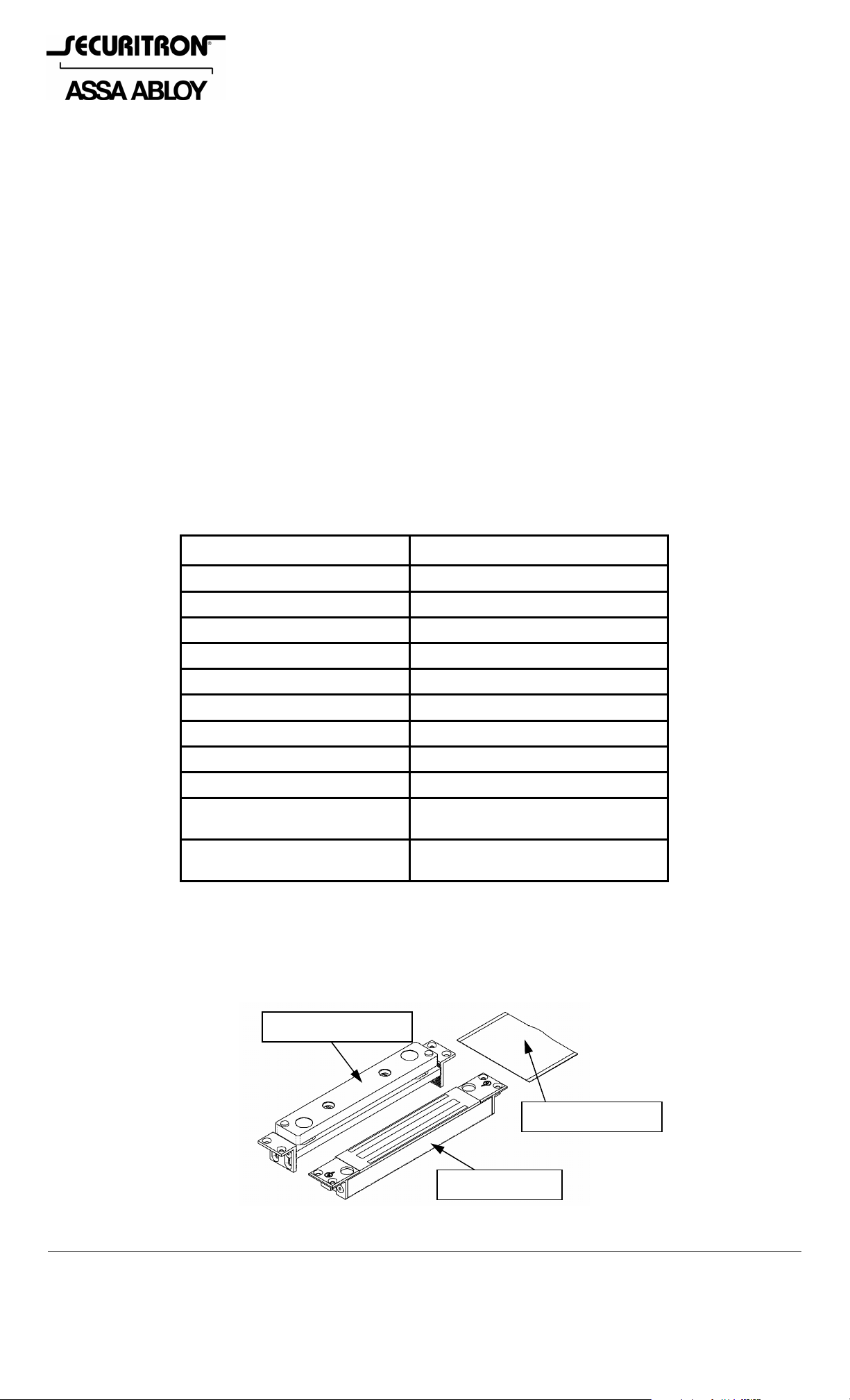
Upon unpacking this product, an inventory should be made to ensure that all the required
components and hardware have been included. Along with these instructions and the
installation template, each product should include the following items:
Strike Assembly
Hardware Pack
Magnalock
Figure 1 - SAM Series Magnalock
© Copyright, 2012, all rights reserved PN# 500-10440
Page 1 Rev. F, 02/12
Page 2
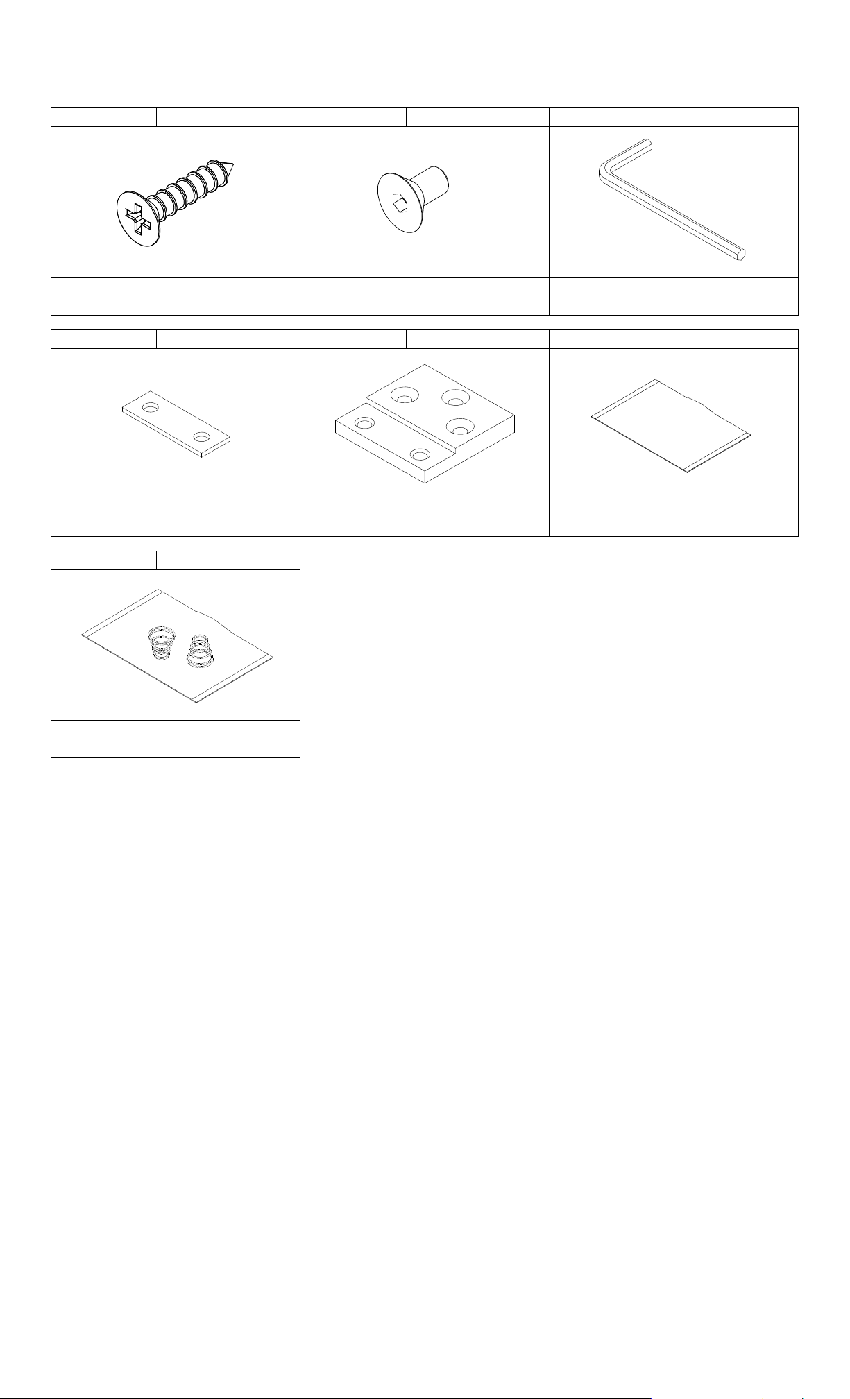
3.1 HARDWARE
10X 20X 1X
Hex Wrench
1/8”
Phillips Flat Head
#10 X 3/4” Type “A”
Socket Flat Head
10-32 X 3/8”
8X 4X 1X
Shim Plate Flush Mount Bracket
Thread Locking Compound
Pack
1X
Floor Install Replacement
Spring Pack (2 Springs)
4 RECOMMENDED TOOLS
Router or Saber Saw 1/8” Hex Key (Allen Wrench) - included
Hammer Measuring Instrument (Ruler/Tape Measure)
Chisel Masking Tape
Center Punch Fish Tape or Lead Wire
Power Drill Wire Strippers/Cutter
9/64”, 13/64” & 5/16” Drill Bits Crimp Wire Connectors
3/8” Diameter X 82° Countersink Bit Crimp Tool
Phillips and Standard Screwdrivers Multimeter
5 INSTALLATION INSTRUCTIONS
5.1 Pre-Installation Survey
It is recommended that an initial on sight survey be performed. A method of mounting should
be determined and an installation plan should be reviewed as follows:
Physical strength of mounting areas should be strong enough to meet or exceed the holding
force of the required Magnalock.
Placement of the Magnalock wiring and protection from potential damage due to intruders or
vandals external attack should be considered during the survey.
Accessibility should be considered for prevention of any potential safety hazard.
PN# 500-10440
Page 2 Rev. F, 02/12
Page 3
The door and frame areas additionally need to be examined for mortising capabilities, sufficie nt
size and should be free of any internal obstructions. The top-of-door installation is
recommended as the most suitable location for protection from impact attacks.
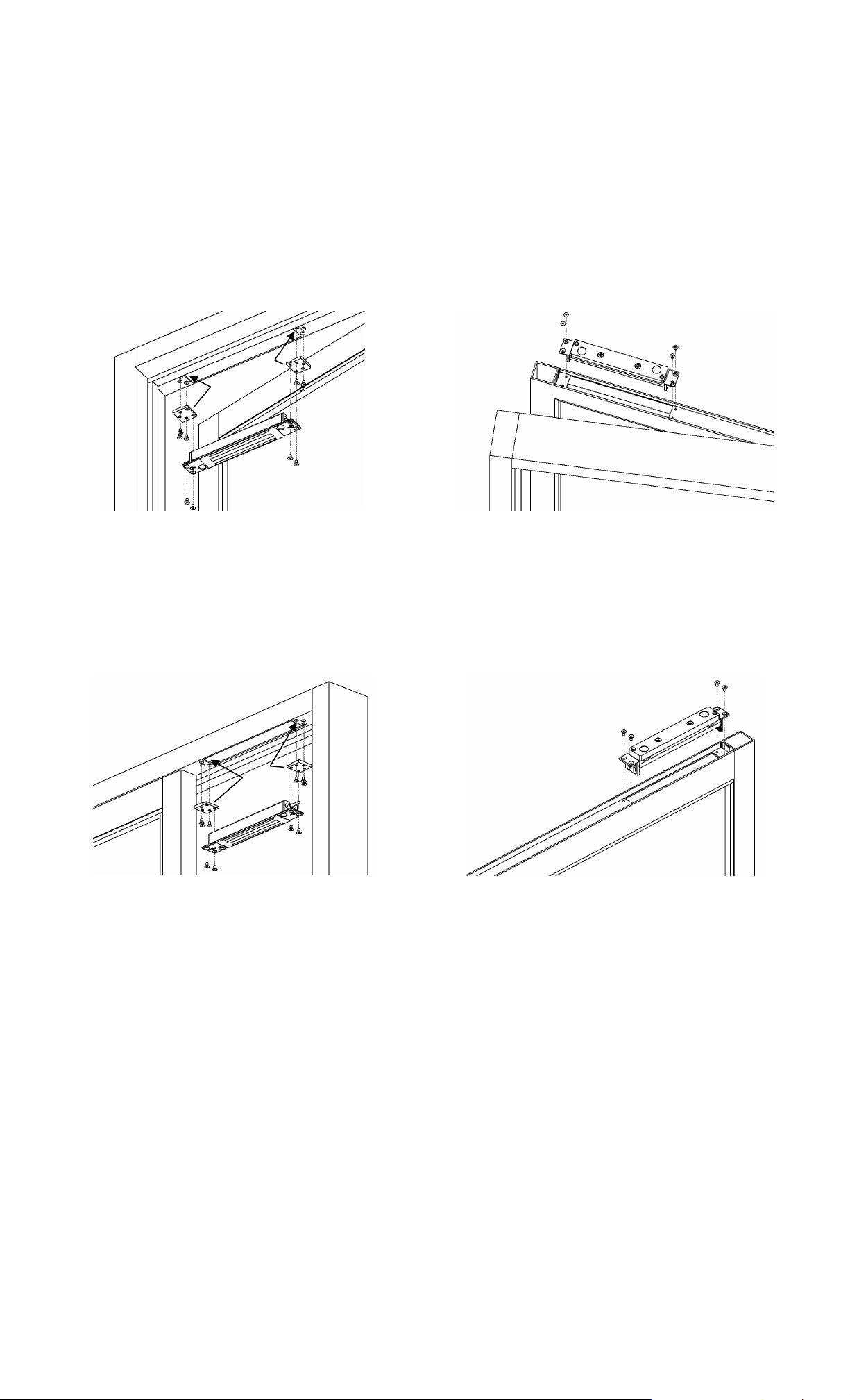
5.2 Swinging Door
The illustrations in Figure 2 demonstrate a SAM installed in a swinging door. This is a common
configuration where the Magnalock is recessed into the door frame header near the corner
opposite the hinge side and the strike assembly is flush mounted into the top edge of the door.
The Magnalock may be mounted horizontally or vertically depending on the installation required.
The flush mount brackets shown are inserted into hollow metal door frame to provide a recessed
installation.
Magnalock mounted in door frame Strike mounted in edge of door
Figure 2 - Swinging door configuration
5.3 Sliding Door
The illustrations in Figure 3 demonstrate a SAM installed in a sliding door. The Magnalock
mounts recessed into the door frame header and the strike assembly is mounted into the top
edge of the sliding door.
Magnalock mounted in door frame Strike mounted in edge of door
Figure 3 - Sliding door mounting configuration
5.4 Frame and Door Preparation
5.4.1 Frame Preparation
Select a mounting location for the Magnalock and st rike assembly as mentioned in Section 5.1.
The following general guideline should be used for consideration during the installation review:
Read and follow the directions on the template provided which includes drilling and
mounting instructions.
An approximated 2” [51mm] clearance distance should be allowed between the Magnalock
(mounting bracket) and the inside corner of the door frame. This will provide adequate
access for the mounting locations and for drilling and tool access.
ALWAYS CHECK THE STRIKE MOUNTING AREA IN THE EDGE OF THE DOOR FOR
OBSTACLES WHEN DETERMINING WHERE TO LOCATE THE MAGNALOCK. MAKE
CERTAIN THAT THE STRIKE MOUNTING AREA DOES NOT HAVE ANY OBSTRUCTIONS
(I.E. DOOR ADJUSTMENT SCREWS OR DOOR CLOSER OPERATORS) THAT MIGHT
HINDER INSTALLATION - BEFORE CUTTING OR DRILLING ANY HOLES.
PN# 500-10440
Page 3 Rev. F, 02/12
Page 4

Locate and mark the desired lateral centerline p osition for the Magnal ock/strike assembly on t he
face of the door. Using this door mark as reference, mark the same later al center location of the
Magnalock onto the door frame.
Setting the depth center position of the Magnalock is more critical because there is not a lot
of free depth in the door frame or door to accommodate any centering error. To locate the
centerline in the door frame:
o For a one-way swing door
: Make sure the door is closed completely and measure the
distance between the face of the door and the frame stop (usually about 1/8”). O pen the
door and measure the thickness of the door. Divide the thickness of th e door in half (this
will be the center of door) and add the distance measured between the door and stop.
Measure the total distance out from the face of the stop and mark the centerline for the
Magnalock.
o For a bi-directional swing door
: Ensure the door is in the centered at-rest position. (A
door closer may require adjustment). Using a pencil, trace the inside and outside edge s
of the door onto the frame. Measure half the distance between these two marked door
silhouette lines and mark the centerline for the Magnalock.
Using the Magnalock mounting information in Section 5.5 and the lock template provided,
align the appropriate template into position on the frame and mark the mortise cutout area.
Using a router or saber saw, or chisel (for wood) cut out the area for the Magnalock
mounting. Insert the Magnalock into the frame and mark the bracket locations for the
mounting holes.
Using the drill size information on the template and a power drill, bore the holes required.
5.4.2 Door Preparation
Locate the previously marked lateral centerline po sition for the strike assembly on the fa ce of
the door.
Open the door and measure the total depth distance (thickness) of the door. Divide this
distance in half to locate the depth centerline of the strike assembly.
Using the strike assembly mounting information in Section 5.6 and the strike template
provided, center the template into position on the door and mark the mortise cutout area.
Using a router, saber saw or chisel (for wood) cut out the area for the strike assembly
mounting. Insert the strike assembly into the door and mark the bracket locations for the
mounting holes.
Using the drill size information on the template and a power drill, bore the holes required.
IF MOUNTING THE STRIKE AT THE BOTTOM OF THE DOOR (FLOOR MOUNT) IS CHOSEN,
THE TWO (2) IDLE PLATE SPRINGS IN THE STRIKE ASSEMBLY NEED TO BE REPLACED
WITH THE ALTERNATE SET OF IDLE SPRINGS PROVIDED IN THE HARDWARE PACK.
5.5 Mounting the Magnalock
The desired cable exit location should be determined prior to installing the Magnalock. The
Magnalock is symmetrical which allows the cable exit from either end into the doo r frame. There
are many different techniques for mounting the Magnalock depending on the type or style of
doors and frames. The following sections describe installation methods for use on hollow
aluminum, steel and wood type doors and frames.
5.5.1 Hollow Metal Door Frames
Prepare the door frame in accordance with Section 5.4.1.
Place the Magnalock into the cutout area to ensure proper fit. As necessary, perform any filing
or cutting necessary to ensure the mortised fit. Ensure all necessary holes required to moun t
the Magnalock and flush mount brackets into place as indicated on the template have been
provided. Install the Magnalock using a hex wrench, the listed mounting screws and the flush
mount brackets as shown in Figures 4 and 5 below.
The adaptation to variation in frame material thicknesses can be obtained by flipping the
orientation of the flush mount brackets. Shim plates are also provided which may be used in
conjunction with the flush mount brackets to create the desired exposed height of the Magnalock
and/or to compensate for the various material thicknesses of do or frame s.
PN# 500-10440
Page 4 Rev. F, 02/12
Page 5
It is recommended that the Magnalock face protrude approximately 1/16” [1.6mm]
beyond the surface of the frame. Both Figures 4 and 5 show a shim plate between the lock
mounting bracket and the flush mount bracket in order to raise the Magnalock above the fra me
surface.
Flush Mount Bracket
(Note Orientation)
Figure 4 - Flush mount bracket mounting (thin wall frame)
Flush Mount Bracket
(Note Orientation)
Figure 5 - Flush mount bracket mounting (thick wall frame)
APPLY THE PROVIDED THREAD LOCKING COMPOUND TO ALL MOUNTING SCREW
THREADS.
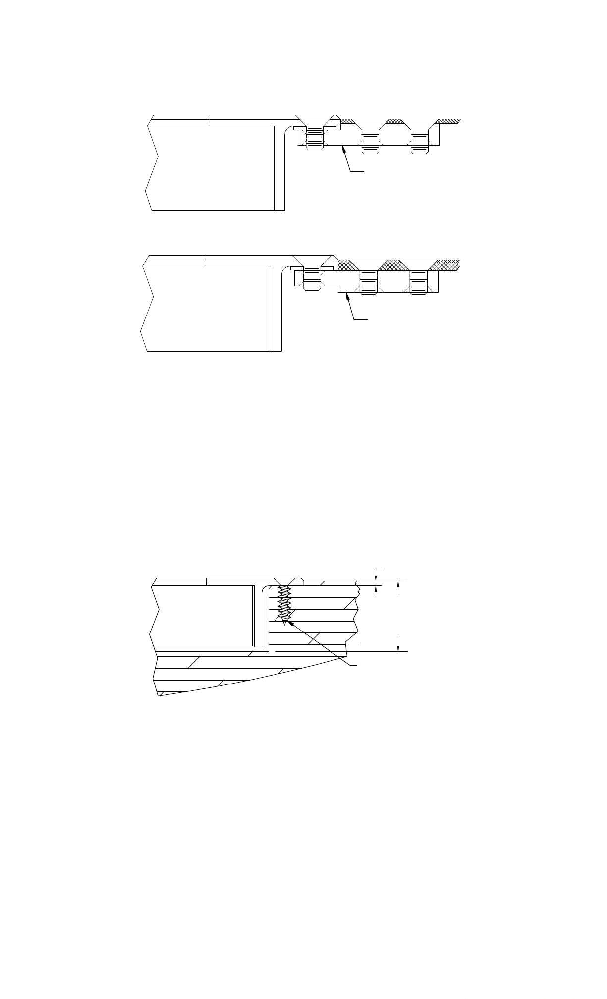
5.5.2 Solid Wood Door Frames
Prepare the door frame in accordance with Section 5.4.1.
Place the Magnalock into the cutout area to ensure proper fit. As necessary, perform any filing
or chiseling necessary to ensure the mortised fit. Ensure all necessary holes required to mou nt
the Magnalock into place as indicated on the template have been provided. The depth of the
mortise cut out is important for proper fit. The minimum depth of the cutout is no ted in Figure
6 below and includes enough distance for the required recess depth of 1/16” [1.6mm] for the
mounting brackets. Install the Magnalock using the wood mounting screws as shown in Figure
6.
1/16" [1.6]
Mortise Depth
1-1/8"
[28.6]
#10 x 3/4" Phillips
Flat Head Type "A"
Figure 6 - Wood frame lock bracket mounting
5.6 Mounting the Strike Assembly
The strike plate mounting method varies with the type of door being used. The included
template provides preparation and installation information for the various types of doors. The
following sections describe the door type and installation procedures.
The strike bracket assembly has been designed with adjustment features which are intended to
help accurately install and adjust the strike assembly for proper operation. The two L-shaped
end brackets and the idle bracket of the assembly are serrated to provide a secure locking
adjustment of the height of the strike in the door edge. The end brackets have obround slots to
limit the adjustment travel and to support the structure of the assembly. By loosening the
screws at each end, the brackets can be adjusted to the desired mounting height.
PN# 500-10440
Page 5 Rev. F, 02/12
Page 6

The serrations on the brackets are .050” [1.3mm] apart which matches the screw thread pitch
distance that mounts the strike. This feature will be explained during the final adjustment in
Section 5.7. These end brackets may also be inverted to provide for deeper mounting
configurations. See Figure 8 and Figure 9 for adjustable ranges and mounting methods.
THE POSITION OF THE CENTERLINE OF THE STRIKE ASSEMBLY IS CRITICALLY
RELATED TO THE CENTERLINE OF THE MAGNALOCK LOCATION.
5.6.1 Hollow Metal Door (Flush Top)
Prepare the door in accordance with Section 5.4.2.
Mounting the strike assembly into a door with flush outside surfaces u tilizes the same methods
as mounting the Magnalock into a hollow metal type frame. Figure 7 below shows a typical
installation in a flush type aluminum door. In this process the flush mount brackets are u sed to
suspend the strike assembly into the door. Make the necessary adjustme nts to the end bra cket s
of the strike assembly to set the initial strike height in the door installation. The flush mount
brackets may be installed in either direction (see Figures 4 and 5) to set the appropriate flush
mounting condition, and the provided shim plates may also be used to assist in further
adjustment of the installation. Use a hex wrench and the provided mounting screws to complete
the installation.
Strike
Flush Mount Bracket
(Note Orientation)
Idle Bracket
End Bracket
Figure 7 - Hollow frame strike assembly mounting
APPLY THE PROVIDED THREAD LOCKING COMPOUND TO ALL MOUNTING SCREW
THREADS.
5.6.2 Hollow Aluminum Door (Shallow Recess Top)
Prepare the door in accordance with Section 5.4.2.
If the door has a shallow recess within the range indicated in Figure 8, a cut out area will be
required to insert the strike assembly. Cut out the strike mou nting area using a router or saber
saw. The templates provided specify the dimensions of the cutouts and the locations of the
holes for proper mounting. In this process the flush mount brackets are not required becau se
the strike can mount suspended in the door using the door edge only. Make the necessary
adjustments to the end brackets to set the initial strike height in the door installation. If
necessary, the provided shim plates may be used under the bracket mounts to create the proper
mount distance.
1/8" [3.2] to 1-3/8" [34.9]
Strike
Cross Section
Idle Bracket
End Bracket
#10 x 3/ 4" Phillips
Flat Head Type "A"
of
Door Recess
Figure 8 - Shallow recess door strike mounting
PN# 500-10440
Page 6 Rev. F, 02/12
Page 7

5.6.3 Hollow Aluminum Door (Deep Recess Top)
For mounting of the strike assembly into doors with deep recessed su rfaces as shown in Figure
9, no cutout for the strike assembly is required. Remove and invert the end brackets to increase
the height range of the strike bracket assembly. The strike will mount staged from the bottom
of the door recess by using the frame only. Make the necessary adjustments to the end
brackets to set the strike height in the door installation.
Strike
Idle Bracket
End Bracket
10-32 x 3/8"
1-1/2" [38.1] to
2" [50.8]
Flat Head Screw
Into Tapped Hole
Cross Section
of
Door Recess
Figure 9 - Deep recess door strike mounting
APPLY THE PROVIDED THREAD LOCKING COMPOUND TO ALL MOUNTING SCREW
THREADS.
5.6.4 Hard Core Wood Door
Prepare the door in accordance with Section 5.4.2.
For mounting into hard core (solid) wood doors the strike assembly may be mounted with or
without the end brackets attached. The door cutout requires a mortise area for the strike base
assembly with sizes that are dependent on whether the end brackets are used or not (see
template). The depth requirements are illustrated in Figures 10 and 11. If the installation
does not require use of the end brackets (as shown in Figure 10), the installer must be
accurate on the depth of the cutout. (If the mortised cutout is too shallow it will not allow
enough room for the strike to be adjusted down any lower and the door operation may be
hindered. If the cutout is too deep, shimming may be necessary to adjust the idle bracket
height in the installation). When the end brackets are used, the cutout area require s a minim um
depth (shown in Figure 11) and because of the adjustability in the end brackets, cutting the
recess too deep will not affect the installation.
Strike
Mortise Depth
1"
[25.4]
Idle Bracket
#10 x 3/4" Phillips
Flat Head Type "A"
Figure 10 - Wood door strike mounting without brackets
PN# 500-10440
Page 7 Rev. F, 02/12
Page 8

5.6.5 Soft Core Wood Door
Use of the end brackets is recommended when installing the strike assembly on soft core wood
style doors because a “pocketed” soft core door is not as strong in supporting the lateral forces
applied to the strike assembly. Use of the end brackets will provide a much more sound and
secure anchoring platform for the installation. Refer to Section 5.6 fo r use and adjustment of
the end brackets. Figure 11 illustrates the dimensional requirements of the cutout necessary
for installation into wood doors using the strike end brackets.
1/8"
Strike
Mortise Depth
1-7/16"
[36.5]
Idle Bracket
#10 x 3/4" Phillips
Flat Head Type "A"
End Bracket
Figure 11 - Wood door strike mounting with brackets
5.6.6 Magnalock/Strike Installation for “B” and “D” SAM Locks
IMPORTANT!
PLEASE READ AND APPLY THIS INFORMATION WHEN ALIGNING/INSTALLING THE
LOCK AND STRIKE. THE ALIGNMENT TOLERANCES INDICATED FOR THE SAM LOCK
MODEL ARE CONSIDERED CRITICAL FOR THE PROPER OPERATION OF BOTH THE
MAGNETIC BOND SENSING (MBS) AND DOOR POSITION SENSING (DPS) SYSTEMS!
SENSOR RANGES (PHYSICAL POSITIONING):
The BondSTAT “B” and DPS “D” Magnalock “Secure Zone” sensing range for the SAM lock
model is as follows:
Secure Sensor Indication Range
(Dimensions from Center)
Model "X" (+/-) "Y" (+/-)
SAM 5/32" [4.0] 5/64" [2.0]
Table A
Figure 12
(The Figure 12 illustration is a visual reference to the sensing range outlined in Table A).
***SPECIAL NOTE FOR SAM “D” MAGNALOCK (DOUBLE TRIGGER NOTIFICATION)***
The Magnalock mounting direction in slider doors should be considered critical for
proper operation.
For SAM “D” units, the Magnalock position should be installed with the cable furthest from the
door closing face as shown in Figure 13. This allows proper sensing of the door operation. If
the Magnalock direction is reversed the reed switch will be triggered by both actuator magnets in
the face of the strike assembly. Double triggering may cause inaccurate signals to access/alarm
control devices attached.
PN# 500-10440
Page 8 Rev. F, 02/12
Page 9

Slider Door Installation
Figure 13
5.7 Strike Assembly Final Adjustments
5.7.1 Strike Level Adjustment (De-energized)
De-energized adjustment of the strike height is important for proper door/lock operations. The
example in Figure 14 illustrates the Magnalock with the proper adjustment. Without power
applied to the Magnalock, both of the (conical) interference buttons should just clear the lock
brackets. Check this by opening and closing the door. To adjust the clearance to be closer, turn
each of the strike adjustment (shoulder) screws (located in the center of the strike) counterclockwise 1/4 turn, one at a time and recheck the clearances. (Both screws do not have to be
adjusted the same amount of turns). The adjustm ents should be made independently so that
the strike level is uniform to the door frame and Magnalock installation. The strike screws are
allowed up to two (2) full turns of adjustment each. If the adjustment required is two (2)
full turns or greater, then tighten the screws clockwise back to the down position, loosen the end
bracket screws and adjust the end brackets the amount of notches necessary to enable the final
adjustments. Repeat adjustments as necessary until a properly functioning gap setting is
achieved.
THE INITIAL SETTING OF THE STRIKE ADJUSTMENT (SHOULDER) SCREWS SHOULD BE
NO MORE THAN TWO (2) TURNS OUT. THIS WILL ALLOW A LARGER ADJUSTMENT
RANGE TO ACCOMMODATE POTENTIAL FUTURE DOOR SAG.
THE CONICAL INTERFERENCE BUTTONS ON THE STRIKE PLATE SHOULD JUST CLEAR
THE LOCK BRACKET SURFACES TO INSURE THE CORRECT GAP.
.100 [2.5]
to
.125 [3.2]
Clearance
Figure 14 - Magnalock and strike assembly (side view)
5.7.2 Strike Level Adjustment Testing (Energized)
Energized adjustment testing of the strike height is important for proper door/lock operations.
This adjustment should be performed after the de-energized adjustment, illustrated in Section
5.7.1. With the door closed and the Magnalock de-energized, apply power to the Magnalock.
The strike should be pulled up against the Magnalock face. De-energize the Magnalock and the
strike should return to the previously adjusted height. This function should be tested several
times to insure that the strike level adjustment is correct. If the strike is not pulled up to the
face of the Magnalock, the strike is to far away from the Magnalock. Make small 1/4 turn
adjustments to the strike screws until the correct level and clearances are obtain ed for proper
function.
A second test should be performed with the door starting from the opened position. Apply
power to the Magnalock and then close the door under normal operations. The strike should be
PN# 500-10440
Page 9 Rev. F, 02/12
Page 10

attracted to the Magnalock, but the strike and the interference buttons should pass completely
into the locking position to secure the door. Test this operation several times to ensure
consistent operation of the Magnalock/strike installation.
WHEN THE MAGNALOCK IS ENERGIZED FOR A CONTINUOUS DUTY MODE, THE
ADJUSTMENTS MADE MAKE IT A POSITIVE LOCKING MODE FOR CONTROLLED ACCESS.
IF THE MAGNALOCK IS SET FOR CONTINUOUS DUTY, THE EXIT REQUEST ALLOWS THE
STRIKE TO DROP AWAY AND CLEAR FOR SMOOTH EGRESS. WHEN THE MAGNALOCK
BECOMES ENERGIZED, WHILE THE DOOR IS STILL IN THE OPENED POSITION, THE
DOOR CLOSING AND LOCKING FEATURES WILL STILL FUNCTION, WHEN THE DOOR
CLOSES, THE STRIKE REALIGNS BACK TO THE LOCKING POSITION TO SECURE. THERE
SHOULD BE NO INTERFERENCES THAT PREVENT THE DOOR FROM CLOSING OR
BECOMING SECURE.
5.8 Mounting on Motorized Bi-Parting Doors
Bi-Parting Motorized Doors are commonly found on the perimeters of large retail stores or
supermarkets. One (1) or two (2) doors electrically slide open for entering or exiting purposes.
They are typically activated by either a motion detector or pressure sensitive type mat. The
doors are also designed to allow emergency egress in the event of a fire . The emergency eg ress
is allowed by a fail safe condition to the door. This is used to turn off any lock peripherals or
motor devices that operate or secure the door. The door is designed with a secondary
directional movement to swing open which is called “breakaway”.
Doors that are set to remain locked, after the establishment has closed, have the possibly of
accessing the breakaway feature by prying the door open. Installing a SAM Magnalock in the
door for access control will help resist the possibility to enter through the breakaway feature.
6 ELECTRICAL INSTALLATION
6.1 General Characteristics
The Magnalock is a low current load device using specialized internal circuitry. The normal
characteristic of an inductive load, such as inductive kick-back, is not present. See Section 2
for more information.
6.2 Electrical Standards
DC voltage, full-wave rectified, must be provided for proper operation of the Magnalock. The red
wire receives +12VDC or +24VDC, and the black wire, 0 Volts (negative). If the Magnalock is
connected with reverse polarity, it will not operate. The SAM Series Magnalocks are auto
sensing dual voltage locks. The Magnalock circuit design will automatically select the proper
operational conditions for the applied voltage.
6.3 Poor Release Characteristics
The SAM Magnalock is designed with quick release operation. Wiring errors may cause a
Magnalock to release slowly. Figure 15 illustrates a parallel installation of a resistive load
(correct). Figure 16 illustrates a parallel reverse diode (incorrect).
Figure 15 Figure 16
6.4 Sensor Ranges (ELECTRICAL)
The SAM “B” version monitoring system is also voltage sensitive. The specified voltage ranges
must be properly applied. Refer to Section 2 for the recommended operating voltage ranges.
PN# 500-10440
Page 10 Rev. F, 02/12
Page 11

6.5 Electrical Wiring
The following diagrams, Figures 17, 18, 19 and 20 represent the proper electrical wiring
connections required for SAM Magnalock Standard, and for SAM BondSTAT “B”, DPS “D” and
“BD” versions.
DC
POWER
SUPPLY
120
VAC
INPUT
*12/24
VDC
OUTPUT
DC
POWER
SUPPLY
120
VAC
INPUT
12/24
VDC
OUTPUT
+
_
+
_
ACCES S
SAM ST ANDARD
CONTROL
DEVICE
NC
C
NO
Figure 17
2-WIRE MAGNALOCK
SAM SERIES "B"
ACCES S
CONTROL
BondSTAT VERSION
5-WIRE MAGNALOCK
DEVICE
NC
C
NO NC
REF.
LOCK
LOCK
STATUS
STATUS
VERSION
RED
+
BLK
RED
_
+
WHT
GRN
ORG
BLK
C
NO
_
DC
POWER
SUPPLY
120
VAC
INPUT
12/24
VDC
OUTPUT
DC
POW ER
SUPPLY
120
VAC
INPUT
12/24
VDC
OUTPUT
+
_
+
_
Figure 18
ACCESS
CONTROL
DEVICE
NC
C
NO
REF.
DOOR
STATUS
Figure 19
ACCESS
CONTROL
DEVICE
NC
C
NO
REF.
LOCK
STATUS
REF.
DOOR
STATUS
SAM SERIES "D"
DPS VERSION
5-WIRE MAGNALOCK
RED
+
YEL
C
BLU
NC
BRN
NO
_
BLK
SAM SERIES "BD"
BondSTAT/DP S V E RS ION
8-WIRE MAGNAL O C K
RED
+
WHT
C
GRN
NC
ORG
NO
YEL
C
BLU
NC
BRN
NO
_
BLK
Figure 20
PN# 500-10440
Page 11 Rev. F, 02/12
Page 12

6.6 BondSTAT Sensor status wiring description
The green and white wires supply electrical connection when the lock is ON and secure.
The orange and white wires supply electrical connection when the lock is OFF or unsecure.
6.7 DPS – Door Position Sensor status wiring description
The blue and yellow wires supply electrical connection when the door condition is closed.
The brown and yellow wires supply electrical connection when the door condition is open.
6.8 Double Door Status Wiring - BondSTAT
When two Magnalocks are used for double door installation the BondSTAT contacts should be
wired in series for proper reporting. Connect the green wire of one lock to the white wire of the
other as shown below in Figure 21.
Figure 21
6.9 Double Door Status Wiring - DPS
When two Magnalocks are used for double door installation the DPS contacts should be wired in
series for proper reporting. Connect the blue wire of one lock to the yellow wire of the other as
shown below in Figure 22.
Figure 22
6.10 Emergency Release
Magnalocks are often wired into a system for quick release in case of emergency. Manual
switching or automatic triggering from a fire alarm system is practical. It is the user's
responsibility to correctly hookup the Magnalock according to the instructions. It is
recommended to use a switch or relay to perform break of power. Securitron power supplies
have terminals for the interconnection of such emergency release switches.
THE END USER AND INSTALLER ARE LIABLE FOR ALL FIRE AND BUILDING CODE
COMPLIANCE.
7 SPECIALIZED MOUNTING BRACKETS AND STRIKES
SMLS – Surface Mount Lock Housing is a brushed stainless steel bracket/housing for
surface mounting the SAM Magnalock in installations where mortising the lock is not possible.
SMSS – Surface Mount Strike Housing is a brushed stainless steel bracket/housing for
surface mounting the SAM strike assembly in installations where mortising the strike is not
possible.
SWB – SAM Wood Bracket is a U-shaped (wrap style) reinforcement bracket used when
mortising the SAM strike assembly into the edge of a 1-3/4” thick wooden door. The bracket
is available in three different architectural finishes (US3, US10B and US26D).
SAMN - Narrow Strike – The SAMN is a standard SAM Magnalock with a narrow strike
assembly provided for installations where the standard width strike will not fit. (The narrow
strike is not available in the “B” or “D” versions of the SAM series Magnalock).
PN# 500-10440
Page 12 Rev. F, 02/12
Page 13

8 MAGNALOCK MAINTENANCE
8.1 Visual Inspection
Check the strike assembly for proper gap, suspension and free movement. Tighten strike
adjustment screws as required.
Check for build-up of debris on the Magnalock and strike armature. Clean as required.
Check for rust on the Magnalock and strike assembly. Clean as required.
8.2 Cleaning Methods
Cleaning once a year is recommended.
Clean every six months where minor rusting occurs.
Clean every three months if rust conditions are severe.
Use a plastic dishwashing scrub pad to aid in the removal of rust.
DO NOT USE PETROLEUM BASED PRODUCTS FOR CLEANING
DO NOT USE STEEL WOOL BASED SCRUB PAD OR SANDPAPER
8.2.1 Indoor Applications
Apply rubbing alcohol onto a clean cloth and thoroughly wipe down the Magnalock and
strike plate armature.
8.2.2 Outdoor Applications
Apply a silicone based cleaner/lubricant onto a clean cloth and thoroughly wipe down
Magnalock and strike plate armature.
Example: Super Lube® Aerosol with SYNCOLON® (PTFE)
Part No.: 31040 ~ 6oz. / 31110 ~ 11 oz. / 32015 ~ 14 oz.
Phone: (631) 567-5300 / Website: www.super-lube.com
APPENDIX A
Troubleshooting
Problem Lock Does Not Generate a Magnetic Field Points of Reference
Check for specified voltage at Magnalock
Section 2
Solution
Check for specified current draw at Magnalock Section 2
Problem Reduced Holding Force Points of Reference
Check DC power source is Full-Wave Rectified
(Half-wave Rectifier or AC Power unacceptable)
Check for specified voltage at Magnalock
Section 2
Section 6.2
Solution
Check for specified current draw at Magnalock Section 2
Check strike mounting for proper installation Sections 5.6-5.7
Check the Magnalock and strike for obstructions
and that contact surfaces are properly cleaned
Section 8
Problem BondSTAT Does Not Report Secure Points of Reference
Check for specified voltage at Magnalock
Section 2
Check for specified current draw at Magnalock Section 2
Solution
PN# 500-10440
Page 13 Rev. F, 02/12
Check strike mounting for proper alignment and
pivoting for proper closure to Magnalock
Check the Magnalock and strike for obstructions
and that contact surfaces are properly cleaned
Table A / Section 5.6.6
Section 8
Page 14

Problem DPS Does Not Report Door Status Points of Reference
Check strike mounting for proper alignment Table A / Section 5.6.6
Solution
Check for proper door closure
Check for proper voltage/current on switch
Check resettable protection device
Section 8.1
Section 2
Section 1
Problem The Magnalock Does Not Release Points of Reference
Make sure no voltage is present at Magnalock Section 2
Solution
Make sure the Magnalock is not drawing current Section 2
Check if the strike is sticky and hard to release
Check the Magnalock and strike for obstructions
and that contact surfaces are properly cleaned
Section 8
Section 8
Problem The Magnalock is Dirty or Rusty Points of Reference
Solution
Problem
Solution
Improper cleaning – Maintenance Equipment Section 8
Electronic Noise Interference with
Access Control System
Check for voltage from Magnalock to door frame.
There should be no voltage present.
Points of Reference
Section 2
IF PROBLEMS PERSIST CALL SECURITRON TOLL FREE
(800) MAG-LOCK
(800) 624-5625
Appendix B
Wire Gauge Factoring
1.1 Remote Power Supply
The Magnalock requires adequate voltage and current for proper operation.
Resistance is created by the length and gauge (size) of the wire being used.
An accurate estimated distance from the power supply to the opening is crucial.
For superior operation the correct size gauge wire must be used.
The devices used operate the best with the least amount of resistance on the source.
Using the correct gauge wires protects against large voltage and current (load) losses.
The gauge is determined by the wire distance, voltage and current of all devices.
1.2 Determining Wire Gauge
Follow Example A (12VDC system) and Example B (24VDC system) below.
Use Tables 1 and Table 2 to choose the corr ect wire gauge for the application.
1.2.1 Example A: (12VDC system)
Devices Used Amps (12VDC)
SAM Magnalock 0.320
DK-26 Access 0.160
XMS Motion Detector 0.050
EEB2 Timer 0.025
Total Current (0.555A) Rounded Up =
0.600A
Using Table 1 (12VDC) Find: - Current Draw .600 Amps
- Wire Distance 200 Feet [61m] (One-Way)
Solution: 18 Gauge is indicated for proper installation
PN# 500-10440
Page 14 Rev. F, 02/12
Page 15

1.2.2 Example B: (24VDC system)
Total Current (0.440A) Rounded Up =
Devices Used 24VDC Amps
SAM Magnalock 0.320
DK-11 Access 0.070
XDT-24 Delay 0.050
0.600A
Using Table 2 (24VDC) Find: - Current Draw .600 Amps
- Wire Distance 1000 Feet [305m] (One-Way)
Solution: 14 Gauge is indicated for proper installation
TO SOLVE: INTERSECT ROW (Total Current Draw) and INTERSECTING COLUMN (OneWay Wire Distance).
1.00A
.800A
C
U
.600A
R
R
E
.400A
N
T
.300A
.200A
12VDC
20
Gauge
22
Gauge
22
Gauge
22
Gauge
24
Gauge
24
Gauge
50’
[15m]
18
Gauge
18
Gauge
20
Gauge
22
Gauge
22
Gauge
22
Gauge
100’
[30m]
16
Gauge
18
Gauge
18
Gauge
20
Gauge
22
Gauge
22
Gauge
150’
[46m]
14
Gauge
16
Gauge
18
Gauge
18
Gauge
20
Gauge
22
Gauge
200’
[61m]
14
Gauge
14
Gauge
16
Gauge
18
Gauge
18
Gauge
20
Gauge
300’
[91m]
WIRE DISTANCE
12
Gauge
12
Gauge
14
Gauge
16
Gauge
18
Gauge
18
Gauge
400’
[122m]
10
Gauge
10
Gauge
14
Gauge
14
Gauge
16
Gauge
18
Gauge
500’
[152m]
10
Gauge 8 Gauge
10
Gauge 8 Gauge
12
Gauge
14
Gauge
14
Gauge
16
Gauge
750’
[229m]
10
Gauge
12
Gauge
14
Gauge
14
Gauge
1000’
[305m]
Table 1
1.00A
.800A
C
U
.600A
R
R
E
.400A
N
T
.300A
.200A
24VDC
22
Gauge
22
Gauge
24
Gauge
24
Gauge
24
Gauge
24
Gauge
50’
[15m]
20
Gauge
22
Gauge
22
Gauge
22
Gauge
24
Gauge
24
Gauge
100’
[30m]
20
Gauge
20
Gauge
22
Gauge
22
Gauge
22
Gauge
24
Gauge
150’
[46m]
18
Gauge
18
Gauge
20
Gauge
22
Gauge
22
Gauge
22
Gauge
200’
[61m]
16
Gauge
18
Gauge
18
Gauge
20
Gauge
22
Gauge
22
Gauge
300’
[91m]
WIRE DISTANCE
14
Gauge
16
Gauge
18
Gauge
18
Gauge
20
Gauge
22
Gauge
400’
[122m]
14
Gauge
14
Gauge
16
Gauge
18
Gauge
20
Gauge
20
Gauge
500’
[152m]
12
Gauge
14
Gauge
14
Gauge
16
Gauge
18
Gauge
20
Gauge
750’
[229m]
10
Gauge
12
Gauge
14
Gauge
14
Gauge
16
Gauge
18
Gauge
1000’
[305m]
Table 2
The Wire Distance indicated on the table above represents a 2-wire “One-Way” length from
the power supply source to entryway installation area.
The Gauge values specified on the table above represent a 2-wire “Round Trip” length from
the power supply source to entryway installation and returning back to the power supply
source.
IMPORTANT
THE 200’ [61m] WIRE RUN IN EACH TABLE FACTORS A 400’ [122m] ROUND TRIP
PN# 500-10440
Page 15 Rev. F, 02/12
Page 16

MAGNACARE LIFETIME REPLACEMENT WARRANTY
For warranty information visit www.securitron.com/en/site/securitron/About/MagnaCare-Warranty/
PATENTS
The Securitron Shear Aligning Magnalock is listed under U.S. patent #4,516,114 and
6,007,119.
Additional patents pending
PN# 500-10440
Page 16 Rev. F, 02/12
 Loading...