

Page 1

Securitron Magnalock Corp. www.securitron.com ASSA ABLOY, the global leader
Tel 800.624.5625 techsupport@securitron.com
in door opening solutions
SECURITRON MODEL PSM-12, PSM-24 POWER SUPPLY MONITOR
INSTALLATION AND OPERATING INSTRUCTIONS
1. DESCRIPTION
The Power Supply Monitor is a microprocessor controlled product which provides comprehensive
monitoring of a strictly regulated battery charging power supply. Separate versions are
available for 12 and 24 volt power supplies. The PSM performs a series of continuous and
periodic tests to detect possible problems with the power supply and battery pack. Failure of
any of these tests is reported by both local and remote signals. The PSM can therefore be used
as a stand alone monitor or it may be connected to an alarm system.
The PSM also reports any time the batteries are switched into the load circuit (from a local
power outage for instance). Finally the PSM will disconnect the batteries from the load when
their output falls below 88% of nominal. This is to preserve them from going into deep
discharge and to prevent the load receiving a low voltage that may cause operational problems.
2. APPLICABLE POWER SUPPLIES
The Power Supply Monitor is qualified for use with Securitron power supplies models: BPS-12-3,
BPS-12-4.5, BPS-12-6, BPS-12-9, BPS-12-15, BPS-24-2, BPS-24-3, BPS-24-4, BPS-24-6, and
BPS-24-10. It is not qualified for use with Securitron 1 Amp power supplies. There are
two reasons for this. First, the PSM requires power to ope rate: 200 mA @ 24 volts; 250 mA @
12 volts and therefore reduces the total capacity of the supply. It is hard to justify its use with a
small capacity supply. Second, Securitron 1 Amp supplies are not "strictly" regulated. This
simply means that their output voltage varies somewhat with the load. While this does not
cause operational problems (the variation is low), it would create con stant "false alarms" on the
part of the PSM, which expects strict regulation.
The issue of using the PSM with non Securitron power supplies is uncertain. The
general type of supply that can be used with the PSM is one that will operate the load with or
without batteries. When batteries are added, they are continuously trickle charged and
automatically take over the load (generally through a diode), only when the normal DC output o f
the power supply drops out. The specific supply, however, may have some operating
characteristic that makes it unsuitable for use with the PSM. Check with the factory.
3. TESTS
3.1 VOLTAGE LEVEL TESTS
To properly charge the batteries, the power supply should out put a precise voltage: 13.65 volts
for a 12V battery pack and 27.3 volts for a 24V battery pack. If the voltage is too low, the
batteries will never get fully charged. If it is too high, they will heat up and suffer reduced lifespan. The PSM continually monitors this voltage and will report a low or h igh failure. If the h igh
or low condition in output voltage is short lived, it will be ignored. A good example of this is a
momentary drop in voltage caused by a large load being switched in. The out of range voltage
condition must be maintained for 30 seconds for the PSM to report it.
Once the high or low condition is maintained for 30 seconds, the PSM will report it in latching
fashion. A "high" or "low" yellow LED will illuminate on the PS M enclosure cover, the Sonalert
will emit a pulsing output and SPDT "trouble" contacts will switch for remote signaling. This
signal will be maintained even if the out of range voltage condition has corrected itself. The
power supply should still be examined. To reset the unit, voltage should be adjusted to the
correct level and then the reset toggle on the enclosure cover should be momentarily depressed.
Power supply adjustment should be done as follows. With the PSM connected to the power
supply as explained in Section 5, identify the voltage adjustment potentiometer on the power
supply. Slowly turn the pot so as to increase the voltage until the green "power normal" L ED
just turns off. Then slowly turn the pot in the opposite direction (the green LED will immediately
come back on) until the green LED turns off because of low voltage. Center the pot between
these two points of movement. If you have a voltmeter to confirm your result, voltage should
be at roughly 13.65V for a 12 volt unit and 27.3V for a 24 volt unit.
© Copyright, 2011, all rights reserved PN# 500-16200
Page 1 Rev. D, 08/11
Page 2

3.2 BATTERY TEST
The only way to reliably test a battery pack is to disconnect it from its trickle charge circuit,
apply a load to it and measure the performance of the battery pack. A perfect test would
duplicate the actual load and conduct the test for the amount of time that the pack could be
expected to operate the load. Such a complete test would not only verify that the battery pack
was prepared to operate the load for some time, but would verify the full rated capacity of the
pack.
In a working installation, such a test is obviously impossible. It would not only ta ke too long but
would risk leaving the batteries in a discharged state at the moment that a real power failure
occurs. It is important therefore to understand what Securitron's PSM battery test signifies. The
battery pack is automatically disconnected and a heavy test load of two Amps is applied. The
test duration is three minutes every eight hours and during this time, the battery voltage is
monitored. If it does not fall below 11.5V (for a 12 volt pack) or 23V (for a 24 volt pack), the
test is considered passed and no alarm signal is sent. Such a test indicate s that the batteries
are properly connected and charging and that they have no major defect such as an internal
shorted or open cell. The end user is assured that in an actual power failure the batteries wi ll
operate the working load for some time, but it is possible that they may not deliver their full
rated capacity. Battery performance varies with temperature and degrades over time.
Batteries must be replaced every five years minimum. It is vital that the presence of the
Power Supply Monitor not lead to a false sense that as long as the Monitor does not
signal an alarm, the batteries are in perfect condition.
Another concern in automatic battery testing is that during the test, the batteries are
disconnected from the trickle charge voltage source. It is possible that an actual power failure
could occur during the test and, if so, the test must be immediately terminated so that the
batteries can return to their primary function of backing up the working load. In Securitron's
model PSM, this is automatically accomplished by detecting an actual DC output power failure
and terminating any concurrent battery test as well as preventing any test from beginning
during the period of power failure.
Battery test reporting is as follows. A yellow LED o n the enclosure cover illuminates during th e
test duration (three minutes every eight hours). If the test fails, it terminates at the failure
point and a red "loading failed" LED comes on. The Sonalert sounds a continuous tone and the
"trouble" relay contacts switch. Note that this auto matic test will not be conducted if the PSM is
in alarm from another condition such as voltage out of range. To reset the unit, the reset togg le
on the enclosure cover should be momentarily depressed. Be sure to replace the battery
pack upon any battery test failure.
It is possible to trigger a battery test manually at any time the PSM is in normal condtion.
Simply press the momentary "load test" toggle on the enclosure cover.
4. "ON BATTERY" REPORTING AND SYSTEM DISCONNECT
The PSM also reports any power failure when the batteries have switched in and are operating
the load. A yellow "on battery" LED will illuminate showing that the batteries are a ctive and the
"on battery" SPDT remote contacts will switch. The Sonalert will not sound from this effect as
this is not a test failure condition, but after 30 seconds, a low DC failure will also be detected so
the Sonalert will begin to pulse and the "trouble" contacts will switch. Note that the term "power
failure" does not only refer to a line voltage failure. The power supply could have an internal
failure which has either terminated or lowered its D C output. Any of these conditio ns will lea d to
the batteries taking over the load and the PSM will report that fact regardless of the cause.
Once the batteries have been switched in, they will only be able to operate the load for a defined
period of time depending on their capacity and on the current being drawn by the load. The
PSM's signal that the batteries have been switched in, can therefore be considered a type of
advance warning. If DC power is not restored, the installation will go down. The end user
should have an idea of how much reaction time he has by knowing the installation load current
and the battery pack size.
Under battery operation, the load will receive nearly the correct voltage until the batteries are
close to the end of their capacity. At that point, battery voltage will begin to fal l off rapidly. Th e
PSM will detect the point at which battery voltage has dropped to 88% nominal (10.5V or 21V)
PN# 500-16200
Page 2 Rev. D, 08/11
Page 3
and automatically take the batteries off the load. At that point the "on battery" contacts will
T
switch back to normal condition and a red "system disconnect" LED will illuminate on the panel
enclosure cover. The system disconnect condition will also terminate the low DC signals (LE D,
pulsing Sonalert and "trouble" contacts) as the PSM no longer has the power to operate these
functions. The PSM itself is dependent on the battery power which has now been terminated.
There are two reasons for this system disconnect. Once the batteries are close to the end of
their capacity, there is no reason to throw them into deep discharge as this is so mewhat harmful
to the batteries. The more significant reason is that security equipment designed to run at 12 or
24 volts will begin to fail in hard to predict ways as the opera tin g voltage drops belo w 10.5 or 21
volts. Operating an installation at this sort of indeterminate voltage can even create a
safety hazard. For example, consider a perimeter security installation that employs magne tic
locks and control devices for the locks such as timers or pow ered exit devices. With declining
system voltage, a situation could arise where the locks were still largely holding but the control
devices were failing because of low voltage. This would render the doors unusable. It is
therefore safer to abruptly cut power when voltage falls into an indeterminate range.
When the PSM has disconnected the batteries, they still supply a small amount of power
sufficient to illuminate the red LED. There are also some leakage currents such that a batte ry
pack in system disconnect will continu e to be drained at roughly 50 mA. While quite small, thi s
current will eventually deep discharge the batteries, so the user should always try to restore
normal charging as soon as possible.
System disconnect is accomplished by a set of 10 Amp rated contacts on terminals F1 and F2 in
the PSM which will open in system disconnect. These terminals are wired in series with the load
(see Section 5.2).
5. WIRING
5.1 BASIC WIRING WITH SECURITRON POWER SUPPLY
"Basic" wiring permits the PSM to perform all of its monitoring functions but does not include
system disconnect. This is because system disconnect wiring may be done in two different ways
depending on whether there is a second system disconnect switch. See Section 5.2.
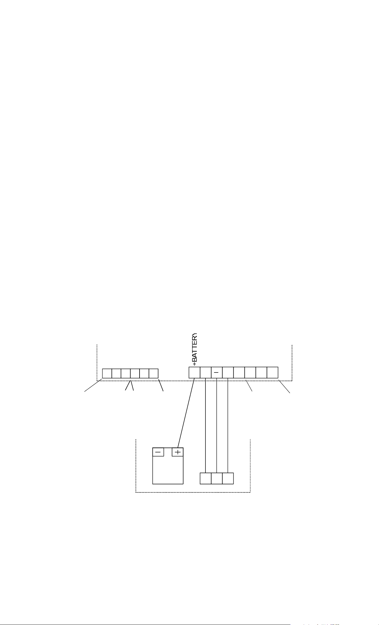
FIG. 1: PSM BASIC WIRING WITH SECURITRON POWER SUPPLY
PSM
C
NC NC NOC
C
ON B ATTERY
SPDT
OUTPUT
NO
TROUBLE
SPDT
OUTP UT
BATTERY
PACK
B+
B+
R1
F1 F2
F1
NC
SECURITRON POWER SUPPLY
For basic wiring, refer to Figure 1. This shows all of the PSM terminals and the basic four wire
hookup to any of the Securitron power supplies called out in Section 2 of this ma nual. Be sure
that the voltage of the PSM (12 or 24) matches the voltage of the power supply.
NO
SYSTEM
DISCONNEC
SPDT
OUTP UT
(NORMALLY
ENERGIZED)
PN# 500-16200
Page 3 Rev. D, 08/11
Page 4

Terminal F1 of the power supply connects to terminal F1 of th e PSM. This terminal supplies +V
L
in constant fashion. It serves to power the PSM and also provide s the test point for monitoring
the power supply's output voltage. Terminal R1 of the power supply (or any of the "R"
terminals), connects to terminal "-" of the PSM to provide a negative DC return. Terminal B+ of
the power supply is the charge output that normally connects directly to the Battery "+"
terminal. It must no longer connect to the Battery "+" terminal but instead should
connect to terminal B+ in the PSM. The Battery "+" terminal from the power supply
battery pack must connect only to terminal "Battery +" in the PSM. By breaking the
former +DC connection from the power supply to its battery, the PSM is a ble to take the batter y
off its charge terminal in order to conduct its periodic battery testing. Naturally, the battery
negative terminal remains connected to terminal "B-" of the power supply. This is not shown as
it does not represent a change. All power supply to load connections are unchanged by
the addition of the PSM to the installation.
There are three sets of SPDT contacts which are furnished dry on the PSM and which are shown
in the drawing. These report "trouble", "on battery" operation and "system disconnect". They
may be used as the customer desires to provide remote monitoring. For example, they may be
connected to an alarm system. Note that the "trouble" and "on battery" contacts are normally
deenergized. They will switch to report a problem. The system disconnect contacts are
however normally energized. They drop out to report system disconnect because the PSM
has no power at that point and would not be able to keep the associated relay energized. So,
for example, if you wanted a closed loop to open to indicate syste m disconnect, you would use
the C and NO terminals as these are closed (energized) in the normal condition.
5.2 SYSTEM DISCONNECT WIRING
As has been discussed earlier in Section 4, the PSM will automatically take the batteries off the
load when their voltage has declined below 88% of nominal. This wi ll fully depower the load as
the batteries are the only source of power when they have discharged to that point. It is
generally best that this disconnection occurs as electronic systems should not be operated at
indeterminate voltages well under their specified requirements. Note that it is also possible that
the power supply has experienced a defect which has caused it to output a dangerously low
voltage. Since system disconnect separates the load from both the power supply output and the
batteries, it will deal with any problem that produces a low, indeterminate voltag e .
FIG. 2: ADDITIONAL CONNECTIONS FOR SYSTEM DISCONNECT
PSM
F1 F2
F1 F2
POWER SUPPLY
SYSTEM DISCONNECT
WIRING WITH NO OTHER
SYSTEM RELEASE
PSM
F1 F2
F1 F2
POWER SUPPLY
SYSTEM DISCONNECT
WIRING WITH FIRE ALARM
SYSTEM RELEASE
FIRE ALARM RE
C NC
Refer to Figure 2. Terminal F1 in the PSM receives +V power directly from the power supply.
Terminal F2 in the PSM connects to F1 in the PSM via an internal 10 Amp relay contact which is
closed in the normal condition. So in the normal conditi on, terminal F2 in the PSM can output
+V. In system disconnect, the connection between terminals F1 and F2 in the PSM opens, so
there is no voltage on F2.
Securitron power supplies have constant +V on their te rminal F1 and their terminal F2 conn ects
to the load through the power supply circuit breakers. Therefore, for any Securitron power
supply to drive its load, terminals F1 and F2 in the power supply must be connected. This can
be done as is shown in the left side of Figure 2. This connection allows the PSM to release the
load in system disconnect. However, the installation may require additional release contacts. In
a magnetic lock installation, this is generally fire alarm auxiliary latching NC contacts. The right
PN# 500-16200
Page 4 Rev. D, 08/11
Page 5

side of Figure 2 shows how to connect the PSM system dis connect conta cts in serie s with the fire
.
alarm contacts. Any number of release switching means can be connected in this way.
6. SYSTEM TEST
It is particularly vital to test the PSM after wiring is complete. Most equipment tests
itself in a sense by working after installation. When the PS M and its associated power supply are
both working, nothing happens. No signals are received from the PSM. Therefore the only way
to assure that the PSM is functioning correctly is to test it. We recommend that these set up
tests be performed periodically with the frequency of testing being determined by the
importance of the installation.
VOLTAGE LEVEL TEST
Start with the voltage level properly adjusted so that the green "power
normal" LED is on and the voltage adjustment pot on the power supply is
RESET
centered in between the two points where the green LED just goes out. If
you have a voltmeter, adjust power supply voltage higher by one volt. If you
don't have a voltmeter, just make a quarter turn on the pot towards higher
voltage. In 30 seconds, the "power high" LED should come on, the Sonalert
should pulse and the trouble contacts should switch. Lower the voltage so
that the green LED comes on again and then momentarily press the reset
POWER NORMAL
POWER LOW
POWER HIGH
toggle. The alarm signals should clear. Repeat this test by reducing the
voltage in the same manner as you increased it earlier, with the result being
LOAD TEST
illumination of the "power low" LED and the associated Sonalert/contact
outputs. Return the supply to correct (green LED on) voltage by carefully
LOADING FAILED
following the procedure set out in the last paragraph of Section 3.1.
ON BATTERY
ON BATTERY TEST
Remove line voltage from the power supply. The yellow, "on battery" LED
SYSTEM DISCON
should come on immediately and the "on battery" contacts should switch.
Within 30 seconds, the "power low" yellow LED shou ld come on, the Sonalert
should pulse and the "trouble" contacts should switch. Reconnect line
LOAD TEST
voltage, make sure you see the green "power normal" LED and momentarily
depress the reset toggle to clear these conditions.
BATTERY LOAD TEST
With the PSM in normal condition, momentarily depress the "load test" toggle. The yellow "load
test" LED should come on. This test will automatically run for three minutes. At the end of two
minutes, disconnect line voltage from the supply. The te st should immediately terminate (the
"load test" LED will go out) and the batteries will switch into the load. R econnect line voltage.
This shows that the test function works and that the test will automatically terminate if the
batteries are suddenly required to operate the load (owing to a line voltage failure for instance).
If the load test failed (red "loading failed" LED illuminated) before the two minutes were up on a
new installation, it may be that the batteries became discharged during storage and shipping.
The test should be repeated after the batteries have been fully charged by the power supply.
The time this will take depends on the size of the pack, but it could take as long as a day.
Assuming the first part of the battery load test was successful, repeat it by pressing the load te st
toggle a second time (with all power supply/PSM connections in the normal state). To simulate
a bad battery pack, remove one of the battery clip leads tem porarily. The red "loading failed"
LED should illuminate, the Sonalert should sound a steady tone and the "trouble" contacts
should switch. Reconnecting the battery clip lead should not end the alarm s ignals. Press the
reset to toggle to clear this condition.
SYSTEM DISCONNECT TEST
To make the PSM go into system disconnect, you have to present it with a voltage lower than
10.5V (for a 12V PSM) or 21 volts (for a 24V PSM). To accomplish this test for a 24V PSM,
proceed as follows. The 24 volt battery pack will be made up of 12 volt batteries in series.
Isolate a single 12V battery and connect it to the PSM and po wer supply as if it was the normal
battery pack. This connection will eventually damage the battery but will do no harm for a
PN# 500-16200
Page 5 Rev. D, 08/11
Page 6

minute or two. Once the battery is connected in, disconnect line voltage. The PSM should
illuminate its red "system disconnect" LED and disconnect the load by opening PSM terminals F1
and F2. There should be no output from the "P" terminals in the power supply. The system
disconnect relay contacts on the PSM should be in the deenergized alarm state. Reconnect line
voltage and the PSM should return to normal. Restore the 24 volt battery pack.
With a 12 volt PSM and power supply, it is more difficult to test system disconnect. If you have
a 6V battery, you can follow the procedure described above, but if you don't it's not easy to
produce the required low voltage except by disconnecting line voltage and waiting long enou gh
for the batteries to decline to system disconnect level. If you have a multiple battery pack,
using only one battery will make this time as short as possible. If you have no time to perfor m
that test, perform the test show in the previous paragraph b y disconnecting line voltage with no
battery pack connected at all. This will at least show that the load releases properly.
If any of the tests fail, consult the factory. Do not put the system into operation.
7. SIGNALING SUMMARY
For reference, we are providing a summary of the meaning of different output signals from the
PSM.
PULSING SONALERT
Indicates a high or low voltage alarm that has persisted for 30 seconds. Can arise from
misadjustment of the power supply, a defect in the power supply or an interruption of line
voltage. Always accompanied by an output from the "trouble" contacts. This is a latching signal
that will continue even if the out of range voltage condition has corrected itself. Voltage must be
adjusted following the procedure explained in the final paragraph of Section 3.1 and then the
reset toggle must be pressed to clear the condition.
STEADY SONALERT
Indicates that one of the three minute battery load tests has failed. Accompanied by the red
"loading failed" LED and an output from the "trouble" contacts. The batterie s can no longer be
considered reliable so the pack must be replaced. This latching condition is cleared by the reset
toggle.
"TROUBLE" CONTACTS
This signal is intended to summon an authorized person in a situation where the Sonalert wou ld
not be heard. Indicates voltage out of range or the failure of a battery load test. Consultin g the
LED's determine which fault has caused the "trouble" contacts to switch. This latching condition
is cleared by the reset toggle after the underlying problem has been corrected.
"ON BATTERY" CONTACTS
Signals that, for any reason, the power supply is no longer operating the load and the batteries
have taken over. The load will only operate for the period the batteries can provide backup.
Accompanied by the yellow "on battery" LED. 30 seconds later, the PSM will report a power low
fault and the pulsing Sonlalert will begin to sound together with its asso ciated "power low" LED
and the "trouble" contacts.
"SYSTEM DISCONNECT” CONTACTS
Signals that the voltage operating the load has fallen below 10.5V (for a 12V system) or 21V (for
a 24V system) and power has therefore been removed from the load to avoid operation at an
indeterminate voltage. Proper voltage must be restored to recover from this condition.
8. CALCULATING BACKUP TIME FOR A BATTERY PACK
This is another reference section which explains h ow to calculate the approximate backup time
that a given installation can expect from a given battery pack. Knowing this figure allows the
end user to understand how much time he has to react to a power failure.
It should first be understood that the calculation is independent of voltage. It doesn't matter
whether the system is 12 or 24 volts. To make the calculation, you need only know the current
drawn by the load (expressed in Amps) and the capacity of the battery pack (in Amp-Hours).
PN# 500-16200
Page 6 Rev. D, 08/11
Page 7

To get the load current, it is usually easiest to work from product specification s. For instance, if
you know that the installation consists of eight Securitron Magnalocks w hich are shown in their
catalog sheets as drawing 125 mA each, you would know that the eight together should draw
one Amp. The alternate method of getting the load current is to measure it with an ammeter.
The meter is connected in series with the output of the power supply.
A complicating factor occurs when the load is not constant. Many installations consist of a
number of devices that are randomly turned on and off at different times. In this case you hav e
to make an estimate of duty cycle. For example a load might draw 1/2 Amps all the time as a
base condition, but 25% of the time it would go up to 2 Amps. To roughly analyze such a
situation, you would add the 1/2 Amp baseline to 25% of the surge (increase over baseline).
25% of the 1 1/2 Amp surge is 3/8 Amps so the total average load is 7/8 Amps. It is never
possible to get an exact value of the load but a good estimate is all that's required when making
sure you have enough backup. This is because you should always err on the side of extra
backup by specifying an oversized battery pack.
Once you have the load current, you need the battery pack capacity. This is derived by simply
noting the capacity in Amp-Hours called out on the battery. If there is more than one batter y
connected in parallel (such as two 12 V batteries in a 12 volt system) you add the capa cities.
When two batteries are connected in series (which always happens in a 24 volt system), the
capacity is unchanged. In other words, two 4 Amp Hour 12 volt batteries conne cted in series
to back up a 24 volt power supply yield 4 Amp Hours at 24 volts. In 24 volt systems, you'll
often find parallel/series battery packs. For example a 24 volt battery pack could consist of
eight 4 Amp Hour 12 volt individual batteries. First, the eight batteries are connected in pairs in
series to make four 24 volt, 4 Amp Hour packs. Then these four packs are all connected in
parallel to boost the Amp Hour rating at 24 volts to 16 Amp Hours.
Once you have the total average load and the battery pack capacity, you divide the former into
the latter to get the base backup time. For example, a load drawing 1 1/2 Amps, backed up by
a 16 Amp Hour pack would yield a base backup time of 10.7 Hours. The base backup time has
to then be derated to yield the actual backup time.
A number of factors decrease battery capacity. They include: improper charging, low
temperature, age and the discharge rate. Taking these in order, you can ignore improper
charging since you're using a Power Supply Monitor that effectively guarantees proper charging.
If the batteries are not in a room temperature environment, their capacity will b e reduced. For
example, a 20 degree F drop in temperature will reduce total capacity by about 10% . Generally,
this is not a factor as the batteries are typically housed within a power supply enclosure which
maintains an elevated temperature. Age will not be a factor so long as the batteries are
replaced at least every five years. The discharge rate, however, always needs to be considered.
Actual backup time will equal base (calculated) time only when the dischar ge rate is 20 hours or
more. In other words, if base backup time is calculated at 25 hour s, you can take that figure as
being representative of the actual backup time you will get. When the base backup time is
shorter than 20 hours, you have to derate to determine your actual backup time. This is simply
because batteries do not perform as well when they are being discharged rapidly. The chart
below shows the derating factor for different base backup times.
BASE BACKUP TIME % CAPACITY YIELD
20 Hours 100%
10 Hours 90%
4 Hours 80%
2 Hours 70%
1 Hour 60%
30 Minutes 45%
15 Minutes 30%
The chart makes it clear that the shorter the base backup time, the more the battery pack will
lose capacity so as to produce an even shorter actual backup time. For example, consider a 4
Amp Hour battery backup up for a 1 Amp load. The base backup time is four hours but you
have to derate to 80% so you'll only get 3 hours,12 minutes. If the load was 4 Amps, your base
backup time would be one hour. This figure would have to be derated to 60% or 36 minutes.
PN# 500-16200
Page 7 Rev. D, 08/11
Page 8

The final lesson of this Section on calculating battery pack performance is make sure you build in
a margin for error. Batteries are a minor cost in any installation.
9. MAGNACARE LIFETIME REPLACEMENT WARRANTY
For warranty information visit: www.securitron.com/en/site/securitron/About/MagnaCare-Warranty/
PN# 500-16200
Page 8 Rev. D, 08/11
 Loading...