

Page 1
PDB-8C8R and 8F8R
Access Control Distribution Board
PDB-8F8R/8C8R Power Distribution for Access Control with Fire Interface module
Controls and Distributes Power with 8 Control Relays with an EOL Fire trigger Interface
Power Interface for Access Control, CCTV, Fire, and general low voltage system control
Features:
• 8 Heavy duty Relays with individual Inputs and Status LED’s
• Each Relay Input can be Activated from Low Current Open Collector, Normally
Closed or Normally Open Switch
• EOL End of Line Resistor Fire Interface Master Trigger de-energizes all Output
Relays that are Enabled
• Universal 12 – 28VDC power input(Nominal 12-24VDC)
• 8C8R is Class 2 Power Limited
• Class 1 wiring required for 8F8R unless powered by a UL 294 or 603 or ULC
S318 or ULC S533 listed power supply with class 2 output. There shall be a
min of ¼ separation between power limited and non-power-limited circuits.
• Available with Fuses or PTC Circuit Breakers
Each Output may be Individually Configured for:
o Fire Trigger (FT) Enabled or (FTD) Disabled
o N/O or N/C Option Configures the Relay Switched Output
• Each Output 1-8 has a protected, continuous Output and a Relay controlled Output
• Control Power and Main Lock Power may be Isolated (Separate Power Supplies) at Users Option
Note: Dual/separate power source configuration has not been evaluated by UL and cannot be configured for UL Listed products
Description / Instructions
The PDB-8F8R is a versatile, compact way to distribute and control
power for Access Control Systems with Fire Alarm Interface. The
PDB-8F8R is an 8 position power distribution board with individual
Relays with input (IN) control for each output (OUT). An EOL
resistor trigger input (TRIG), will force all output relays to deenergize that are selected (FT). In a typical installation, the TRIG
would be connected to a Fire Alarm panel via a set of contacts.
When the Fire Alarm trips, all enabled relays would be forced to be
de-energized to unlock electric doors, shut down air systems, and
or return elevators to ground floor.
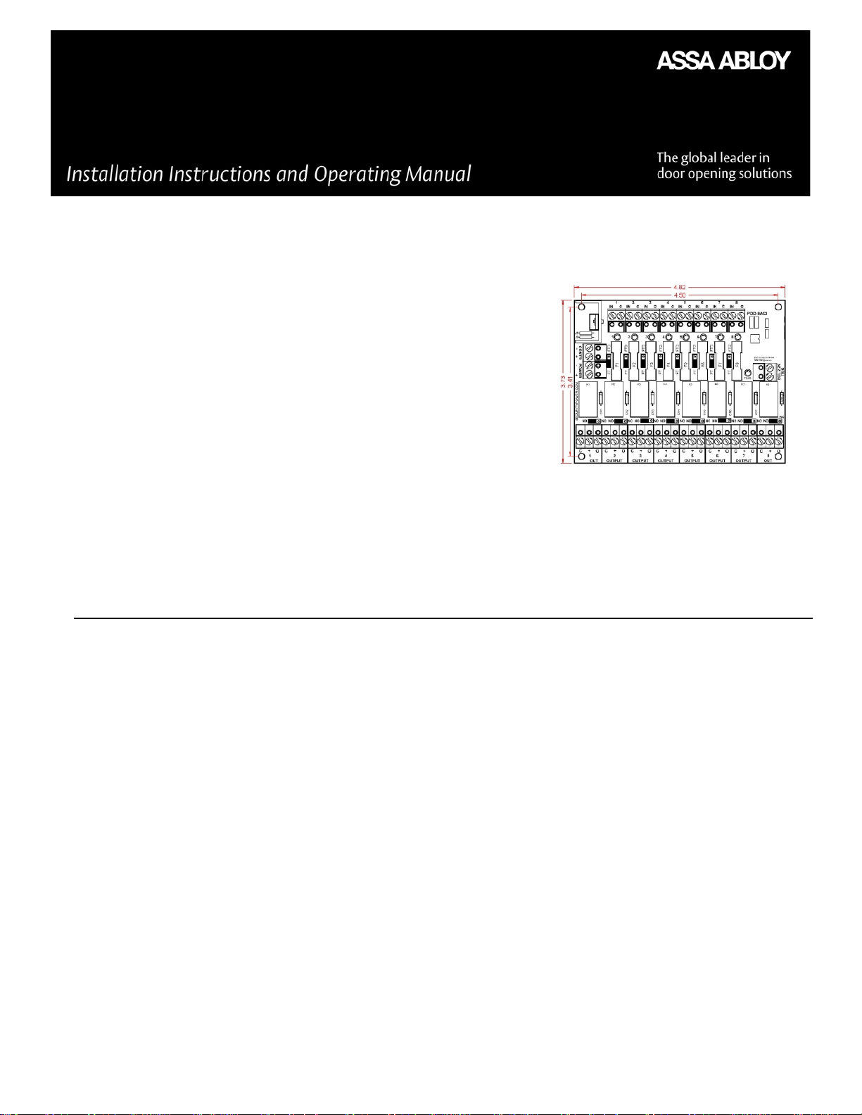
Input / Output Terminals, Jumpers and LED
Details and Specifications
Control Power (- CONTR +) Two position un-pluggable terminal
block is used to power the coils of the relays. The control voltage
must be between 12 and 28 VDC. Each relay energized will draw
20ma of current. By default, Control Power and Main Power are
connected together with jumpers J1 & J2 so no connection would
be made here unless you were using Dual/separate power as
described below. Note Dual/separate power source configuration
has not been evaluated by UL and cannot be configured for UL
Listed products.
Main Power (- POWER +) Two position un-pluggable terminal
block provides the power to the outputs to be distributed and
power to Control through J1 & J2. In a normal application, the
Power must be between 12-28VDC and would be connected here.
Dual/Separate Power J1 & J2 Jumpers Note Dual/separate power
source configuration has not been evaluated by UL and cannot be
configured for UL Listed products. J1 Connects (-) Power to (-)
Control, J2 Connects (+) Power to (+) Control. By default J1 & J2 are
connected together. When J1 & J2 are cut, you must supply 12 to
24VDC to Control power See Dual/Separate Power application
figure below.
Inputs (1-8 IN C) Eight, two position un-pluggable terminal blocks.
When IN & C are shorted together, the like number output relay will
energize. Each relay can also be energized by an open collector that
is common to the control power, sinking 20ma for each input. Each
of the C’s (common) are connected to control negative power.
Input LED’s (1-8) Whenever an input is active (relay energized) the
associated input red LED will illuminate.
FDT/FT (1-8) Jumpers - These are three pin headers adjacent to
each fuse with a shunt with handle that shorts the center pin to
FTD or FT.
FTD = Fire Trigger Disabled - When selected, the Trigger will
not effect that output.
1
500-33045_2
Page 2

Normally no connection is made here. Note: Dual/separate power source configuration has not been evaluated by UL and cannot be
configured for UL Listed products.
Note: The unit shall be installed in accordance with the National Electrical Code, ANSI/NFPA 70; Canadian Electrical Code, or any other
applicable codes.
FT = Fire Trigger – When selected Triggering will force that
Input Relay to De-Energize.
Dry/Wet Option (1-8 Fuse Models 8F8R) Through a Fuse, the
(+ Power) is connected to the swing arm of each Relay to distribute
power to its output. Removing the Fuse, removes the power from
the relay. The (+) now becomes the Common Swing Arm and the
“O” is the N/O or N/C contact as selected with jumper.
Outputs (1-8 OUTPUT C, +, O) Eight, Three position un-pluggable
terminal blocks. “C” is Power Common and is connected to
(- power). “+” is connected to fused (+ power) and the relay swing
arm. “O” is the relay switched output as selected with N/O or N/C
selector jumper.
Specifications
Control (- CONTR +) 12–24VDC @ 37mA
Main Power (-power+) 12-28VDC (12-24 VDC Nominal)
Note: Must cut J1 & J2 when not using 12-24VDC power See Dual/Separate power source configuration
Fused/Wet Outputs (11.2-28V DC operation):
Max. Output Current 2A variants 2A per port / Total 16A
Max. Output Current 1A variants 1A per port; Total 8A
Total Power Supply draw would be equal to the total current of the outputs load plus the module draw of 37mA
Dry Outputs (Models 8F8R only) 3A, 30VDC; 3A, 250VAC Resistive Load.
Terminal blocks un-pluggable
Note: Wires should be properly sized based on output load
PTC Rating Outputs 1-8 2.5A for 2A variants, 1.1A for 1A variants
Glass Fuse Rating Output 1-8 2A,250VAC ; 1A,250VAC
2A Replacement: Littelfuse part number 0217002.HXP. 1Amp replacement: Littelfuse part number 0217001.HXP
Caution: For continued protection against risk of fire, replace only with fuse of the same type and having the same electrical ratings.
The fused outputs of the PDB-8F8R are power limited only when connected a UL Listed power-limited power supply
Output Relays 1-8 Dry Contacts are not to exceed 100VA
Trigger Input 2.2K EOL
Operating Temperature 0o to +49oC
Mounting Holes (4) 3.4” x 4.5”
Module Size: 4.82”w x 3.84h x 1.4”d
UL Listings
UL 294 Access Control System Unit
UL 603 Power supplies for Use with Burglar-Alarm Systems
ULC S318 Power supplies for Burglar Alarm Systems
ULC S533 Standard for Egress Door Securing and Releasing Devices
Output Relay Contacts Selector (1-8 NC/NO) Jumpers These 3 pin
headers with shunt selectors are located just above each output
which selects whether the N/C or N/O contacts are connected to
the “O” switched output terminal. With N/C selected, output would
be normally ON, or connected to swing arm. With N/O selected,
output would turn ON, or close when input is activated.
Fire Alarm Interface Trigger (2.2K EOL TRIG) Two position unpluggable terminal block. This input must see the 2.2K ohm EOL
(End Of Line) resistor to be in the normal condition. The EOL is to
be placed in a Listed fire alarm panel. See Fig 1 illustrating that
shorting or opening the EOL will cause the PDB-8F8R to trigger.
TRIG LED (TRIG) Green LED normally ON. Whenever the Trigger is
active the LED will be OFF.
5mm spacing 14–22 awg
Line Security Level I
Endurance Test Level IV
Standby Power Level I
Attack Test Level I
Note: For UL compliance unit shall be installed in a suitable enclosure that is listed to UL 603 or UL 294 or ULC-S318 or ULC-S533.
Note: All interconnected devices must be UL Listed.
2
Page 3

PDB-8F8R Typical Applications
Single Power Source Application Fig 1
500-33045_2
3
 Loading...