

Securitron PDB-8C1R, PDB-8F1R Installation Instructions
PDB-8C1R and 8F1R
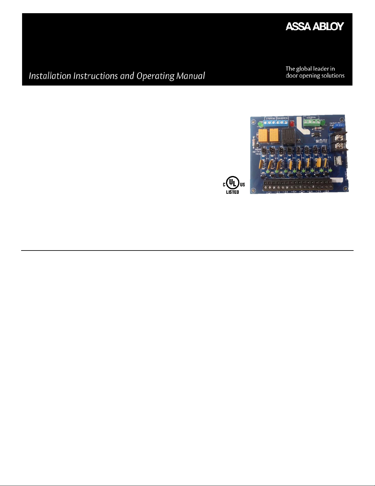
Power Distribution Boards
Distributed Power Control Interface for Fire, Access, HVAC, Elevator, and Security
Features:
• 8 Power Limited Outputs with Auto-Resetting
• Circuit Breakers for model 8C1R
• Each Output is Individually Selectable to
Turn On, Turn Off, or always ON when Triggered
• Outputs can be triggered with:
1. Voltage or Reverse polarity (optically isolated)
2. N/O or N/C switch with supervised EOL
• Form C Contacts (TRIGGERED) and Red LED (TRG)
Indicate Trigger Status
• Form C Contacts (TROUBLE) and Green LED (TRB)
Indicate:
1. One of the output circuit breakers is tripped
• Main Fuse Blown or no power on input
• Operates with 12-28VDC; Nominal 12-24VDC
• Each Output pair has a Removable Terminal Block
• Each Output has a Green Status LED
• Main Power has Green Status LED
• Main Power Pull and Fuse
• Lifetime Warranty
• UL Listed Sub Assembly for Access Control and Burglar Alarm Systems
Description
The PDB-8C1R power distribution control interface converts a main non-power limited DC power source to 8 power-limited
outputs that can be controlled by a (FACP) Fire Alarm Control Panel. For the model PDB-8C1R /8F1R each output can be
selectively set (J1-J8) to turn ON or to Turn OFF when triggered by the panel. The FACP or other control system can interface to
the PDB-8C1R /8F1R with either of two or both supervised trigger inputs. One trigger is activated with a reverse polarity voltage
from a FACP. This trigger is fully isolated with an optical isolator. The other trigger is an (EOL) 2.2K End Line Resister input which
will accept a (N/O) Normally Open switch or a (N/C) Normally Closed switch.
When triggered, the Trigger Transfer Relay removes power from the NORM + bus and transfers it to the TRIG + bus. Jumpers J1J8 determines which bus each output is connected to. The triggered form C contacts also drop off normal when triggered and
the Red (TRG) LED turns on. These contacts can be used to daisy chain other PDB-8C1R, latch, or provide feedback to a system.
The Trouble Form C Relay drops off Normal if any one of the PTC circuit breakers is tripped, or main power/fuse is lost. The Green
(TRB) LED is ON during normal operation, it goes off with trouble. All three relays are Fail-Safe, energized in the normal
condition.
Each output has a Green LED that is on when the associated output (-1+ through -8+) is ON.
Typical applications for a Fire Alarm System would include adding remote Bells and enunciators, closing dampers, turning off
HVAC fans, unlocking fail secure and fail safe doors, and or returning elevators to first floor.
Note: HVAC and Elevator Control has not been evaluated by UL
500-33050_2
1

Specifications
Input Voltage
12-28 VDC (Nominal 12-24 VDC)
Output Voltage
11.4 - 28 VDC
Current with no load (typical)
149 - 211mA
Outputs 1-8 continuous dutt
1A or 2A per output based on model, 10A maximum
Input Terminal Block Ratings
5mm spacing 14 -28 AWG
Output Terminal Block Ratings
5mm spacing 14 -28 AWG
Note: 1/4" spacing must be maintained between power limited and non power limited wiring , properly size wire based on load
Main Fuse Rating
15A for 2A variant, 10A for 1A variant
Main fuse type
mini-ATO
Caution: For continued protection against risk of fire, replace only with fuse of the same type and having the same electrical ratings.
Voltage Trigger
<20% of Input minimum, 24 VDC Max.
Voltage Trigger Isolation
Optical
End of Line Trigger
Trips +/- 50% of 2.2kΩ
Transfer Relay Contacts
10A for 2 Amp variant / 8A for 1A variant
Trouble Form C Contacts
120 VAC 3A / 30 VDC 3A
Triggered Form C Contacts
120 VAC 3A / 30 VDC 3A
Ambient Operating Temperature
+32 to 120F (0 to 49C)
UL Approvals
Note: UL has only validated the 1A and 2A variants of the PDBs
Line Security Level I
Endurance Test Level IV
Standby Power Level I
Attack Test Level I
UL 603 – Power supplies for Use with Burglar-Alarm Systems
ULC S318 Power supplies for Burglar Alarm Systems
UL C S533- Standard for Egress Door Securing and Releasing Devices
Note: The unit shall be installed in accordance with the National Electrical Code, ANSI/NFPA 70; Canadian Electrical Code, or any other
applicable codes
Note: For UL compliance the unit shall be installed in a suitable enclosure that is listed to UL 603, UL 294, ULC-S318 or ULC-S533.
Note: Glass fused variants shall either be powered by a UL 294 or 603 or ULC S318 or ULC S533 power supply with a class 2 output or
Class 1 wiring must be utilized
UL 294 – Access Control System Unit
2
 Loading...