

Securitron PDB-FT, PDB-1R User Manual
PDB-FT/PDB-1R
Fire Trigger
Features:
• Non Latching or Latching mode
• 12 or 24VDC Operation
• Reverse polarity protected
• Normally ON & Normally OFF Output
• Output LED’s indicate condition
• Form C Contacts Indicates Trigger Status
• 12 Amp Transfer Relay Contacts
• MagnaCare Lifetime Warranty
• UL Listed Sub Assembly for Access Control and Burglar Alarm Systems
Description
When installed in accordance with the National Electrical Code,
ANSI/NFPA 70;Canadian Electrical Code, or any other applicable
code; the PDB-FT transfers the input power from the normally
ON output pair “-N/ON+” to the normally OFF output pair “N/OFF+” when triggered. The unit is triggered when the
supervised (EOL), end of line resistor is opened or shorted. The
triggered form C user contacts indicate the state of the trigger. A
typical application of the PDB-FT is to place a distribution board
on one or both of the outputs, one of our power supplies on the
Input, then connecting the EOL at a fire alarm panel to transfer
the power from one distribution board to another when the Fire
alarm panel is in the alarm condition. The transferred power
would be used to unlock doors, shut down air systems, or return
elevators to an exit floor.
Specifications / Instructions
Input Power “-INPUT+”: 2 Pos. Terminal block with self clamping
screws will accept multiple 12awg wires – Operates with a UL
294 or 603 or ULC S318 or ULC S533 power supply via a 12 or
24vdc input. The input current is 70ma to control relays plus
whatever output load is. The positive side of the power is
connected to the swing arm of the transfer relay which directs
the power to the proper output.
Output Power: 4 Pos. Terminal block will accept multiple 12awg
wires. “-N/ON+” are normally ON output power. This output is
ON when the PDB-FT is not triggered. “-N/OFF+” is normally OFF.
This output is ON when this unit is triggered. The transfer relay is
rated at 4A@12v and 4A@24vdc.
Power LED’s: A red led above each output indicates which
output is ON.
Input Trigger EOL: 2 Pos. Terminal block will accept 14-28awg
wire. This input must see the 2.2K ohm end of line resistor to be
in the normal set condition. A change in resistance of + or – 60%
will cause the trigger relays to drop out in the Triggered mode.
This change in resistance is caused by the supervised wire
between the EOL at the
Fire panel and the PDB-FT being shorted or opened. The EOL
supervises the pair of wires.
Input Trigger OVR: 2 Pos. Terminal block - Will accept 14-28awg
wire. This pair is normally closed, can be connected to an
override switch. When OVR is open, unit will trigger.
Input Trigger AUX-IN: 2 Pos. Terminal block will accept 1428awg wire. This pair is normally closed and can be connected to
an auxiliary device. When AUX-IN is open, unit will trigger.
RESET: 2 Pos. Terminal block will accept 14-28awg wire. When
this pair is shorted, input triggers do not latch. If pair is open, the
input triggers will latch until alarm is corrected and RESET is
momentary closed to reset trigger.
Jumpers RST – OVR – AUX are jumpers with handles to short
adjacent terminal blocks that are not used. You may move the
jumper to one header to open short to enable adjacent
terminals.
Jumper GRN is used to enable ground supervision in the inputs.
If the jumper is connected to both headers, and the mounting
hole adjacent to jumper is connected to ground with a star
washer, a ground on any of the input triggers will cause a trigger.
Trigger Status Terminal block - Will accept 14-28awg wire.
Form C Contact with a 120 VAC, 24VDC 3 Amp resistive load
rating will indicate the condition of trigger. C and NO are
normally open in the normal energize not triggered state. C and
NC are normally closed in the normal energized not triggered
state. These contacts may be used to provide feedback to the
FACP or other annunciating devices. Proper wire gauge shall be
used based on output load.
1
500-33060_2

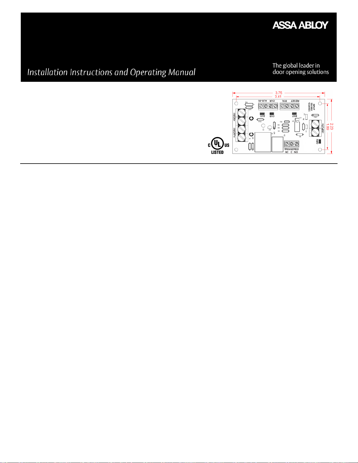
The PDB-FT is available as a module or mounted in an enclosure
with any of our DC Power Supplies.
Module dimensions .......................................... 2.23”W x 3.75”L x .8”H
Mounting holes dimensions ............................................. 1.89” x 3.41”
Weight: ..................................................................................................... 2.2oz
UL Approvals for PDB-FT
UL 294 – Access Control System Unit: Line Security Level I,
Endurance Test Level IV, Standby Power Level I, Attack Test Level I
UL 603 – Power supplies for Use with Burglar-Alarm Systems ULC
S318 – Power supplies for Burglar Alarm Systems
ULC S533 – Standard for Egress Door Securing and Releasing
Devices
Note: for UL compliance the subassembly shall be installed in a
UL Listed 294 or 603 or ULC-S533 or ULC-S318 enclosure.
500-33060_2
2
 Loading...