

Page 1
Securitron Magnalock Corp. www.securitron.com ASSA ABLOY, the global leader
Tel 800.624.5625 techsupport@securitron.com
in door opening solutions
SECURITRON PB5E EXIT BUTTON
INSTALLATION AND OPERATING INSTRUCTIONS
1. DESCRIPTION
The model PB5E is a spring loaded momentary 2" diameter, exit button, mounted on a stainless
steel single gang outlet box cover. The DPDT contacts switch when the button is depressed and
return when it is released. The contacts are UL listed with 5 AMP capacity. The PB5E can be
used for momentary release of fail safe or fail secure electric locks. If interfaced with a release
hold timer, it can provide for timed release of electric locks. It may also be used to input a REX
(request to exit) signal to a card reader system. We recommend that the local building or fire
safety authority be consulted prior to using exit buttons for door egress. They may require a "no
special knowledge" exit device such as Securitron's Touch Sense Bar.
2. INSTALLATION
As the PB5E is an economy version, it is supplied without a retro-fit wall mounting device and
without hookup wire. Connection is made via .250" quick connect terminals found on the rear of
the unit. To connect these terminals, the installer may use p ush on connectors to which wires
are crimped or wires may be directly soldered to the terminals through the hole provided. If a
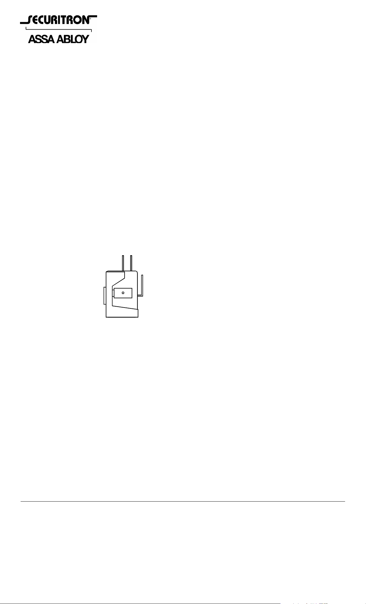
back box is used, the installer should select a box with minimum dep th of 2 1/2". The drawing
below shows identification of the switch's common, normally closed and normally open
terminals. Note, however that an end view of one contact block is shown. The unit has a double
pole, double throw output so there is a second block affixed next to the first with the contacts in
the same orientation.
MODEL PB5E: IDENTIFICATION OF CONTACTS
N.C.
N.O.
NOTE: There are two contact
blocks mounted next to each
COM
other. The termainal I.D. Is
the same on both blocks (one
is shown in the drawing to the
left.)
TERMINAL TYPE: .250” QUICK CONNECT
3. SWITCH ILLUMINATION OPTION
The PB2-LK is a field installable illumination kit intended for the PB2E/PB5E/EEB2 series
pushbuttons which includes the LED, wires and instructions needed to add illumination to the
switch.
4. WIRING
The PB5E can be used in many different ways but the drawings below show three common
applications. The first shows momentary release of a fail safe or fail secure e lectric lock. The
second drawing shows timed release of a fail safe electric lock using the PB5E and Securitron's
TimeMate. Momentarily pressing the button will release the lock for the amount o f time set on
the TimeMate. The wiring is also done in double break fashion so that even if th e timer fa ils, the
button will still be able to momentarily release the lock. This is for added safety. The third
drawing shows interface of the PB5E with an access control system such that a fail safe lock
(generally a magnetic lock) is released for the amount of time programmed into the system in
safe, double break fashion. In this third application, both poles of the PB5E are required. The
NC contacts of the PB5E are connected in series with the NC contacts of the access control
system’s lock control relay and the NO contacts of the PB5E c onnect to the REX input terminals
of the access control system such that when the button is pressed, the access control system
will operate its relay thereby releasing the lock and allowing egress. But if the access control
© Copyright, 2011, all rights reserved PN# 500-19000
Page 1 Rev. E, 04/11
Page 2
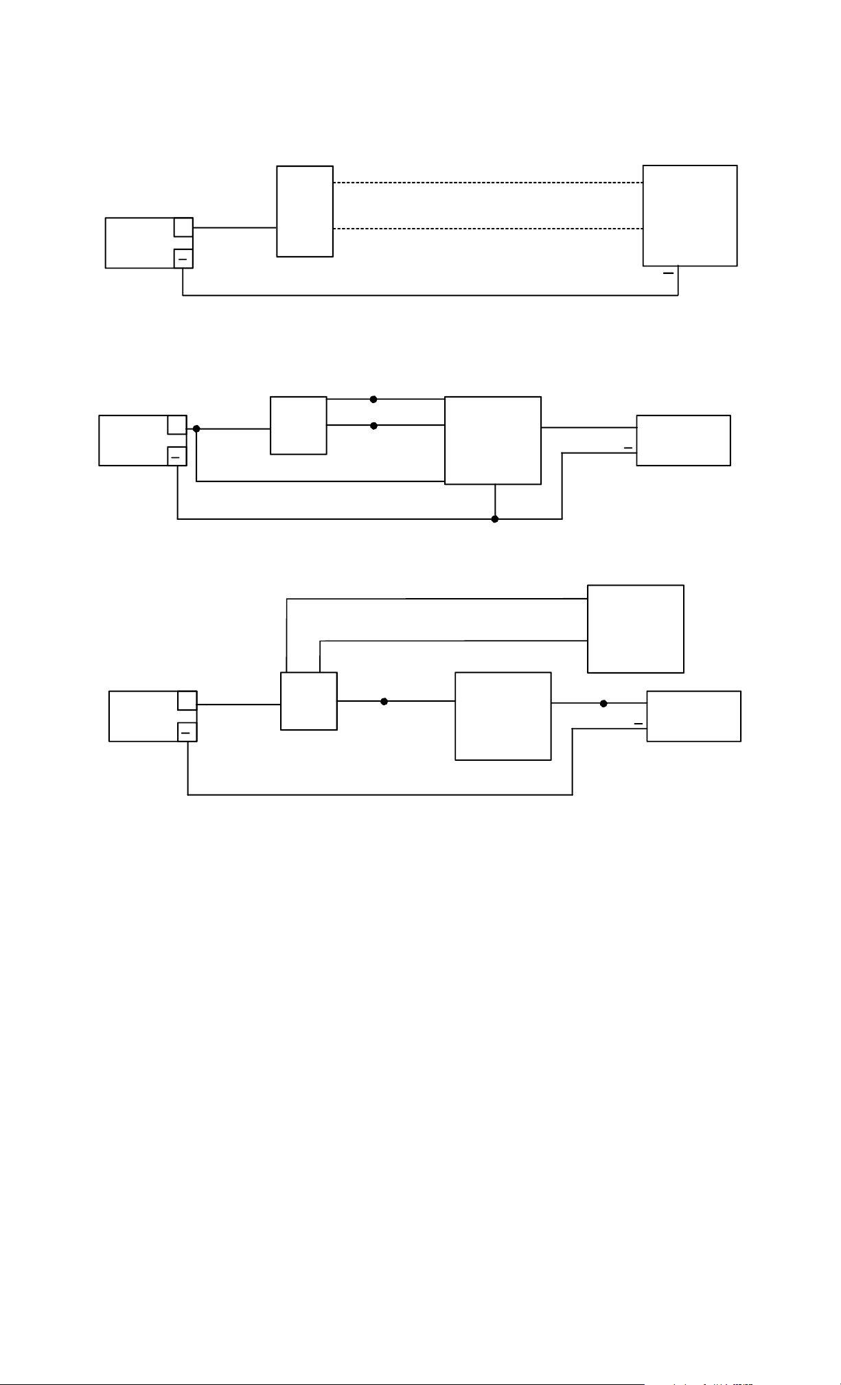
system experiences an electronic failure, the PB5E contacts will sti ll directly release the fail safe
lock for as long as the button is held pressed.
MOMENTARY RELEASE OF FAIL SAFE OR FAIL SECURE ELECTRIC LOCK
IF FAIL SAFE
IF FAIL SECURE
+
+
D.C. LOCK
POWER
SUPPLY
NC
+
COM
PB5E
NO
TIMED DOUBLE BREAK RELEASE OF FAIL SAFE LOCK
POWER
SUPPLY
NO
+
COM
PB5E
NC
YELLOW
WHITE
RED
TIMEMATE
BLACK
GREEN
+
FAIL SAFE
D.C. LOCK
TIMED DOUBLE BREAK: FAIL SAFE LOCK USED WITH ACCESS SYSTEM
ELECTRIC
ACCESS
SYSTEM
REX INPUT
COM 2
NO 2
COM
ACCESS
SYSTEM
RELAY
NC
+
FAIL SAFE
D.C. LOCK
POWER
SUPPLY
+
COM 1
PB5E
NC 1
5. ALTERNATE LENS CHANGING
The pushbutton is factory shipped with the red lens set installed and two lens/insert options.
Changing to the other lens sets is simple.
1) Grasp keyplate and turn over. From the back rotate the white contact block of the switch
counter-clockwise to the 11 o’clock position and pu ll straight back to remove the contact
block.
2) With a slender smooth ended object such as a marker pen, slide it inside the sw itch body.
With the object inserted in the switch up against the lens, place the obj ect on a smooth
surface with the keyplate on top, and tap the keyplate up and down on the object to po p
the lens off. Remove the lens and insert.
3) Turn the keyplate over and place the new insert ont o front of switch, confirm that the text
on the insert is correct reading to the keyplate and place the matching colour lens on top
of the insert and compress around all edges of the lens until it snaps in place. Depress
lens several more times to ensure smooth operation and that the lens is not binding.
4) With the terminals upward insert the contact block back into the back of the switch at the
11 o’clock position and rotate clockwise until it stops straight up and down.
PN# 500-19000
Page 2 Rev. E, 04/11
 Loading...