

Page 1
Securitron Magnalock Corp. www.securitron.com ASSA ABLOY, the global leader
Tel 800.624.5625 techsupport@securitron.com
in door opening solutions
SECURITRON PB4L SERIES EXIT BUTTON
INSTALLATION AND OPERATING INSTRUCTIONS
1. DESCRIPTION
The model PB4L series illuminated exit button is an all steel unit specially designed to resist
vandalism. The button cannot be removed or tampered with from the outside. It is design ed to
resist shocks such as hammer blows. A bi-color indicator LED is included. Part number PB4L
calls out a momentary spring loaded DPDT button on a single gang stainless steel plate with 4
Amp rated contacts. Adding the suffix "N" identifies the same unit on a 1 3/4" w ide narrow sti le
plate. Adding the suffix "A" changes the push button switch to alternate action (push on/push
off).
The PB4L can be used for momentary release of fail safe or fail secure electric locks. If
interfaced with a release hold timer, such as Securitron's TimeMate TM-9, it can provide for
timed release of electric locks. It may also be used to input a REX (request to exit) signal to a
card reader system. We recommend that the local building or fire safety authority be consulted
prior to using exit buttons for door egress. They may require a "no special knowledge" exit
device such as Securitron's Touch Sense Bar.
2. INSTALLATION
The PB4L series comes with a retrofit mounting device and color coded hookup wires installed.
A choice of fasteners is also supplied. The installer may elect to use standard 6-32 slot sc rews
or the 6-32 spanner head screws, which provide a degree of tamper proofing. The drawing
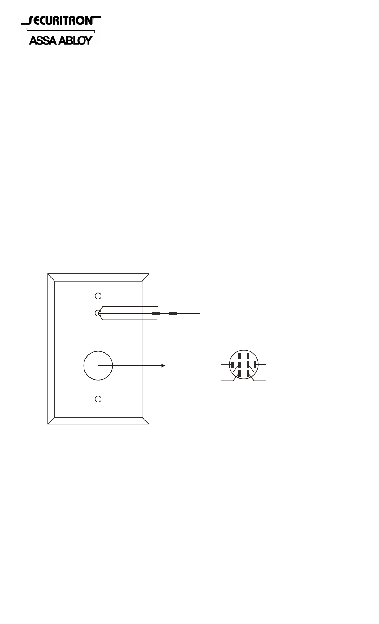
below shows identification of the unit's connection points.
BOTH LED COLORS ON INDICATOR LED
IS FACTORY SET-UP AS 24 VDC
REAR OF UNIT SHOWN
REMOVE THE OUTER RESISTOR TO
OBTAI N 12 VOLT OPERATION
BI-COLOR
LED
GREEN LED WIRE
RED LED WIRE
GREEN (LED +)
WHITE (COM)
PUSHBUTTON LED IS FACTORY SET-UP AS 24 VD C
REMOVE THE OUTER ON
SWIT C H WIR E
BLACK LED WIRE (NOTE RESISTORS)
WIRE IDENTIFICATION
RED (NC)
BLUE (NO)
RESISTOR GREEN
TO OBTAIN 12 VOLT OPERATION
RED/WHITE (NC)
A
L
B
C
BLUE/WH ITE (NO)
WHITE/BLACK (COM)
L
(
K
E
-
D
)
© Copyright, 2011, all rights reserved PN# 500-16150
Page 1 Rev. B, 06/11
Page 2
3. BI-COLOR LED OPERATION
T
The bicolor LED can illuminate red or green and has 3 wires attached to it: Red, Green and
Black. Black is common DC negative. Red is the +VDC input to illuminate red. Green is the
+VDC input to illuminate green. Note that the black wire has 2 resistors on it. If the resistors
are left as they are, the LED will operate on 24 volts. For 12 volt operation, remove
the outer resistor. With this set up, you can use either color for your indicator or even
alternate red and green to show 2 different conditions. The LED's could be operated, for
instance, from an SPDT switch to change colors. You cannot, howev er, drive both sides of
the LED at the same time (the indicator would show orange) or the resistors will be
overloaded. If you need to be able to drive both colors at the same time to display a third
(orange) condition, remove both resistors on the black wire and connect individual resistors on
the red and green wires. The values would be: 620 Ohms 1/2 watt for 12 volts and 1300 Ohms
1 watt for 24 volts.
4. SWITCH LED OPERATION
The switch LED can illuminate green if desired. The black wire is common DC negative, green is
+VDC. The pushbutton is set up from factory as 24VDC. Remove the outer resistor on green
wire to obtain 12VDC operation
5. WIRING
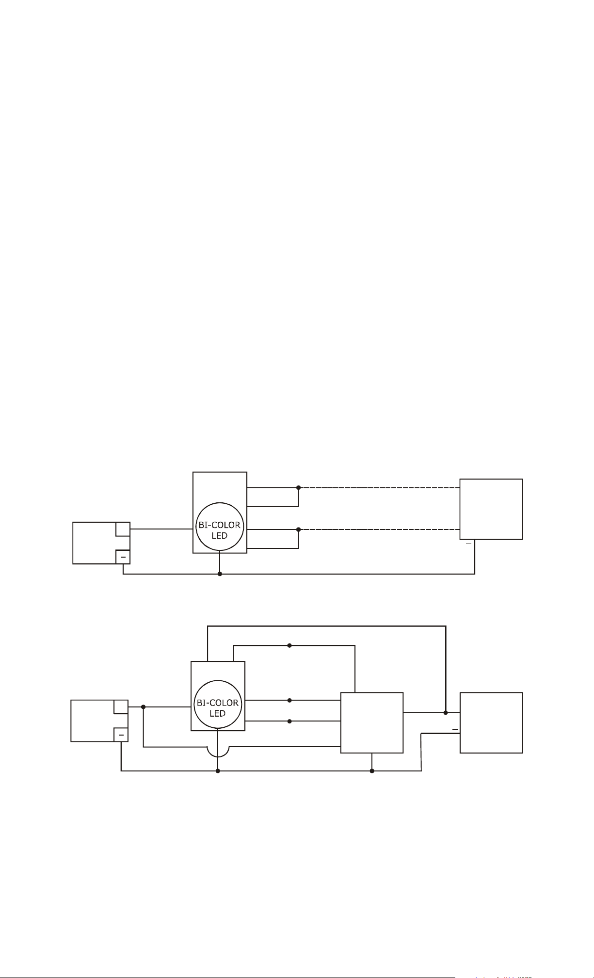
The PB4L can be used in many different ways but the drawings below show two common
applications. The first shows momentary release of a fail safe or fail secure electric lock. The
PB4L indicators are connected so that the green LED is normally on. When the button is
pressed, releasing the lock, the green LED turns off and the red one comes on. The second
drawing shows timed release of a fail safe electric lock using the PB4L and Securitron's
TimeMate. Momentarily pressing the button will release the lock for the amount o f time set on
the TimeMate. The indicator will switch from green to red du ring the lock release period. The
wiring is also done in double break fashion so that even if the timer fails, the button will st ill be
able to momentarily release the lock. This is for added safety.
MOMENTARY RELEASE OF FAIL SAFE OR FAIL SECURE ELECTRIC LOCK
POWER
SUPPLY
POWER
SUPPLY
PB4L
+
+
WHITE
TIMED DOUBLE BREAK RELEAS E OF FAIL SAFE LOCK
GRN/LED
PB4L
WHITE
BLACK/LED
RED
GRN/LED
BLUE
RED/LED
BLACK/LED
RED/LED
BLUE
RED
BLUE
YELLOW
IF FAIL SAFE
IF F AI L SECURE
WHITE
RED
IMEMATE
BLACK
TM-9
GREEN
+
ELECTRIC
D.C. LOCK
+
+
ELECTRIC
D.C. LOCK
PN# 500-16150
Page 2 Rev. B, 06/11
 Loading...