

Securitron M32, M82GBD, M82FGB, M82FBD, M82FB Installation Instructions
...
500-10420, Rev G
10027 S. 51st St. Ste 102
Phoenix, AZ 85044
Tel: 1-800-624-5625
Mon-Fri: 6:00am - 4:00pm PDT
securitron.com
techsupport@securitron.com
Magnalock®
Models M32, M62, and M82B
Installation and Operating Instructions
1

500-10420, Rev G
TABLE OF CONTENTS
INTRODUCTION ............................................................................................. 3
SPECIFICATIONS ........................................................................................... 3
GENERAL ........................................................................................................ 4
Perform a Product Inventory ........................................................................ 4
Have the Recommended Tools ................................................................... 4
Perform a Pre-Installation Survey ................................................................ 4
INSTALLING A MAGNALOCK ......................................................................... 6
Attach the Template and Mark the Drill Holes ............................................. 6
Drill the Holes for the Lock Body and Strike Plate ....................................... 7
Install the Blind Nuts .................................................................................... 8
Install the Strike Plate .................................................................................. 9
Install the Magnalock ................................................................................. 12
Wire Double Door Status ........................................................................... 15
Wire Double Door Status—DPS ................................................................ 15
Wire for Emergency Release ..................................................................... 16
MAINTAINING A MAGNALOCK .................................................................... 16
Perform an Inspection ................................................................................ 16
Clean the Magnalock ................................................................................. 16
TROUBLESHOOTING A MAGNALOCK ........................................................ 17
DETERMINING WIRE GAUGE ...................................................................... 18
WARRANTY .................................................................................................. 20
2

500-10420, Rev G
[
g]
[
g]
[
g]
INTRODUCTION
The Securitron Magnalock® family is state of the art in electromagnetic locking,
and includes operational electrical characteristics and mounting configuration
options addressed in this document.
The BondSTAT “B” Magnalock Series, Bond Sensor, monitors the magnetic field.
An internal sensor activates a single pull double throw (SPDT) dry-contact relay
connection designed for interface to access control and/or alarm systems, which
reports the status of the Magnalock.
The DPS “D” Magnalock Series, Door Position Sensor, is activated by a special
magnetic strike armature assembly. This isolated SPDT reed switch, with an
internal resettable protection device, is designed for interface to access control
and/or alarm system for door status.
SPECIFICATIONS
MODEL M32 M62 M82B
Holding Force:
Dimensions:
Length: 8" [203 mm] 8" [203 mm] 12" [305 mm]
Height:
1.88" [48 mm] 3" [76 mm] 3" [76 mm]
Depth:
1.6" [41 mm] 1.75" [44 mm] 1.75" [44 mm]
Current @ 12 VDC: 300 mA 250 mA 350 mA
600 Pounds (lbs)
272 k
1200 lbs
544 k
1800 lbs
816 k
Current @ 24 VDC: 150 mA 150 mA 200 mA
Capacitance @ 12 VDC: 6.8 mF 44 mF 44 mF
Capacitance @ 24 VDC: 6.8 mF 11 mF 11 mF
Dual Voltage: 12/24 Volts DC
BondSTAT Rating: Voltage: 30 VDC (Maximum) ~ Current: 1 Amp (Maximum)
DPS Rating: Voltage: 30 VDC (Maximum) ~ Current: 125 mA (Maximum)
3
500-10420, Rev G
GENERAL
Perform a Product Inventory
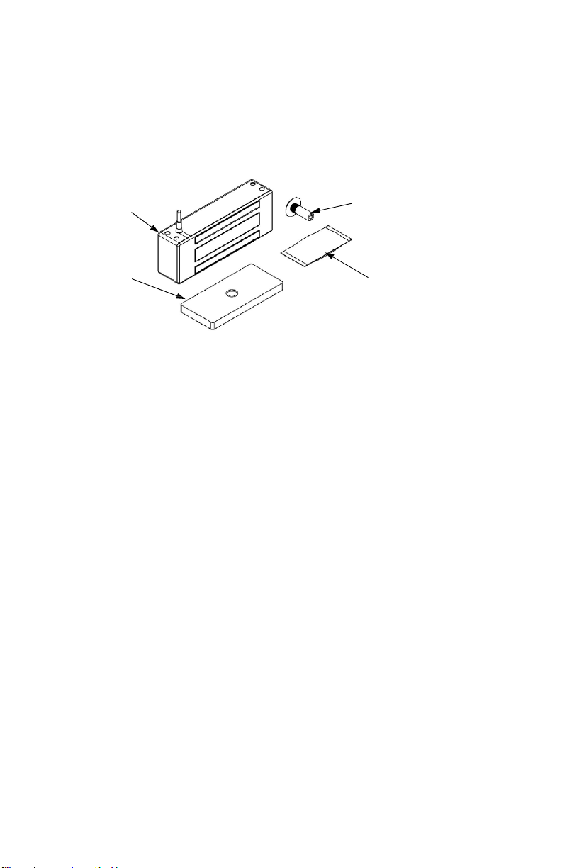
1. Upon unpacking this product, PERFORM an inventory to ensure that all of
the required components and hardware have been included; this should
include the items detailed in Figure 1, “Magnalock Inventory.”
Magnalock
Strike Plate
Sex Bolt
Hardware
Figure 1. Magnalock Inventory
Have the Recommended Tools
1. ENSURE the following recommended tools are available for installation of
the applicable Magnalock:
Power Drill Hammer Wire Strippers/Cutter
1/8”, 3/8”, 1/2” Drill Bits Center Punch Crimp Wire Connectors
Masking Tape Crimp Tool 3/16” Hex Key (Allen Wrench)
Fish Tape or Lead Wire Multimeter 1/2” Open end or Crescent Wrench
Perform a Pre-Installation Survey
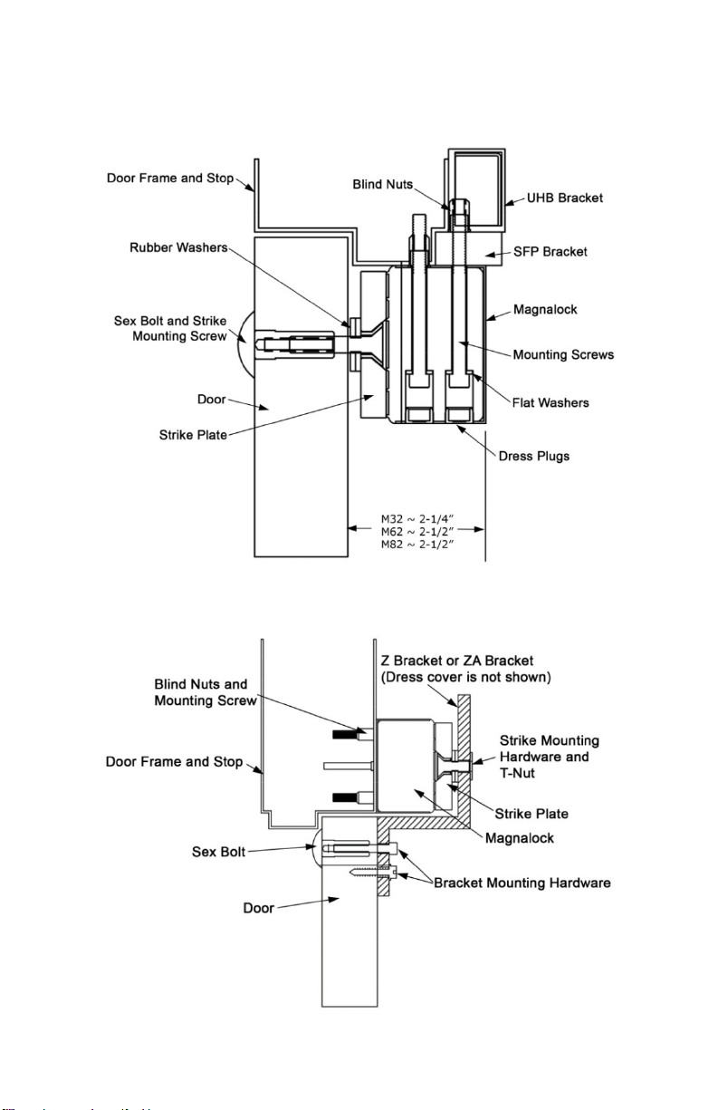
NOTE 1: Additional brackets may be needed for proper installation.
Specialized brackets are available through Securitron and its many
product distributors.
NOTE 2: Figure 2, Magnalock Installation on an Out-Swinging Door,” and
Figure 3, “Magnalock Installation on an In-Swinging Door,” illustrate
the typical mounting methods.
1. PERFORM an initial onsite survey to determine a method of mounting and to
review the installation plan, taking the following into consideration:
• Physical strength of mounting areas should be strong enough to meet or
exceed the holding force of the required Magnalock.
• Placement of the Magnalock wiring and protection from potential
damage due to intruders or vandal’s external attack.
4
500-10420, Rev G
• Accessibility for prevention of potential safety hazards.
Figure 2. Magnalock Installation on an Out-Swinging Door
5

500-10420, Rev G
Figure 3. Magnalock Installation on an In-Swinging Door
INSTALLING A MAGNALOCK
Attach the Template and Mark the Drill Holes
1. SELECT a mounting location for the Magnalock and strike assembly.
NOTE: The edge of the template should be about 1” (25.4 mm) from the latch
side of the door to allow proper access at the mounting locations for
drilling and tool access.
2. ATTACH the template to the
door and frame as shown in
Figure 4, “Attaching the
Template.”
a. IF Installing a strike
plate horizontally,
THEN ENSURE the top
edge of the strike will be
approximately
1/8" [3.2 mm] below the
door frame stop.
Figure 4. Attaching the Template
b. IF the strike and magnet are to be mounted vertically,
THEN INCREASE the clearance between the strike and frame to
3/16" [4.8 mm].
3. WHEN the template is
attached,
THEN MARK the location of
all holes to be drilled using a
center punch (see Figure 5,
“Marking Drill Hole
Locations”).
Figure 5. Marking Drill Hole Locations
6
 Loading...