

Securitron M380EBDX-630, M380EBDX-629, M380EBDX-628, M380EBDX-612, M380EBDX-606 Installation Instructions
...
500-24085, Rev 1
Securitron® M380E Series Magnalock®
With EcoMag™ Technology
Installation Instructions
Models Covered:
M380E
M380EBD
M380EBDX
Phoenix, AZ
Tel: 1.800.626.7590
Mon-Fri: 6:00am - 4:00pm PDT
Fax: 1.800.232.7329
www.assaabloyesh.com
techsupport.esh@assaabloy.com

2 500-24085, Rev 1
RECOMMENDED INSTALLATION TOOLS ...................................................................................................... 3
IN THE BOX CONTENTS .................................................................................................................................. 3
Installation Hardware Pack Contents ............................................................................................................. 4
Strike Installation Hardware Pack Contents ................................................................................................... 4
SPECIFICATIONS ............................................................................................................................................. 5
MAGNALOCK PREPARATION AND INSTALLATION ..................................................................................... 5
Performing a Pre-Installation Survey .............................................................................................................. 5
Removing the Cover ...................................................................................................................................... 6
Positioning the PIR REX Module in the Magnalock ........................................................................................ 6
Preparing the Magnalock ............................................................................................................................... 7
Installing Magnalock on a Metal Door Frame ............................................................................................ 9/10
Installing Magnalock on a Wood Door Frame ............................................................................................ 9/14
Assembling the Lock to the Bracket and Adjusting, as Necessary................................................................ 17
MAGNALOCK ELECTRICAL INSTALLATION ............................................................................................... 18
Preparing the Magnalock ............................................................................................................................. 18
Locating and Setting the Dip Switches on the Magnalock ............................................................................ 19
Magnalock Operation with Access Control System ...................................................................................... 20
Magnalock Operation with Local Control ...................................................................................................... 20
Locating and Setting the Jumpers on the Magnalock ................................................................................... 20
Documenting the Configuration Settings ...................................................................................................... 21
Pulling the Wiring ................................................................................................................................ ......... 22
Connecting the Final Wiring ......................................................................................................................... 22
Dual Lock (Double Door) Wiring ................................................................................................................... 24
Performing Initial Calibration ........................................................................................................................ 26
Verifying PIR Coverage and Adjusting the PIR Coverage, as Needed ......................................................... 26
Re-Installing the Lock Cover ........................................................................................................................ 28
TROUBLESHOOTING .................................................................................................................................... 29
LED Behavior ............................................................................................................................................... 29
Returning the Magnalock to Factory Default Settings ................................................................................... 29
WARRANTY .................................................................................................................................................... 31
3 500-24085, Rev 1
RECOMMENDED INSTALLATION TOOLS
Masking Tape Measuring Device #1 and #2 Phillips Screwdrivers
Mini Phillips Screwdriver 1/2” Open End or Crescent Wrench, Wire Strippers/Cutter
or BlindNut Installation Tool
Pencil/Pen Center Punch 3/16” Hex (Allen) Wrench
Multimeter Fish Tape or Lead Wire
Rubber Mallet Drill Bits: #36 (0.107”), 3/16”, 7/32”, 3/8”, 1/2”, and 5/8”
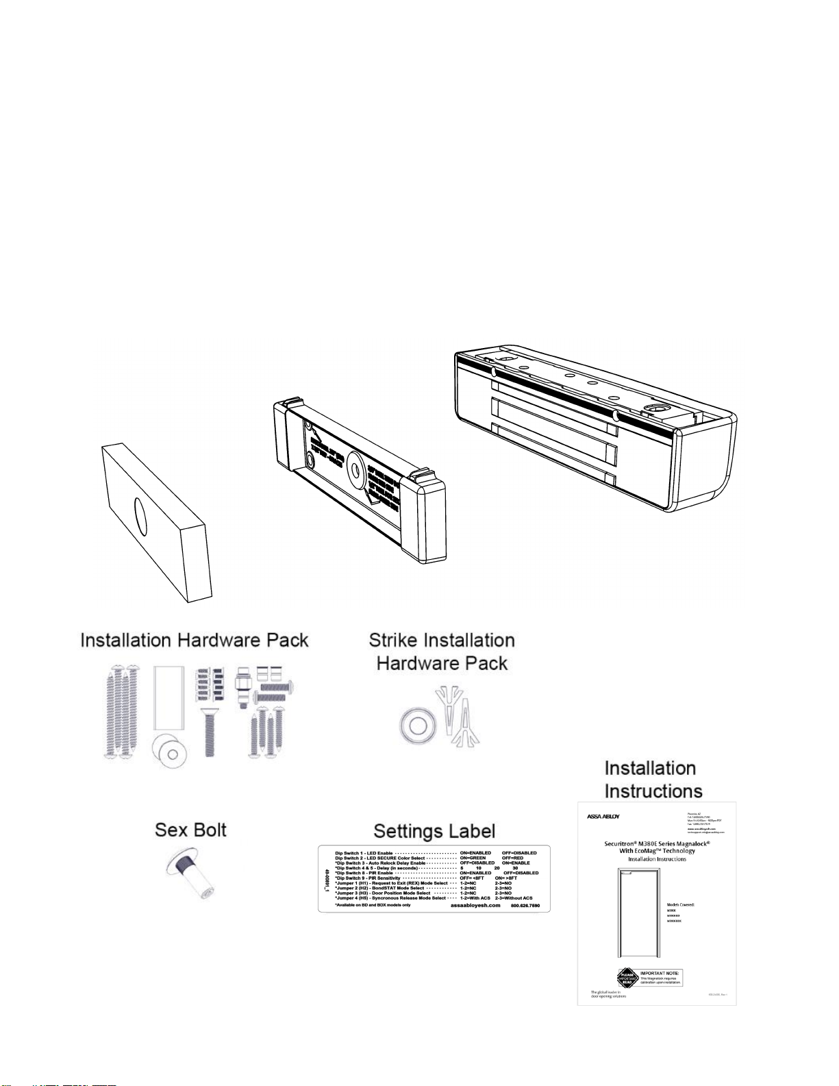
IN THE BOX CONTENTS
Strike Plate
Strike Plate
Housing
Magnalock and
Mounting Bracket

4 500-24085, Rev 1
Installation Hardware Pack Contents
NOTE: Hardware is provided for various installations. There will be leftover parts depending on the type of installation.
#14 x 3” Type A
Phillips Pan Head Screw (4)
#12 x 1-1/2” Type A Phillips
Pan Head Screw (4)
5/16-18 x 1-3/4”
Flat Head Socket Screw
Threadlock
1/4-20 x 1” Phillips
Pan Head Screw (2)
#6 x 1/2” Phillips Flat Head
Type A Steel Screw (6)
6-32 x 3/8” Phillips Flat Head
Type F Steel Screw (6)
Blind Nut Install
Hardware Assembly
1/4-20 Blind Nut (2)
Neoprene Washer (2)
Strike Installation Hardware Pack Contents
Strike Spring Assembly
Template Pins (2)

5 500-24085, Rev 1
SPECIFICATIONS
Mechanical
Physical Size:
Height: 2.20” [56 mm]
Depth: 2.45” [62 mm]
Length: 10.00” [254 mm]
Shipped Weight:
6.5 lb [2.95 kg]
Static Holding Force (Maximum):
600 lbs [272 kg]
UL Tested Ratings:
Static Holding Force:
500 lbs [227 kg]
Dynamic Holding Force:
50 ft-lbs [68 J]
Endurance:
250,000 cycles
Electrical
IMPORTANT: UL 294 compliance requires that the locking device be powered by a UL 294 (ALVY) or UL 603 (APHV) listed
power supply and shall be installed in accordance with the following UL and National Standards:
NFPA 70 – National Electrical Code
Input Voltage:
(VDC +/- 10%)
12 through 24 VDC. Power must be at least rectified
and filtered to meet minimum electrical specifications.
AC, Half Wave, and Full Wave power is unacceptable.
Tamper Rating:
Voltage – 30 VDC (Maximum) (Resistive)
Current – 1A (Maximum)
DPS Rating:
Voltage – 30 VDC (Maximum) (Resistive)
Current – 125 mA (Maximum)
REX Rating:
Voltage – 24 VDC
Current – 1A (Resistive)
Current by Model Number
Average Power Draw
(12/24VDC)
Maximum Power Draw
(12/24 VDC)
M380E
140/90 mA
585/310 mA
M380EBD
140/90 mA
585/310 mA
M380EBDX
150/100 mA
610/320 mA
IMPORTANT: Size your power supply to handle the UL verified maximum power draw.
Environmental (Indoor Use)
Operating Temperature:
32ºF to 110ºF [0ºC to 43ºC]
Humidity:
10% to 90% RH
IMPORTANT: This product must be installed according to all applicable building and life safety codes.
UL 294 Performance levels: Access Control Line Security Level 1, Destructive Attack Level 1, Endurance Level IV, Standby Power
Level 1.
MAGNALOCK PREPARATION AND INSTALLATION
Performing a Pre-Installation Survey
1. Before installing the Magnalock, DETERMINE and ASSESS the mounting location for the following:
• Physical strength of the frame— it should be strong enough to meet or exceed the holding force of the
Magnalock.
• Frame and vicinity— it should offer protection for the wiring to prevent vandalism, and adequate protection from
rain exposure.
6 500-24085, Rev 1
• Door inspection—it should be inspected for any obstacles that may interfere when mounting the strike plate.
• Proper mounting—The Magnalock comes with factory default mounting for use with an outswing door. ASSA
ABLOY ESH should be contacted for available brackets for other installation configurations.
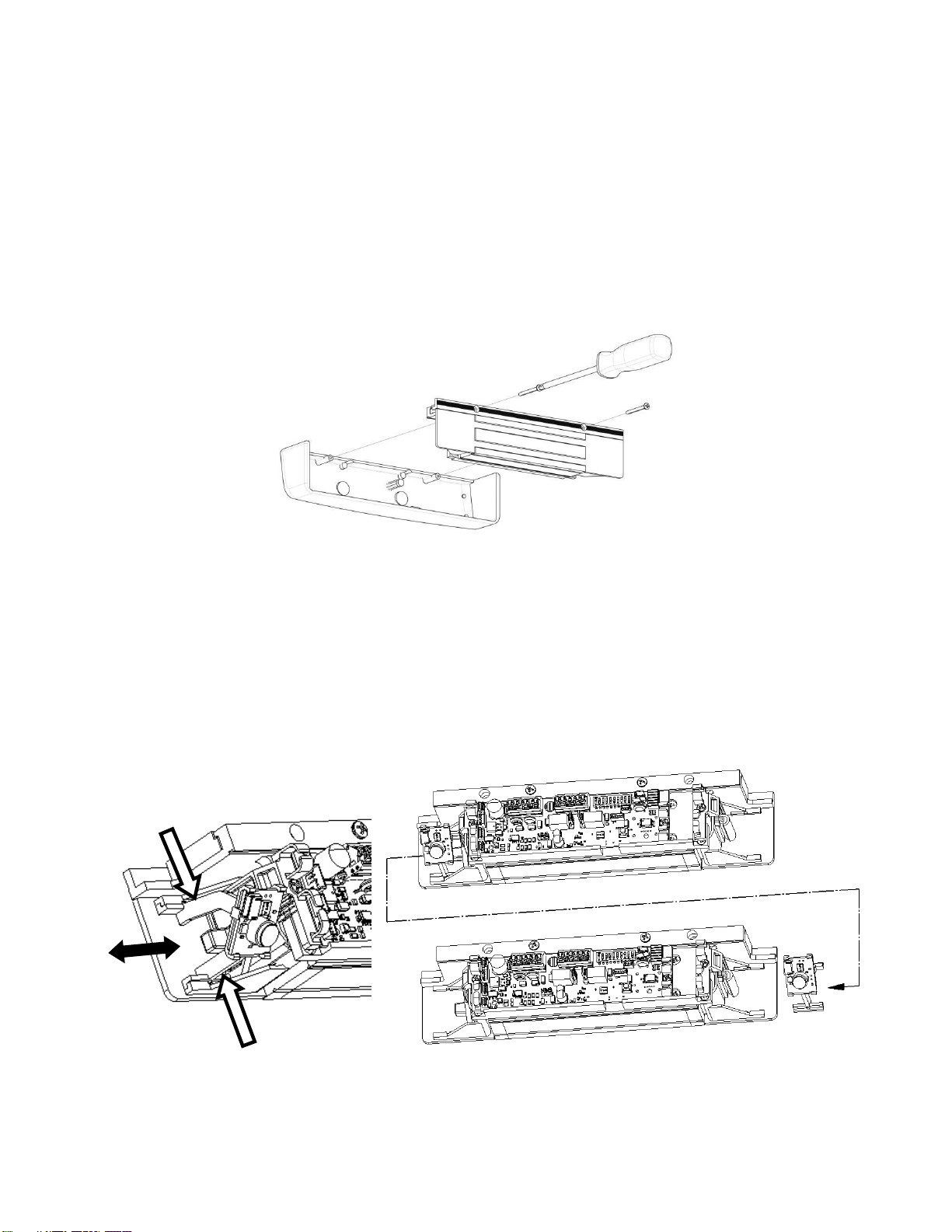
Removing the Cover
NOTE: Removing the cover provides access to the circuit board on the back of the magnet.
1. Using a Phillips screwdriver, REMOVE the two (2) screws securing the cover, as shown in Figure 1, “Removing the
Cover Screws.”
2. SET the screws aside to re-attach the cover later.
Figure 1. Removing the Cover Screws
Positioning the PIR REX Module in The Magnalock
NOTE 1: The physical position of the PIR REX module of an M380EBDX model may be reconfigured for either end of
the Magnalock, as desired.
1. To remove or install the module, compress the legs of the support bracket and slide the bracket into or out of the
retaining rails at either end of the lock (see Figure 2, “Removing and Installing the PIR REX Module”).
Figure 2. Removing and Installing the PIR REX Module
7 500-24085, Rev 1
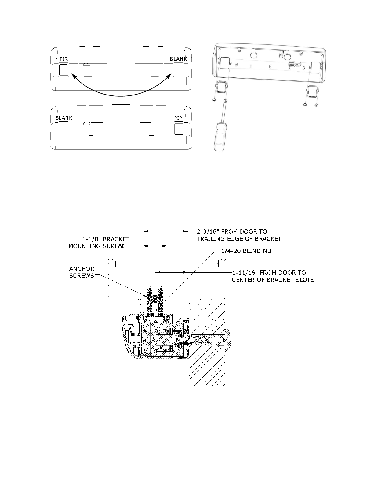
2. Remove, reposition and reinstall the inserts into the lock cover as necessary using a #1 Phillips screwdriver (see
Figure 3, “Removing, Repositioning and Reinstalling the Cover Inserts”).
Figure 3. Removing, Repositioning and Reinstalling the Cover Inserts
Preparing the Magnalock
1. ENSURE you have at least 2-3/16” between the closed door and the edge of the header. If not, you will require additional bracketry
(see Figure 4, “Assessing the Installation Site”).
Figure 4. Assessing the Installation Site

8 500-24085, Rev 1
2. REMOVE the two (2) screws securing the lock to the mounting bracket and SLIDE the bracket from the top of the lock chassis (see
Figure 5, “Removing the Securing Screws”).
Figure 5. Removing the Securing Screws
3. PINCH and INSERT the template pins flush into the dovetail slots of the mounting bracket (see Figure 6, “Inserting the Template
Pins”).
Figure 6. Inserting the Template Pins
4. PERFORM the following to mark the mounting holes:
a. APPLY masking tape to the door and frame surfaces to protect from any possible damage during marking and drilling.
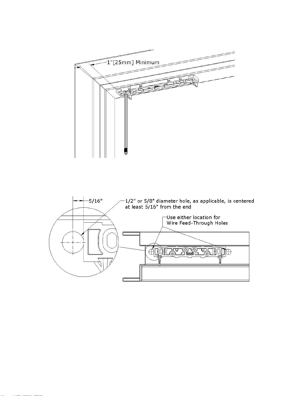
b. PLACE the mounting bracket on the secure side of the door against the frame stop and towards the side of the door that does
not have hinges, and has a minimum of 1” clearance from the frame.
c. CLOSE the door and ADJUST the bracket so that the template pins rest against the door.
9 500-24085, Rev 1
d. MARK the frame through the two (2) oblong bracket mounting holes (see Figure 7, “Marking the Frame”).
Figure 7. Marking the Frame
5. MARK the frame for wire feed-through hole at the end closest to where the wire run will be accessed, and ENSURE
the hole marking is centered at least 5/16” from the end (see Figure 8, “Position of Wire Feed-Through Holes”).
Figure 8. Position of Wire Feed-Through Holes
6. REMOVE mounting bracket from frame.
INSTALLING MAGNALOCK ON A METAL DOOR FRAME
1. GO TO “Installing Magnalock on a Metal Door Frame” section.
INSTALLING MAGNALOCK ON A WOOD DOOR FRAME
1. GO TO “Installing Magnalock on a Wood Door Frame” section.
10 500-24085, Rev 1
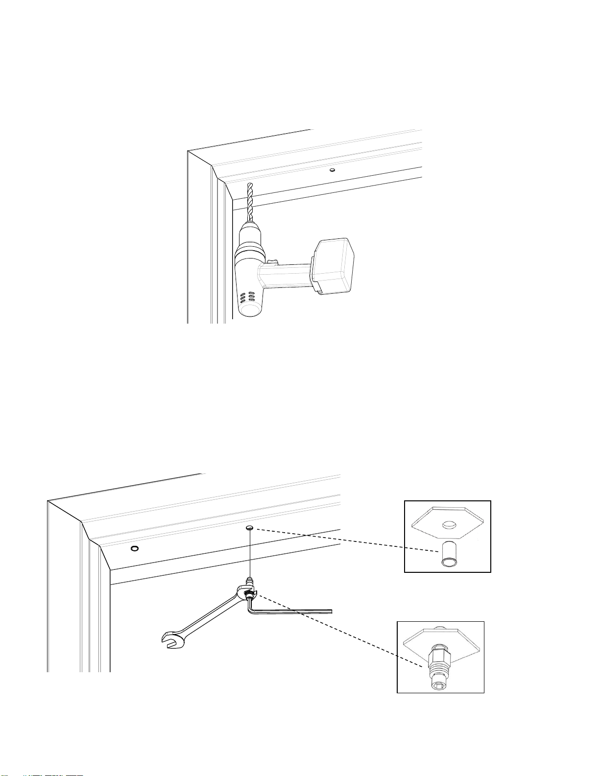
Installing Magnalock on a Metal Door Frame
NOTE: Drilling a pilot hole first or using a step bit will ensure a snug fit for the blind nuts.
1. DRILL two (2) 3/8” diameter holes at bracket-mounting hole marks (see Figure 9, “Drilling the Bracket Mounting
Holes”); DO NOT oversize.
NOTE 1: Blind nuts provide a highly secure and tamper resistant system for mounting and are the mounting hardware provided for
this unit.
NOTE 2: A blind nut installation tool (Securitron BPT-2, “Blind Nut PlacementTool,” or by others) can be used instead of using the
open end wrench and hex wrench.
2. INSTALL blind nut into each 3/8” diameter hole using the provided tool (see Figure 10, “Installing the Blind Nuts”).
a. HOLD the collapsing nut with a 1/2” open end wrench.
b. MAINTAIN pressure on the mounting surface, TIGHTEN the cap screw using a 3/16” hex wrench, and COLLAPSE the blind
nut.
Figure 10. Installing the Blind Nuts
Figure 9. Drilling the Bracket Mounting Holes
 Loading...