

Securitron M380BDX, M380BDX-612, M380BDX-606, M380BDX-605, M380BDX-335 Installation Instructions
...
MAGNALOCK®
M380BDC/M380BDC2/M380BDX/
M380BDCX/M380BDC2X
Installation Instructions
1 500-23310, Rev C

Table of Contents
Warranty ............................................................................................................... 3
Package Contents ................................................................................................ 4
Mounting Hardware .............................................................................................. 4
Recommended Tools ........................................................................................... 5
Specifications ....................................................................................................... 5
Magnalock Preparation and Installation ............................................................... 6
Performing a Pre-Installation Survey................................................................ 6
Positioning the Camera and PIR REX Module Locations in the Magnalock..... 6
Preparing the Magnalock ................................................................................. 9
Locating and Setting the Components ........................................................... 10
Documenting the Configuration Settings ........................................................ 15
Installing the Magnalock................................................................................. 17
Installing the Strike ......................................................................................... 21
Assembling the Lock to the Bracket and Adjusting, as Necessary ................. 25
Performing Final Installation ........................................................................... 27
Performing the Final Wiring ............................................................................ 28
Magnalock Operation With Access Control System ........................................... 32
Magnalock Operation With Local Control ........................................................... 33
Magnalock Maintenance..................................................................................... 33
Proper Cleaning Methods ................................................................................... 33
Troubleshooting Guide ....................................................................................... 34
LED Error Codes ................................................................................................ 35
YouTube Channel: SecuritronAccess
Watch the overall installation
http://tinyurl.com/M380video
2 500-23310, Rev C

Warranty
The MAGNALOCK® series of locks are covered by the MagnaCare®
lifetime replacement no fault warranty. No registration is required.
Product will be replaced forever, for any reason, including but not limited
to installation error, vandalism, or act of God. Replacement product is
shipped at Securitron’s expense next day air if needed.
For more information, visit www.securitron.com
3 500-23310, Rev C
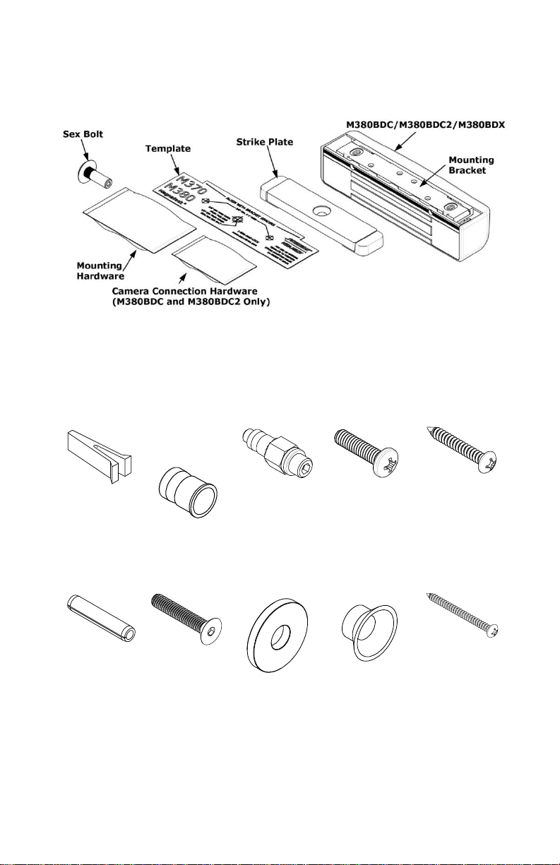
Package Contents
(2) x Bracket
Spacer
(2) x 1/4-20
Blind Nut
(1) x – Blind Nut
Installation Tool
(2) x 1/4-20 x 1”
Phillips Pan Head
(4) x #12 x 1-1/2”
Type A Phillips Pan
Head
(2) x 1/4” x 1-1/4”
Roll Pin
(1) x 5/16-18 x 1-
3/4” Flat Head
Socket
(3) x – Neoprene
Washer
(1) x Plastic Strike
Bushing
(4) x #14 x 3”
Type A Phillips
Pan Head
Mounting Hardware
4 500-23310, Rev C

Recommended Tools
Specifications
Mechanical
Electrical
Environmental
(Recommended)
Physical Size:
Height: 2.20” [56mm]
Depth: 2.45” [62mm]
Length: 10.00” [254mm]
Input Voltage:
12/24 VDC. Power
must be at least
Rectified and Filtered
to meet minimum
electrical
specifications. AC,
Half Wave, and Full
Wave power is
unacceptable.
Magnalock Current
12 VDC/550 mA
(±10%)
24 VDC/300 mA
(±10%)
Optional Camera
Current
12 VDC/200 mA
(±10%)
24 VDC/80 mA (±10%)
Optional Passive
Infrared (PIR) Current
12 VDC/25 mA (±10%)
24 VDC/10 mA (±10%)
Operating Temperature
32ºF to 110ºF [0ºC to 43ºC]
Humidity
10% to 90% RH
Camera
Specifications
Color Version:
Horizontal Resolution: 520 TV
Lines
Video Output: 1 V
P-P
, 75Ω
Minimum Illumination: 1.5 LUX
Black and White Version:
Horizontal Resolution: 420 TV
Lines
Video Output: 1 V
P-P
, 75Ω
Minimum Illumination: 0.1 LUX
Shipped Weight:
Weight: 6.5 lb
Holding Force
(Maximum):
600 lbs [272 kg]
UL Tested Ratings:
Static Holding Force:
500 lbs [227 kg]
Dynamic Holding Force:
50 ft-lbs [68 J]
Endurance: 250,000
cycles
Masking Tape
#1 and #2 Phillips
Screwdrivers
Hammer
Measuring Device
1/2” Open End or Crescent
Wrench
Pencil/Pen
Center Punch
Wire Strippers/Cutter
Multimeter
Fish Tape or Lead
Wire
3/16” Hex (Allen) Wrench
Drill bits: 3/16”, 7/32” (wood frames only), 3/8”, 1/2”
5 500-23310, Rev C

Magnalock Preparation and Installation
Performing a Pre-Installation Survey
1. Before installing the Magnalock, DETERMINE and ASSESS the
mounting location for the following:
• Physical strength of the frame— it should be strong enough
to meet or exceed the holding force of the Magnalock.
• Frame and vicinity— it should offer protection for the wiring to
prevent vandalism.
• Door inspection—it should be inspected for any obstacles that
may interfere when mounting the strike plate.
• Proper mounting—The Magnalock M380 comes with factory
default mounting for use with an outswing door. Securitron
should be contacted for available brackets for other
installation configurations.
Positioning the Camera and PIR REX Module Locations in the Magnalock
NOTE 1: The physical position of the camera or PIR REX Module may
be reconfigured for either end of the Magnalock, as desired.
NOTE 2: If the Magnalock is equipped with both camera and PIR,
each module position may be reversed from the factory
default positions (see Figure 1, “Camera and PIR
Reversing.”
6 500-23310, Rev C
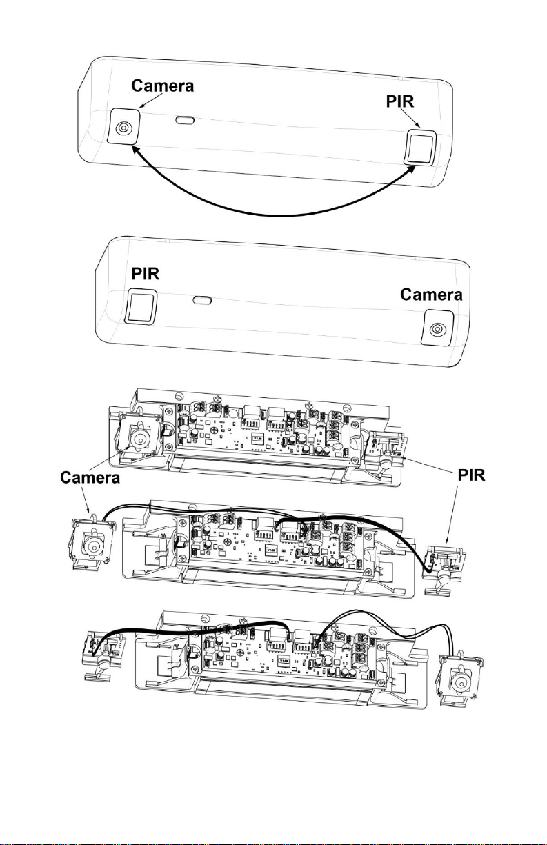
Figure 1. Camera and PIR Reversing
7 500-23310, Rev C
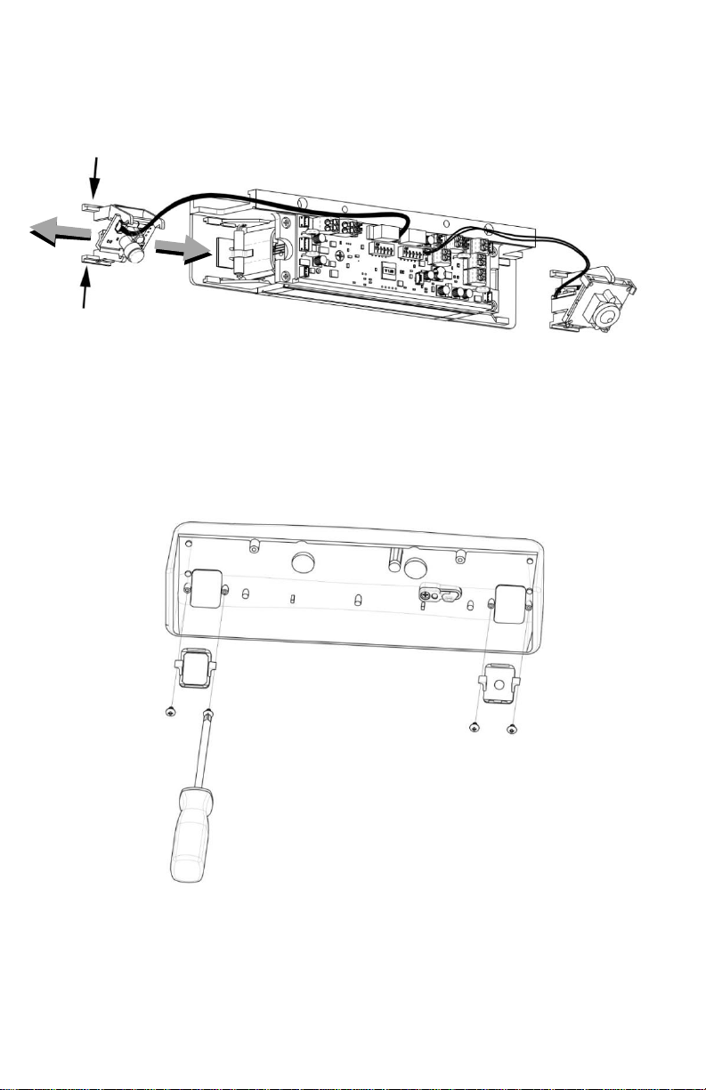
1. To remove or install a module, COMPRESS the legs of the support
bracket and SLIDE the module bracket in or out of the retaining rails
(see Figure 2, “Removing and Installing a Module”).
Figure 2. Removing and Installing a Module
2. REMOVE, REPOSITION, and REINSTALL the module inserts in the
cover, as necessary, using a #1 Phillips screwdriver (see Figure 3,
“Removing, Repositioning, and Reinstalling the Module Inserts.”
Figure 3. Removing, Repositioning, and Reinstalling the Module Inserts
8 500-23310, Rev C
Preparing the Magnalock
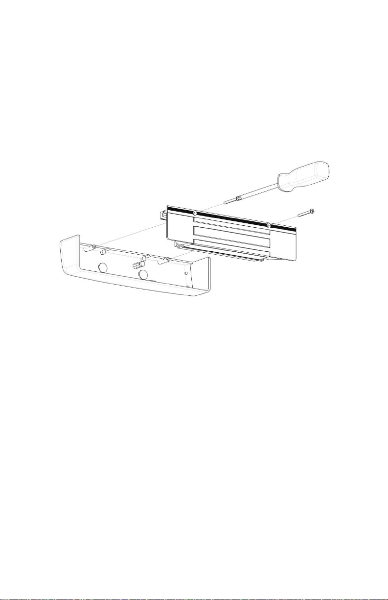
NOTE: Removing the cover provides access to the circuit board and
on the back of the magnet.
1. Using a Phillips screwdriver, REMOVE the two (2) screws securing
the cover, as shown in Figure 4, “Removing the Cover Screws.”
2. SET the screws aside to re-attach the cover later.
Figure 4. Removing the Cover Screws
9 500-23310, Rev C
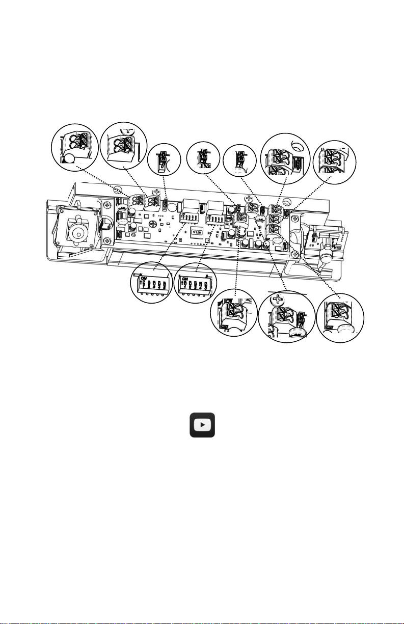
Locating and Setting the Components
J9
J8
JP3
JP4
JP1
J7
J2
SW3
SW1
J6
J12
J3
1. LOCATE and SET the components in the M380 using Figure 5,
“Component Locations,” and Table 1, “Component Label, Name,
Selection, and Position.”
Figure 5. Component Locations
YouTube Channel: SecuritronAccess
Component Configuration
http://tinyurl.com/M380video1
10 500-23310, Rev C
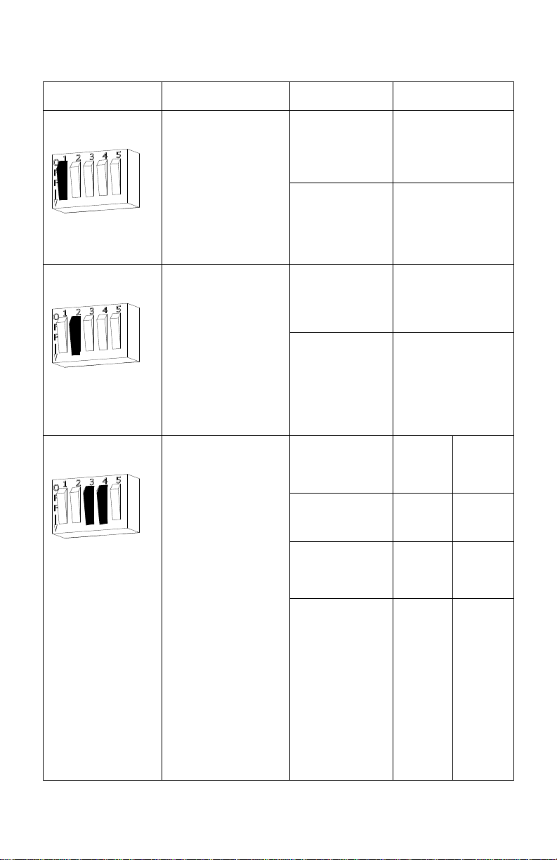
Table 1. Component Label, Name, Selection, and Position
Component Label
Component Name
Selection
Position
SW3
DIP Switch SW3.1:
LED Enable
Position 1 setting of
the DIP switch
enables or disables
the display of the
LED for lock status.
ON = LED
ENABLED
(default setting)
Position 1 ON
(default)
OFF = LED
DISABLED
Position 1 OFF
SW3
DIP Switch SW3.2:
LED Color Select
Position 2 setting of
the DIP switch
controls the color of
the LED output.
Output options are
red or green.
ON = SECURE
= RED
Position 2 ON
OFF =
SECURE =
GREEN
(default setting)
Position 2 OFF
(default)
SW3
DIP Switch SW3.3,
SW3.4:
NOTE: If the
system is using an
access control
system, the relock
timer must be set to
a minimum time.
Relock Delay
Timer:
The Auto Relock
Delay can be
adjusted by
selecting a time
delay with position
3 and position 4 of
SW3.
1/2 second
delay (default)
Position
3 OFF
Position
4 OFF
3 second delay
Position
3 OFF
Position
4 ON
7 second delay
Position
3 ON
Position
4 OFF
15 second
delay
Position
3 ON
Position
4 ON
11 500-23310, Rev C
 Loading...