

Page 1
Integ rat ed Mo vement Exit Del ay
System with Advanced Technology
Models iMXDa and iEXDa
Inst al l at ion I nst ru cti o ns an d User’s Guide
1 500-22155, Rev B
Page 2

TABLE OF CONTENTS
TA BLE O F CONTE NTS ......................................................................2
WARRANTY.......................................................................................4
INTRODUCTION ................................................................................5
SPECIFICATIONS ..............................................................................5
PRODUCT OVERVIEW ......................................................................6
REC OM ME NDE D TOO LS ...................................................................6
INSTALLATION ..................................................................................7
Perf orm ing a P re-Instal lation Survey ................................................7
Configuring t he Mount i ng.................................................................7
Mount i ng the Stri ke .........................................................................8
Mount i ng the Actuator ...................................................................10
Mount i ng the Lock Hous i ng ...........................................................10
Installing t he B l i nd Nuts .................................................................12
Repl acing t he Mortis e Cylinder an d Cam ........................................13
General.....................................................................................13
Al ternate Cy lind ers ....................................................................13
Al ternate Cams .........................................................................13
Inst al l ing t he Elec tric al Conn ecti ons ...............................................14
Gen eral Charac te ris ti cs..............................................................14
El ec tric al S tanda rds...................................................................14
Sens or Ranges (Electrical).........................................................14
Electrical Wiring ........................................................................15
Power Supply Connecti ons ........................................................15
Em ergency Release ..................................................................17
SYSTEM OPERATIONS ...................................................................17
Gen eral Operati ons Des cript i on .....................................................17
Com ponent Lay out........................................................................18
2 500-22155, Rev B
Page 3

Power On Reset ........................................................................18
Inte grat ed Res et /Bypass (IRB) Key Switch..................................18
St andard Ope rational Mode .......................................................18
Bypass Mode — IRB (or External) ..............................................19
Reset — IRB (or E xte rnal)..........................................................19
System Functions .........................................................................19
General.....................................................................................19
Nuis anc e Delay Alarm (NDA) — DIP Swi t ches SW 1 and S W2 .....21
Irrevocable A l arm (I RA ) — DIP Switc h SW 3 ................................21
Bypass Delay Time (BDT) — DIP S wi t ch es SW4 and S W5 ..........21
Post A l a rm Rem i nder (P AR ) — DIP Switch SW6 .........................22
Bypass Expirat ion Alarm (B EA) — D IP Switch SW7.....................22
Manual/ Delay ed Reloc k (MDR ) — DIP Switch SW8 .....................22
Alarms .........................................................................................22
Int ern al (Local) Al arm ................................................................22
External (Remot e) A l arm............................................................22
Control Wiring...............................................................................22
W i ring Layo ut ............................................................................22
External Cont rols .......................................................................25
External Init i at e (i EXDa) .............................................................25
Tamper Status (JP1) a nd Doo r S tatus (JP2 ) wi ring ......................25
W i re Gauge a nd Length ................................................................25
General.....................................................................................25
Determini ng Wire Gaug e and Length ..........................................26
Adj us ting t he Gap (iMXD a only) .........................................................27
Ins talli ng t he EXD-1L Label ...............................................................28
Speciali zed Mounti ng B rac kets ..........................................................28
Ope rat i onal In format i on .....................................................................28
St ate of Cal ifor ni a – iMXDa-CA ..................................................28
3 500-22155, Rev B
Page 4

Cit y of Chi cago – iMXDa-CH ......................................................29
MAGNA LOCK MAINTENANCE .........................................................30
Perf orm ing an I ns pect ion ...............................................................30
Clea ni ng t he M agnaloc k ................................................................30
TROUBLESHOOTING ......................................................................30
WARRANTY
The iMXDa an d i EXDa ar e covered by the M agnaCar e® lifetime
replac ement no faul t warra nty. No registrati on i s require d. Produc t will
be repl aced foreve r, for any reason, i ncluding but not lim i ted to i nstal lation
error, vandali sm, or act of God. Replac em ent pr oduct i s shi pped at
Securitron’ s expense n ext day ai r i f needed.
For m ore inf orm ation, visit
www.securitron.com
4 500-22155, Rev B
Page 5

INTRODUCTION
1200
Length
Height
Depth
12
370
32 mF at
1/8”
Voltage:
The S ec ur itron iMXDa is an int egr ated system incorpor ating Magnalock®
reliabilit y with all-in-one exit delay. This sy stem incorporates Securitron’s
BondSTAT and DPS [Door P os ition Sensor] tec hnology along with intelligent
microprocessor-based, alarm options a nd a trainable door movement feature.
The unit f eatures auto-sensin g dual voltage (12 VDC or 24 VDC) and pr ovides a
variet y of selectable operating f unc tions. The iEXDa is an externally triggered
exit delay unit that r equir es no moveme nt and can be used with Securitr on’s
Touc h S ense Bar series of electronic exit bars a s we ll as other ma nufacturer’s
mechanical exit bars equipped wit h Request t o E xit (REX) switc hes. T he iE XDa
includes all of the impr ovements f ound on the iMXDa.
Secur itron also off er a City of Chicago- and S tat e of Calif ornia-compliant
versions.
This ma nual is intended t o pr ovide the installat ion/ mou nting configurations,
elect r ic al requir eme nts, f unc tional options, and selec tab le setting s re quir ed to
succ essf ully install an iMXDa or iEXDa integrated movement exit delay door
system.
IMPORTAN T: This product must be installed according to all applicable
bui ld ing and life saf et y cod es!
SPECIFICATIONS
Holding Force
Dimens ions:
Dual Voltage:
Current Draw:
Capacitance:
Door Movement (Gap)
Sensing Range
External Alarm Rating
5 500-22155, Rev B
Lbs [544 kg]
12.5” [318 mm]
3.63 [92 m m]
2” [51 mm]
VDC/24 VDC
mA at 12 VDC; 270 mA at 24 VDC
both 12 VDC and 24 VD C.
[3.2 mm] to 1” [25.4 mm]
30 VDC (Maximu m); Current: 1 Amp (Maximum)
Page 6
DPS Rating
Voltage:
Voltage:
≥ 85 dB at 12”
15 pounds
30 VDC (Maximu m); Current: 125 mA (Maximu m)
Tampe r (TS) Rating
Piezo Sounder:
Shipping Weight
30 VDC (Maximu m); Current: 2 Amps (Maximu m)
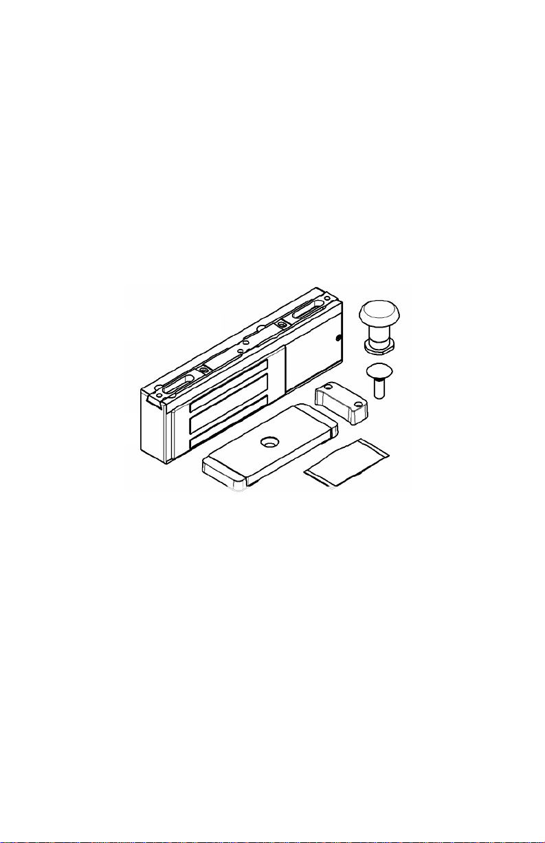
PRODUCT OVERVIEW
Along wit h the installat ion and operating instruc tion manual, the quic k star t guide,
and the mou nting t emp lates, t he pr oduc t package sh ould include the following:
Mounting Bracket
Lock Housing
(DPS) Strike Plate
Figure 1. Product Overview
SB-MXD Sex Bolt
(iMXDa)
Standard
(iEXDa)
Actuator
Hardware Pack
Sex Bolt
RECOMMENDED TOOLS
The following are the recommended t ools for installation:
6 500-22155, Rev B
• Hammer
• Center P unch
• Power Drill
• Drill Bits: 9/64” , 3/ 16” , 7/ 32” , 3/ 8” , 1/ 2” (iE XDa), and 1” ( iM XDa)
• Wrenches: 7/16” open end or adjustable
1/2" box/open end or adjustable
1-1/4” open end or 12” adjustable
3/16” hex key (A llen)
3/32” hex key (A llen)
• Pliers, vise grip
• Screwdrivers: #1, #2, and #3 Phillips
1/8” flat blade
Page 7
• Masking Tape
• Fish Tape or Lead Wire
• Wir e S trippers/ Cutt er
• Multimeter
INSTALLATION
Pe rfo rmi ng a Pr e-Installation Survey
1. PERFORM a pre-inst allatio n s ur vey to det er min e the mounting location
ba sed o n the f ollowing:
• Physical strength of mo unting areas sho uld me et or exc eed the holding
for c e of t he iM XDa/iEXDa.
• Lock wir ing should be routed for pr otection f r om d amag e due to
intrusio n or vandalis m.
• Door clearanc e s hould be cons idered to prevent a safet y haz ar d.
• Alignment bet ween the lock face and str ike shou ld be c onsider ed for
proper operations bec ause of the lock system’s internal se nsing.
• Addit ional brackets f or pr oper installation may need to be added and
should be consider ed.
Co nfi gu ri ng t he M ounting
NOTE 1: The unit may be m ount ed horizo ntally or verti cally.
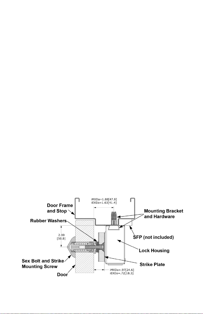
NOT E 2: Figure 2, “Typical S ecti on of Instal l at i on (iMXD a),” provides
ill ustrat i on for the following step.
1. VERIFY that the loc k hous ing w ill be mount ed to the header near the corner
oppo s ite t he door hinge side
Figure 2. Typical Section of Illustration (iMXDa)
7 500-22155, Rev B
Page 8
Mounting the Strike
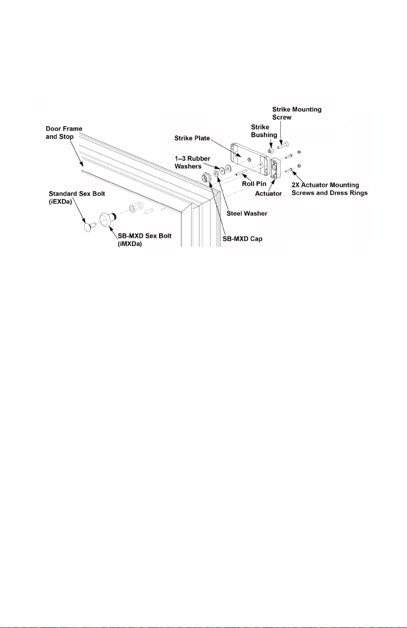
NOTE: Figure 3, “Typical Str ik e Mounting f or the iMXDa,” illustr at es t ypical
strike mounting f or the iMXDa. F or the iEXDa, the SB-MXD Sex Bolt,
cap, and steel washer sh own ar e r eplaced with a standard sex bolt .
Figure 3. Typical Strike Mounting for th e iMXDa
1. MO UNT the strike plate prior to t he loc k housing k eeping the f ollowing items
in consider ation:
• When installing t he str ike plate, the long edge of the strik e mu st be
at least 1/8" [3.2 mm] away from the door frame stop. T he installed
strike mu st allow the d oor to close properly.
• At least 3/4” [19mm] c learance mu st be pr ovided between t he end
of the lock and the cor ner of t he door fram e for tool acc ess.
• The entire mou nting area for t he loc k br ac k et and housing mu st be
a flat surfac e.
• When installing t he loc k in the vertical position it i s recommended
that the strik e be mo unted wit h the roll pin oriented t oward the t op.
• The external and int ernal are as of the marked door and f r ame
should be chec ked for any mount ing obstacles and necessary
adjustments sh ould be made to avoid the se o bstac les. The
provided te mplate for marking the mou nting locations of t he loc k
hou si ng mount ing br acket and strike should b e used.
• The installed lock (E-laminate) face and the strik e plate must be
alig ned so that t hey are cent er ed with each other.
a. Fully OPE N the door.
b. Carefully FO LD the t emplate and P LACE into the desir ed location.
c. On the door, CENTER P UNCH the strike and actuat or mo unting holes
mark ed [A] on the template.
8 500-22155, Rev B
Page 9

d. On the f r ame, CE NTER P UNCH the slott ed loc k mo unting holes marked
[A ] on t he template.
e. DRILL the 2 holes req uir ed for t he str ik e in t he door a s noted on the
template.
f. INS TALL the provided roll pin into t he back of the strik e plate u si ng a
hammer.
NOTE 1: Steps “g” through “o” are co mpl eted f or the installat ion of t he
iMXDa.
NOTE 2: T he S B -M XD may be used to mark the two (2) pin holes by
in sert ing the sex bolt into the hole f r om the outside of the door
and li ghtly tapping the head with a h ammer so that the pins mark
the door where the holes are to be located. The head should be
covered with a piece of cardboard to protect f r om marring, if
necessary.
g. MARK and DRILL t he two 3/ 16” [4. 8 mm] dia m eter holes for the pins of
the S B -M XD on the out sid e of t he door – these holes are designated [ C]
on the template.
h. INS TALL the sex bolt t hr ough the hole in t he door from the outside,
enga ging the pin s i nto t he holes.
i. THREAD the cap ont o the end of the sex bolt inside of t he door , and
TIG HTEN the asse mbly using a wrench.
NOTE: Use of two (2) r ubber washer s i s recommended in the fol lowing
step.
j. In the following order, ASSEMB LE the strike mounting screw, strike
bu shi ng, strike plate, 1 to 3 rubber washer(s), and the ste el washer.
k. APP LY thread loc k ing c ompound to t he str ik e screw threads.
l. THREAD the strike m ounting screw int o the sex bolt just a f ew t hr eads,
whil e aligning t he r oll pin int o the hole in t he door .
m. PULL on t he asse mbly (str ik e) to expose the end of the spri ng loaded
plunger.
n. With t he plunger being held extrac ted, TIGHTEN the asse mb ly using a
wrench ( or vise grip pliers) on t he plunger end and a 3/16” hex key
wrench in the sock et head of the screw.
o. RELEASE the assembly .
NOTE: St eps “p” through “u” ar e c ompl eted f or the installat ion of t he
iEXDa.
p. INSTALL the sex bolt through the hole in the door from the outside.
q. , ASSEMBLE, in the following order, the strike mounting screw, strike
bushing, strike plate and
9 500-22155, Rev B
rubber washer(s) together.
Page 10
r. APPLY thread locking compound to the strike mounting screw threads.
s. While holding the assembly together, THREAD the strike mounting
screw into the sex bolt just a few threads, while aligning the roll pin into
the hole in the door.
t. PULL on the assembly (strike) to align and engage the knurled potion of
the sex bolt into the
C AUTI ON: Over tig htening of the strike/ sex bo lt assembl y can cau se
damage to the ru bb er wash ers and may prevent proper operation or a
reduction in holding strength of the unit.
u. While keeping the assembly aligned, TAP the head of the sex bolt into
place using a hammer,
key wrench in the socket head of the screw.
hole.
and TIGHTEN the asse mbly using a 3/16” hex
Mounting the Actuator
1. DRILL the t wo ( 2) pr evious ly mark ed ac tuat or mo unting holes as noted on
the template.
2. INSTA LL the act uator to t he door usin g a #2 P hillips screwdr iver and the
prov ided screw s.
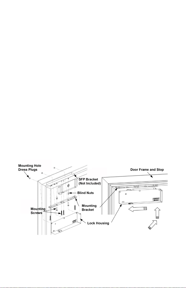
Mount ing the Lock Housing
NOTE 1: Figure 4, “Installing t he Lock Housing,” pr ovides ill ustr ation f or the
follow ing step s.
Figure 4. Installing the Lock Hous ing
NOTE 2: At least t wo ( 2) blind nut s (as specif ied by the t emp late) mu st be use d
for installing t he mou nting brac ket t o alumin um and/or hollow metal
frames.
10 500-22155, Rev B
Page 11

NOTE 3: Steps 1–3 are for a metal door fram e.
1. DRILL two 3/ 8” [9. 5 mm] diameter holes and one 1/2” [12. 7 mm] dia meter
hole at the three prev iously hole positions marked [A ] on the frame.
2. INS TALL two 1/4-20 blind nuts into the 3/8” diameter holes (see the s ec tion
for details of how t o install the bli nd nuts).
3. ATTA CH the lock mo unting brac k et t o the f r ame us ing a #3 Phillips
scre wdr iver and the two 1/ 4-20 UNC X 1” long machine screws,
NOTE: St eps 4 –5 are for a wood door frame.
4. DRILL two 3/ 16” [4. 8 mm] diameter holes X 1-1/4” [ 32 mm] deep (mi nimu m)
and on e 1/2” [12. 7 mm] diameter hole through t he fram e at t he pr eviously
mark ed [A] hole posit ions.
5. ATTA CH the lock mo unting brac k et t o the f r ame using a #3 Phillips
screwdriver and two #12 X 1-1/2” long Type “A” screws.
6. LOO SEN the two mount ing screw s enough to all ow movement of the brac ket.
7. ASS EMBLE the lock onto t he bracket .
a. SHI FT the unit to one side ( appr oximately 1-1/2”).
b. ENG AGE the t op of t he housin g onto t he br ac ket.
c. SLI DE the brac k et back toward center ( s ee Figure 4).
d. ENSURE the lock is cent er ed on the brack et.
8. ADJUS T t he loc k ( and br ac ket) into positi on, makin g contact wit h t he face of
the strike.
9. MARK the door frame at eac h end of the as s embly t o indic ate t he position of
the mo unting brac k et, and then carefully REM OVE the loc k from the br ac ket.
10. RE-A LIGN the brac k et to the position marks, as necessary.
11. TIGHTEN the two bracket mounting screws fully using a screwdriv er .
12. Using the mounted brac ket as a guide, CENT E R P UNCH the fr am e at the
four remain ing mounting holes marked [B] on the t emp late.
NOTE: St eps 1 3–14 are for a m etal door frame.
13. DRILL four 3/16” [4.8 mm] diamet er holes through t he frame.
14. SECURE the bracket to t he frame u sing a #3 P hillips scr ewdriv er and t he
four #12 X 1-1/2” long T ype A screws.
NOTE: Steps 15–16 are for a wood door frame.
15. DRILL four 7/32” [5.5 mm] diameter holes X 2-3/4” [70mm] deep (minimu m)
into the f r am e.
11 500-22155, Rev B
Page 12

16. SECURE the bracket to the f r ame using a #3 Phillips screwdriver and four
#14 X 3” long Type “A” screws.
17. AS S EMBLE the lock onto the mounting bracket.
18. TIGHTEN the three set screws along the upper/ bac k side of the unit to
secur e usi ng a 3/32” hex wr enc h.
19. CHECK lock mo unt assemb ly for adequate tightness and secure installat ion.
20. MA K E wir e c onnec tions, APPLY power , and TEST for pr oper operation.
21. Aft er c ompl eting wiring and testing, ENSURE that the t hr ee s et screws in the
top/rear of t he loc k housing are tight and the loc k is secure.
22. INSERT the provided dress pl ugs into the lock set scr ew and actuat or
mount ing holes.
Installing the Blind Nuts
NOT E: Figure 5, “Installi ng B l i nd Nuts,” provid es ill ustration t o t he
steps i n this section.
Figure 5. Installing Blind Nuts
1. INS TALL a blind nut into eac h of t he 3/8” [9. 5 mm] holes specif ied by the
temp late using the provided blin d nut collapsing tool.
a. INSERT t he as se m bled blind nut installatio n tool provided into a
mount ing hole.
b. HOLD the install nut using a 1/2” [13 m m] box or open en d wr ench.
c. TURN the soc k et cap screw and COLLAPS E the blind nut us ing a 3/16”
[5.0mm] hex wrenc h.
d. REMOVE the collapsing tool when f inished.
NOTE: The c ollapsing tool is reu s able for several blind nut installation s
e. VERIFY that t he blind nut is securely colla psed.
12 500-22155, Rev B
Page 13

R ep laci ng the Mort ise Cylinder and Cam
General
The m or tise cylinder and cam is f ield replac eable. The cylinder is ret ained by a
knurl-nut and bracket to ensur e pr oper alignment and provide ant i-rotational
support. The nut is remov able, and m ay be loos ened or tightened by using a flatbla de scr ewdr iv er .
Alternate Cy linders
Cylinders m ust be 1-1/8” [ 28.6mm] deep for proper alignment with the mode
selection switch. T he use of 1” [25. 4mm] or 1-1/4” [31.8m m] c ylinder is not
recommended. Figure 6, “Recommen ded Cylinder Dim ensions,” sp ec ifie s the
recommended dimens ions. I f a longer cy linder is u s ed, a spac er r ing must be
add ed for pr oper alignment.
Figure 6. Recommended Cylinder Dimensions
Alternate Cams
Various cam types will operate in the iMX Da/iEXDa. Cam dimen s ional referenc es
with mi nimu m/max im um variables are illustrated in Figure 7, “Cam Dim ensional
References.” Figure 8, “ Alternate Cams,” di s plays cams tested for use in the
iMXDa/iEXDa. The 13-00 97 Cam is fac tory inst alled. Other ca m s may be used.
13 500-22155, Rev B
Page 14

Figure 7. Cam Dimensional References
Figure 8. Alte rnate Cams
Installing the Electrical Connections
General Characteristics
The iMXDa/iEXDa is a low current device that uses specialized internal
circuitry to suppress inductive kick-back.
Electrical Standards
DC volt age, f ull-wave rectified, mu st be prov ided for proper oper ation of the
iMXDa/iEXDa. T he positive (+) terminal r eceiv es +12 VDC or +2 4 VDC, and t he
neg ative (-) ter mi nal, 0 Volt s. If the unit is connected wit h r ever se p olarity, it will
not operate. The iMXDa and iE XDa are a uto sensing dual voltage loc k systems.
Sensor Ranges (Electrical)
The internal bond monitoring sy stem of the Magnalock i s not only sen sitive to t he
proper physical position of the strik e, but also v oltage. P r oper voltage in t he
range spec ified must be applied.
14 500-22155, Rev B
Page 15

Electrical Wiring
All wiring to the installed unit is made to the main terminal strip on the PC board
inside the wire
access compartment.
Power Supply Connections
1. CONNE CT t he iMX Da/iEXDa to various Securitron power sup plies in
accor dance with F igure 9, “Connecting t o a 1-Amp Power Supply (BPS-12-1
or BPS-24-1) ,” Figure 10, “Connecting t o a 2–4.5 A mp (BPS) Pow er Su pply, ”
Figure 11, “Connecting to a 6–15 Amp (BPS) Pow er Supply ,” or Figure 12,
“Connecting t he iMX DaCH to a BP S -CH Power S upply.”
Figure 9. Connecting to a 1-Amp Power Supply
15 500-22155, Rev B
Page 16

Figure 10. Connecting to a 2–4.5 Amp (BPS) Power Supply
Figure 11. Connecting to a 6–15 Amp (BPS) Power Supply
16 500-22155, Rev B
Page 17

Figure 12. “Conne cting the iMXDaCH to a BPS-CH Power Supply.”
Emergency Release
Integrated exit delay Magnalock units are t ypically wired into the building f ir e
prot ec tive or sprinkler system. I t is recommend ed to use the f ir e alarm system
auxiliary relay to perf or m break of power. Sec ur itron power sup plies hav e
ter mi nals for interconnec tion t o such emer genc y relea s e s witches.
SYSTEM OPERATIONS
General Operat i ons Descri ption
The iM XDa uses a M 62 S er ies Magnalock to sec ur e an o pening. W hen there is
an att em pt t o exit, the S B -MXD sex bolt permits the door to mov e within a 1” limit
whil e r emai ning secure. The door movement distance (or gap) f or an alarm i s
set by “training” the unit ’s microproce s sor t o trigger at a desire d distance.
Whenever this programmed do or movement is detected, the unit initiates an
alarm, and during thi s alarm se quence, t her e is a release delay where the local
alarm ins ide the housing soun ds and a remote alarm co ntact act ivates. At the
end of the alarm se quence, t he loc k r eleases, the local alarm stops, but t he
ext er nal alarm contact rema ins act ive. T he unit remai ns in the r eleased state
until it is either ma nually or automatically r eloc k ed (re set) . Reset mu st be
accompl ishe d m anually by the momentary turn of the Integrated Reset/Bypass
(IRB) key switch or performed thr ough a remote input.
17 500-22155, Rev B
Page 18

Com p onent La yo ut
Figur e 12, “ General Layout and Position of the P C B oar d in the Wir e Access
Co mpartment ,” pr ovides illustration of the iMXDa/iEXDa for this secti on.
Figure 12. General Layout and Position of the
PC Board in th e Wire Access Compartment
Power On Res et
Power on r eset is a star t up f unc tion t hat is initiat ed whenever power i s ap plied to
the iM XDa unit. A t power up, t he iM XDa locking sy stem p er forms t he following
self diagnostics:
• Validat es program v er sio n
• Read s DIP switch sett in gs
• Verifies door position
• Confir m s lock statu s secur e
• Initiat es sta ndard oper ational mode
Integrat ed Res et/Bypa s s (IRB) Key Switch
The iM XDa/iEXDa incorporates a mort ise l oc k c ylinder an d c am that are
accessible f r om the bott om of the lock housi ng (see F igure 12). This Integr ated
Re set/Bypass (IRB) k ey swit c h is required for gap adjustment and activation of
the r es et and bypass func tions. T he furnishe d c ylinder i s replaceable wit h a
v ariety of commercial cylinder/cam comb ination s.
Standard Operational Mode
This iMXDa unit operat es i n this mode most of t he time. W hen the door is
closed, and t he m agnet is secure, the green LED is on.
18 500-22155, Rev B
Page 19

The gr een and red LE Ds provide visua l status. The functional unit LE D
indicat ions are as follows:
• Gr een LE D is on when t he door is closed and secure.
• Red LED is on when an alarm event has released the door and it i s
awaiting reset.
• Gr een and r ed LEDs are on when the sy stem i s in a n alarm sequence.
• Gr een and r ed LEDs are off if the lock is not powered or is in bypass
mode.
Bypass Mode — IRB (or Ext ernal)
Bypass mode allows a timed mo mentar y relea s e of t he door , and can be entered
via t he onboar d IRB k ey swit c h or an external sw itch. Using the onboard IRB key
swit c h pr ovides a fixed 15-second door r elease with aut omatic r eloc king. During
an alarm ev ent, bypass can be us ed for emergency ex it.
Reset — IRB (or External )
Re set r eloc ks t he door aft er an alarm event, and is accomplis hed by manually
tur ning the onboard IRB k ey swit c h c loc k wise. Reset can also be accomplished
using an external switch.
System Functions
General
The following is a general description of the iMXDa loc k system functions and
DIP switch settings. For DIP switc h loc ation see Figure 12. DIP switch setting
changes are recognized at t he microproc essor when:
• Power is ap plied to the loc k .
• During a bypass event (prior to t he door being close d) .
• After an alarm event (prior to res et).
Figur e 13, “F actory Default DIP Switch SW1–SW8 S ett ings,” Figure 14,
“Calif ornia DIP S witch SW1–SW 8 S ettings,” Figure 15, “ Chicago DIP S witch
SW1–SW8 Settings,” and Table 1, “ DIP S witch S ett ings Mat r ix,” pr ov ide a
complete illustration of DIP sw itch settings and their function s.
19 500-22155, Rev B
Page 20

Figure 13. Factory Default DIP Sw itch SW1–SW8 Settings
Factory
Settings
SW1
SW2
Seconds
OFF
OFF
0
√
ON
OFF 1
√ fixed
√ fixed
OFF
ON 2
ON
ON 3
Figure 14. California DIP Sw itch SW1–SW8 Settings
Figure 15. Chicago DIP Switch SW1–SW8 Settings
Table 1. DIP Sw itch Settings Matrix
Operat ion 8-Position DIP Dire ctive
~ NDA ~
Nuisance Delay
Alarm
20 500-22155, Rev B
Default
California
Settings
Chicago
Settings
Page 21

Operat ion 8-Position DIP Dire ctive
Factory
Settings
Cycle
Time
OFF
15
√
√ fixed
√ fixed
ON
30
SW4
SW5
Seconds
OFF
OFF
0
√
√
√ fixed
ON
OFF 5
OFF
ON
10
ON
ON
15
~ PAR ~
Reminder
SW6
Function
OFF
Disabled
√
√
√ fixed
ON
Enabled
~ BEA ~
Alarm
SW7
Function
OFF
Disabled
√
√
√ fixed
ON
Enabled
~ MDR ~
Relock
SW8
Function
OFF
Manual
√
√ fixed ON
Delayed
√ fixed
Default
California
Settings
Chicago
Settings
~ IRA ~
I rrevocable Alarm
~ BDT ~
Bypass Delay Time
(External Only)
Post Alarm
Bypass Expiration
Manual/Delayed
SW3
Nuisance Delay Alarm (NDA) — DIP Switches SW1 and SW2
NDA is a 0-, 1-, 2-, or 3-second nuisance or warning delay (revocable) that
initiates when door movement is detected. When t r iggered, t he loc al alarm
(pulsing tone) will sound. T he factory default setting is 0; sett ings are changed
using DI P switc h settings of SW1 and SW2. This setting is fixed to 1 second on
the California and Chicago ver sion s.
Irrevocable Alarm (IRA) — DIP Switch SW3
IRA is an irr evocable a larm that initiates when door movement is detected. Once
initiated, the com plete delay cyc le must expire prior to reset. This i s a set 15- or
30-second tot al alarm tim e c ycle. T he audible alarm sounds until t he IRA
expires. T he factory default setting is 15 seconds, but c an be changed to 30
seconds by changing DIP switch SW3. T his setting is fixed to 15 seconds on the
California and Chicago versions.
Bypass Delay Time (BDT) — DIP Switches SW4 and SW5
BDT is a bypass func tion only. Onc e trigger ed, a set 0-, 5-, 10- or 15-second
release time is initiated. The f ac tory default setting is 0, but c an be set to 5, 10 or
15 seconds (tr ailing edge t r igger ) by chang ing DIP switc hes SW4 and S W5. This
setting is fixed to 0 seconds on the Chicago v er s ion.
21 500-22155, Rev B
Page 22

Post Alarm Reminder (PAR) — DIP Switch SW6
PAR is an aud ible alarm i ndicating t he loc k has co mpl eted an alarm cycle. Aft er
5 seconds, the int ernal alarm will rapidly beep 3 times, f ollowed by 5 seconds of
silence, and wi ll then repeat until r eset. T he factory default setting is off
can be t ur ned on with DI P switc h S W6. This setting is disabled on the Chicago
version.
, but PAR
Bypa s s Expiration Alarm (BEA) — DIP Switch SW7
The bypass expir ation alarm i s an a udible, rapid, 4-beep signal that r epeat s thr ee
(3) times over a 5-second t ime period. This indicates that the bypass t ime period
ha s expired and the door must be c losed; if not, the lock will go into al arm mode.
The factory default setting is off
SW7. This set ting is fixed to 0 seconds o n the Chicago ver s ion.
, but t his func tion can be turned on via DIP switc h
Manual/Delayed Relock (MDR) — DIP Sw i tch SW8
The ma nual/del ayed relock allows either m anual reloc k or delayed ( 30-second)
automatic r elock. The f ac tory default setting is ma nual relock
changed wit h DIP switc h S W8. Delayed relock is fixed in the on
Chicago version. Delayed rel oc k is d isab led on the Cal ifornia ver sio n.
, but t his can be
position on t he
Alarms
Internal (Local) Alarm
The internal alarm of the iMXDa/iEX Da loc k system con s ists of an 85–100 dB
elect r onic (Piezo) sounder. T his aud ible alarm func tions dur ing alarm cycles,
po st alarm remi nders and bypass egress time expiratio n.
External (Remote) Alarm
The external alarm f or the iMXDa/iEX Da c onsi sts of an integrated SP DT [ s ingle
pull d ouble throw] dr y contac t wit h c onnec tion point s marked “C”, “ NO ” and “ NC” .
At the initiat ion of an alarm sequ enc e, or at t he loss of power, t he r elay deenergizes to pr ovide a sig nal to an alarm or monitoring sy stem.
Control Wiring
W iring Layout
Figur es 16, “General Cont r ol B oar d Diagram,” Figure 17, “ Opt ional Ex ternal
Contr ol Connections,” and Figure 18, “ S electable O utput J um per P ositions,”
provide illustration f or this sect ion.
22 500-22155, Rev B
Page 23

Figure 16. Gen eral Control Board Diagra m
23 500-22155, Rev B
Page 24

Figure 17. Optional External Control Connections
Figure 18. Selectable Output Jumpe r Positions
24 500-22155, Rev B
Page 25

External Controls
The unit has termin als that provide the necessary connections for r emote c ontrol
of specif ic functions. F igur e 16 sh ows examples of the f ollowing connections:
• The “ RS ” termi nal prov ides a connection f or r emote r eset.
• The “BP” terminal provides a connection for remote bypass.
• The “ E I” termina l pr ovides a connection f or external initiate of exit delay.
To oper ate t he external initiate ( iE XDa), the JP 3 jum per , which by
fac tory default is placed over pins 2 and 3, mu st be r emoved and placed
over pins 1 a nd 2 (see F igure 17).
• The “ RF” termin al is a commo n r eferenc e ( +) voltage sup ply point t hat
may be used for the above described external controls.
External Initiat e (iEXDa)
External init iate is nor m ally used to pr ovide access u si ng an exit device rather
than door movement. The rem ote mak e-to-break device i s wired t o pr ovide a
signal t hat t r iggers t he loc k to release. All lock func tion DI P sw it c h s ettings
remain intact . T he ac tuat or mu st be installed for activation of the door movement
(gap) sensor . T he sen s or is u sed to m onitor door pos ition f or post alarm, bypass
reminder, and relock func tions.
Tamp er Status (JP1) a n d Door Status (JP2 ) wiring
The Tamper S tat us func tion can only be oper ated in units equipped wit h an
XDAT-KIT. This kit is so ld separately and includes a n alternate lock housing end
cap, and imp leme nts a micro switch which supp lies a si gnal when t he front cover
of the housing is accessed. The installation and operating instruction s included
with the kit det ail proper i nstallation.
The tamper status and door st atus switc hes provide dry contac t out put at the
ter mi nal block he ader . O utput is field selectable via the jumpers shown in Figure
18. The factory default jumper sett ings for both JP 1 and JP2 are set f or normally
closed
operation (pins 2 and 3). If nor mal ly open operat ion is d esired, c hange
the jumper sett ing to pin s 1 and 2.
Wire Gauge and Length
General
The iM XDa/iEXDa requires adequate voltage a nd c ur r ent for pr oper operation;
both of which c an be affec ted by resistance. Resistance is created by the length
and ga uge (size) of t he wir e being used. T he following f ac tors nee d to be
consider ed in determining proper w ir e length an d gauge:
• An acc ur ate estimated distance from the power sup ply to t he opening is
crucial.
25 500-22155, Rev B
Page 26

• For optimum operat ion, t he c or r ec t size gauge wir e mu st be use d.
Devices Used
Cur rent D raw (Amps)
Running Total (Amps)
iMX Da
0.370
0.370
DK-26 Access
0.160
0.530
MK Bypass/Reset
0.020
0.550
Total Current (Rounded Up to Nearest Tenth)
0.600
Devices Used
Cur rent D raw (Amps)
R unnin g Total (A mp s)
iEXDa
0.270
0.270
TSB Touch Bar
0.025
0.295
DK-11 Access
0.070
0.365
Total Current (Rounded Up to Nearest Tenth)
0.400
• The devices being used oper ate best wit h the least amount of
resistanc e on the sourc e.
• Using t he c or rect gauge wires prot ec ts against large voltage and cur r ent
(load) losses.
• The gauge is determined by the wire distance, voltage, and cur r ent of all
devices.
Det ermining Wire Gauge and Length
NOTE: Table 2, “12 VDC System Wire Gauge and Lengt h,” and Table 3, “ 24
VDC Sy stem Wir e Gauge and Lengt h,” pr ovide the proper system
wire gauge and lengt h base d on c ur r ent draw.
1. DET E RMINE pr oper wir e gauge and lengt h by following Example A for a 12
VDC sy stem a nd E xample B for a 24 VDC system, and using Tables 2 and
3.
Examp le A: iMXDa use d in a 12 VDC System;
200 feet of wir e needed one-way
Using T able 2 and int ersecting t he tot al c ur r ent draw of 0.600A and the required
wire length of 200’, a wire gauge of 18 is required.
Examp le B: iEXDa use d in a 24 VDC System;
200 feet of wir e needed one-way
Using T able 3 and int ersecting t he tot al c ur r ent draw of 0.400A and the required
wire lengt h of 200’, a wir e gauge of 18 i s required.
26 500-22155, Rev B
Page 27

Table 2. 12 VDC System Wire Gauge and Length
Current
Wire G auge
1.000A
20
18
16
14
14
12
10
10
8
0.800A
22
18
18
16
14
12
10
10 8 0.600A
22
20
18
18
16
14
14
12
10
0.400A
22
22
20
18
18
16
14
14
12
0.300A
24
22
22
20
18
18
16
14
14
0.200A
24
22
22
22
20
18
18
16
14
50’
100’
150’
200’
300’
400’
500’
750’
1000’
Wire Distance
Current
Wire G auge
1.000A
22
20
20
18
16
14
14
12
10
0.800A
22
22
20
18
18
16
14
14
12
0.600A
24
22
22
20
18
18
16
14
14
0.400A
24
22
22
22
20
18
18
16
14
0.300A
24
24
22
22
22
20
20
18
16
0.200A
24
24
24
22
22
22
20
20
18
50’
[15m]
100’
[30m]
150’
[46m]
200’
[61m]
300’
[91m]
400’
[122m]
500’
[152m]
750’
[229m]
1000’
[305m]
Wire Distance
[15m]
[30m]
[46m]
[61m]
[91m]
[122m]
[152m]
[229m]
[305m]
Table 3. 24 VDC System Wire Gauge and Length
A djusting th e Gap (iMXDa only)
NOTE: The iM XDa may be “trained” to t r igger at any desire d gap distance
between 1/8” and 1”. T he Chic ago ver si on is li m ited t o a 1/8” gap.
1. To ac c es s the gap adjustment mode, ENSURE that the door is at r est in the
closed position.
NOTE 1: T he sw itch m ust be ac tuat ed three (3) c onsecutive times within a five
(5) second period.
• The first s witch ac tuat ion will cause both LEDs to go off .
• The second switch ac tuat ion will cause the r ed LED to blink on and off
once.
• After the t hir d switc h ac t uation, the green and red LE Ds wi ll alt ernate on
and off f or one ( 1) s ec ond, and then the red LED will r emai n on.
NOTE 2: F ollowing thi s step, t he iMX Da unit has rea d and stor ed the closed
po sition of the door .
2. INSERT t he k ey into t he IRB cylinder and ROTATE clockwise to actuate t he
mode selec tion swit ch.
27 500-22155, Rev B
Page 28

NOTE 1: F ollowing thi s step, t he r ed LE D will be off and the gr een LED will be
on
.
NOTE 2: T he door movement (gap) distance is no w s et.
3. OPEN t he door to t he desired (gap) distance, and t hen TURN t he k ey
clockwi se once.
4. CLOSE the door and the unit is adj usted and ready for operation.
Installing the EXD-1L La bel
NOTE: Each iMXDa and iEXDa comes with an EXD-1L exit delay door
label as required by fire code.
1. FOLLO W t he inc luded application instruc tions to apply the lettering to a
door.
Sp eci al iz ed Mo unt in g Br ac ket s
The S top F iller P late (S F P ) br ac k et is designed to fill the stop rabbit and extend
the flat mou nting surface of t he frame he ad. Available thicknes se s are; 1/4”
[6.4mm], 3/8” [9.5mm], 1/2” [12.7mm], and 5/8” [15.9mm]. Length available f or
the iM XDa is 12” [305mm].
Operational Information
State of California – iMXDa-CA
This a ddr esse s the operating not ification s sp ec ifically r elated t o c ompl iance with
the state of California building codes 2 011 update.
St ate of California approved Delay ed E gr ess devices sha ll c onform to all of the
following:
1. The doors unlock upon actuat ion of the automatic spri nk ler or smoke
detec tion sy st em.
2. The doors unlock upon loss of elec trical power to anyone of the following:
a) The egress sy stem itself
b) The smoke det ec tion sy stem
3. The door sha ll have the capability of being unlocke d by a signal fro m a
swit c h loc ated in an approved area.
28 500-22155, Rev B
Page 29

4. A sign shal l be pr ovided on the door located above and with in 12 inches(25
mm) of the releasing device readi ng (KEEP PUSHING. THIS DOOR WILL
OPEN IN 15 [30] SECONDS. ALA RM WI LL SOUND.) Sign lett ering shall
be at least 1 inc h ( 25 mm) in height and sha ll have a st r oke of not less than
1/8 inc h ( 3.2 mm).
5. Actuat ion of t he panic bar or other door latching hardware shal l ac tivate an
audi ble si gnal at the door .
6. Regardless of the means of deac tivation, the reloc k ing of the egr ess control
device sh all be by manu al mean s o nly at t he door .
City of Chicago – iMXDa-CH
This a ddr esse s the operating not ification s sp ec if ic ally r elated to co mpl iance with
the City of Chicago and related Municipal Codes.
For compliance with Section 13-160-269(a)( 7) of t he Mun icipal Co d e:
• The S ec ur itron – Model iM XDa-CH Int egr ated Movement E xit Delay
System wi ll c ontain no selec table operating mo des for the logic timers
or spec ialized alarm reminder oper ations.
• The timing system is fixed with a 1 seco nd initiating time (nuisance
time d alarm) plus a 14-s ec ond (Irr evocable tim ed alarm) sequence and
delayed lock r elease and egres s i mpl ementation.
• Aut omatic r e-loc king only occurs if the door opens and r eturns to the
closed position and the n r em ains closed for a full 30 sec ond period
thereafter.
For compliance with Section 13-160-269(a)( 1) of t he Mun icipal Co d e:
• The S ec ur itron – Model iMXDa-CH Integr ated Movement E xit Delay
System mu st be use d with a UL listed f ir e alarm sy stem.
• The fire alarm sy stem must contain lat c hing type dry c ontacts
de sig nated f or “ auxiliar y” operat ions.
• The c ontacts mu st ac tivate for both t he alarm and t r oubled conditions.
For compliance with Section 13-160-269(a) of t he Municip al Code:
• The S ec ur itron – Model iM XDa-CH Int egr ated Movement E xit Delay
System mu st be use d with a Sec ur itron ~ M odel B P S -CH Series Po wer
Supply.
• The power su pply unit is to be supplied wit hout provisio ns for batt er y
back-up.
29 500-22155, Rev B
Page 30

Door Travel Limitations and/or Restrictions:
• The S ec ur itron – Model iM XDa-CH Int egr ated Exit Movement Delay
System mu st be c onfigured to tr igger the egress init iating wit hin oneeighth inch (1/8” ) of door movement.
• The max imu m do or travel is limited t o a one-half inch (1/2”) movement
measure d at t he str ik e armatur e/sex bolt mounting location.
MAGNALOCK MAINTENANCE
Pe rfo rmi ng an I nspe ct io n
1. CHECK the rubber was hers f or elastic ity and proper pivoting; and TI GHT E N,
as required.
2. CHECK for build-up of debr is o n the magnet face an d str ike ar matur e, and
CLEAN, as requir ed.
3. CHECK for r ust on the magnet and strike plate armature; and CLEAN, as
required.
4. CHECK for ir on debris o n the actuat or and str ik e ( DP S ) magnet ic housings;
and REMOVE, as required.
NOTE 1: Cleaning once a year i s recommended.
NOTE 2: Cleaning every six months is recommend ed wh ere minor ru st ing
occurs.
NOTE 3: Cleaning every three mo nths is recommended if ru sting conditions
are severe.
Cle aning th e Mag n alo ck
1. APPLY rubbing alcohol onto a clean cloth and thor oughly WIPE DO WN the
Magnalock and str ike plate armature.
2. USE a pla stic dishwas hing scrub pad to ai d in the removal of r ust.
TROUBLESHOOTING
No alarm when testing door movement
1. CHECK for s pec ified voltage to the unit.
2. CHECK for s pec ified cur r ent draw at the unit .
30 500-22155, Rev B
Page 31

3. CHECK the mag netic actuat or for proper m ounting.
4. ENSURE gap testi ng and training of unit.
Immedi at e alarm when test in g mo vement
1. CHECK for pr oper door closure.
2. CHECK mag netic ac tuat or for pr oper mounting.
3. Check loc k housing and str ike for pr oper mou nting.
4. ENSURE Ju mper JP3 is in the correct po sition.
5. ENSURE that the cir c uit connected t o the “E I” termin al is properly
func tioning. ( iE XDa only )
6. ENSURE gap testi ng and training of unit. ( iM XDa only)
Lock does not gen erat e a magnetic f ield
1. See Reduced Holding F or c e sect ion.
Magnalock has reduced holding force
1. CHECK for s pec ified voltage at Magnalock.
2. CHECK for s pec ified cur r ent draw at Magnalock.
3. CHECK the strik e for pr oper mounting.
4. CHECK Magnaloc k and str ik e for obstructions.
5. ENSURE that Magnalock and strik e ar e pr operly c leaned.
DPS does not report door status
1. CHECK str ik e mou nting f or pr oper alignme nt.
2. CHECK for pr oper door closure.
3. CHECK for pr oper v oltage/ c ur r ent on t he switc h.
4. CHECK r esettable protection (polyswitc h overloa d) .
The Magnalock is dirty or rusty
1. ENSURE Magnaloc k is clean.
El ect ron ic noise int erf erence wit h Access Co ntrol Sy stem
1. CHECK for voltage f r om Magnalock to door frame to ensure t her e is no
volt age pr esent.
31 500-22155, Rev B
Page 32

© 2015, Ha nc he tt Entry Sy s t e m s, Inc., an A SSA AB LOY Gr oup C ompany .
Securitron
securitron.com
10027 S. 51st St. St e 102
Phoenix, AZ 85044
Tel: 1-800-624-5625
Mon-Fri: 6:00am - 4:00pm PDT
Fax: 1-800-232-7329
32 500-22155, Rev B
 Loading...