

Page 1
Securitron Magnalock Corp. www.securitron.com
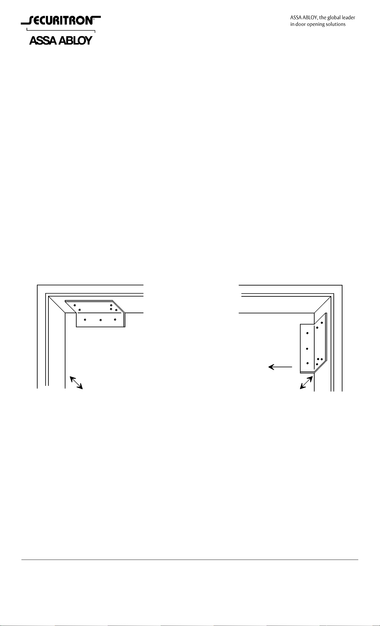
DOOR
FRAME
HEADER
DOOR
FRAME
HEADER
PLACEMENT OF DRILL
GUIDE FOR HORIZONTAL
LOCK MOUNTING
PLACEMENT OF DRILL
GUIDE FOR VERTICAL
LOCK MOUNTING
SLIDING THE GUIDE IN THESE
DIRECTIONS COMPENSATES FOR
MAGNET MOUNTING SCREWS
ALIGNING WITH FRAME STOP EDGE
SLIDING THE GUIDE IN THESE
DIRECTIONS COMPENSATES FOR
MAGNET MOUNTING SCREWS
ALIGNING WITH FRAME STOP EDGE
THE GUIDE MUST BE SLID 1/10"
IN THIS DIRECTION
WHEN THE LOCK IS MOUNTED
VERTICALLY
Tel 800.624.5625 techsupport@securitron.com
MODEL IK, IKM INSTALLATION TOOL KIT
INSTRUCTIONS FOR USE
1. DESCRIPTION
The IK contains tools that will improve the speed and quality of model 62 and 32 Magnalock
installations. It also includes additional fasteners and a Tips and Techniques Installation Video.
The IKM is the export version which includes metric fasteners.
2. DRILL GUIDE
The drill guide is the gold colored angle piece. This allows drilling more rapid and accurate pilot
holes for mounting the magnet and strike plate on outswinging doors. It replaces the paper
template provided with the lock. The holes in the guide are sized for use with a 1/8" drill bit and
the guide includes hardened steel bushings so that it will last for many Magnalock installations.
2.1 POSITIONING THE GUIDE
The first point to notice about the guide is that it has two sets of holes: for the 62 and 32
Magnalock. The six 32 Magnalock holes are surrounded by a silver colored ring. The eight 62
holes are "plain". Next, the guide must be placed against the door and frame (with the door
closed). Figure 1 shows the concept of positioning the drill guide for horizontal and vertical
mounting. Note that the 3 "in line" holes are always for the strike plate and it is this set of holes
that must be positioned on the door. Note also that in the drawing, the guide has been moved
in from the corner somewhat. This is to permit easy drilling of the holes nearest the corner.
This distance that the guide should be moved in from the corner will depend on the type of drill
you will be using. You can set this distance by simply positioning the drill against the frame.
FIG. 1: POSITIONING THE DRILL GUIDE FOR HORIZONTAL AND VERTICAL MOUNTING
The drawing shows an "ideal" door frame because the door stop is wide enough to fully mount
the magnet body. This will not always be the case and you should be prepared to employ
accessory brackets. See the Magnalock instruction manual for descriptions of these brackets.
One problem that brackets cannot solve is if the mounting screws of the magnet body fall on an
edge in the frame or stop. This can be compensated for by varying the number of rubber
washers that stand off the strike plate from the door. The stand off that is set by positioning the
drill guide as shown in Figure 1 is 1/4" (6MM) which is the thickness of two rubber washers.
Magnalocks are delivered with three rubber washers and extras are supplied with the kit so you
can slide the guide farther away from the door and compensate with extra rubber washers. You
can also drop down to one rubber washer by moving the guide 1/8" (3MM) closer to the door.
To accomplish this, obviously the door must be opened slightly. Note also that when you're
using the model 62, it is possible to mount the product with only two magnet mounting screws
(at opposite ends of the magnet). This is not ideal as it sacrifices some rigidity, but two screws
mounted into blind nuts are of adequate strength.
© Copyright, 2011, all rights reserved PN# 500-11900
Page 1 Rev. C, 07/11
Page 2

Above we've discussed a reason for sliding the guide towards and away from the door. For
BLIND NUT THUMB TURN
STROKE LIMIT THUMB TURN
FRAME
BLIND NUT
STOP RING
vertical mounting, the guide must be slid parallel to the door to move the top of the strike a
little farther away from the top of the magnet. The guide sets this spacing at 1/10" (2.5MM)
which is appropriate for a horizontal mount. This spacing insures that the top of the strike will
not scrape against the door frame header. If the magnet is to be mounted vertically as shown in
Figure 1, the guide must be slid away 1/10" (2.5MM) parallel to the door so that the strike top
will now be 2/10" (5MM) away from the top of the magnet. The reason for this is that with a
vertical mount, the door closes on an arc and since the strike stands out from the door, it will
scrape against the frame stop unless this extra separation is achieved.
2.2 DRILLING THE HOLES
When drilling the holes it is important to realize that the only critical holes are the magnet
mounting holes. The strike mounting holes include two roll pins that fit very loosely in their
holes. Therefore be most careful when you are drilling the magnet mounting holes (two in the
case of the model 32; four in the case of the model 62).
If no sliding of the guide is necessary as described above, all of the holes may be drilled at once.
A 1/8" drill bit (furnished) is needed and an excellent technique is to begin with the central strike
mounting screw hole which should be drilled completely through the door. Then place a second
1/8" drill bit (or rod) into this hole to stabilize the guide for the drilling of the other holes. All
other holes do not go through the door but should be drilled to a depth of roughly 1 1/4"
(32MM).
If the guide must be slid, only one of its surfaces will be against the door/frame at a time.
Therefore the drilling of the strike and magnet mounting holes must be split into two different
operations. The guide is slid and the holes are drilled for the repositioned magnet or strike. It is
then slid back to drill the holes for the remaining component.
Once the 1/8" pilot holes are drilled, they should be enlarged to 3/8" or 1/2" depending on the
hole type. Drill bits of these two sizes are furnished and the paper template delivered with the
Magnalock shows the required hole sizes. For best accuracy on the critical magnet mounting
holes, use an intermediate 5/16" drilling step.
Note that the furnished drill bits are of different types which have been selected for optimum
performance. Understanding the drill bit types is helpful when they require replacement. The
gold colored 1/8” and 3/8” bits are cobalt which is a strong and long lasting drill bit type
particularly good in steel and aluminum. A second 3/8” bit is gray in color and is carbide for
drilling into concrete filled headers. The 1/2” bit is a high speed steel bit which is less durable
but it is extra long so it is easy to keep straight when you drill through the door. The 1/2” drill is
used only for one hole and is not readily available in cobalt with the extra length.
3. BLIND NUT COLLAPSING TOOL
The second important tool in the kit
is the blind nut collapsing tool (see
drawing to the right). This tool
allows faster installation of the blind
nuts than does the small tool
furnished with each Magnalock. To
use this tool, first free the handles
by removing the bent metal wrench
that holds them together. The
wrench is used for replacing the
threaded stud which carries the
blind nut and as Magnalocks only
use one thread pitch, the wrench is
not needed. Note however that the
stop ring does unscrew for removal (this is part of the procedure of changing the threaded stud).
It can easily become loose. You turn it counterclockwise to tighten it and clockwise to remove it.
Next note that the stroke limit thumb turn and connecting shaft is present to stop the handles
from coming too close when you squeeze the tool and therefore injuring your fingers. It
requires no adjustment. Make sure that the handles open and close easily and then thread a
PN# 500-11900
Page 2 Rev. C, 07/11
Page 3

blind nut onto the threaded stud with the flange facing the tool and the beveled end facing the
frame. How far down the stud, the nut will go depends on how much you allow the handles to
open. Open them about 1/3 of their maximum and thread the blind nut down on the stud
so that it bottoms. You don’t want to thread the nut farther (by fully allowing the handles to
open) as it becomes too difficult to collapse the nut within the frame. Then push the tool with
threaded blind nut up into the 3/8” (9.5MM) hole which has been prepared. Make sure you have
it positioned straight and squeeze the handles hard. You will be able to feel the nut collapse
inside the frame but it may not have collapsed completely as you did not squeeze the handles
for a long distance. Back off on the blind nut thumb turn several turns (while slackening
pressure on the handles) and this will give you an opportunity to squeeze again. It’s a rachet
effect. When you can no longer squeeze the handles, the nut is fully collapsed. Remove the tool
from the collapsed nut by turning the blind nut thumb turn counterclockwise so as to remove
the threaded stud from the nut.
With the nuts having been collapsed, the rest of the installation proceeds as is described in the
Magnalock manual.
4. ADDITIONAL TOOLS/PARTS
The kit also contains a T handle allen wrench of the correct size for tightening Magnalock
mounting screws and the strike mounting screw. The other items are additional fasteners to the
ones supplied with the Magnalock (in case of misplacement), and other useful fastener type
items which are sometimes needed when the Magnalock is to be mounted in an unusual
situation. "Refills" for all of these items are available from Securitron (see factory catalog).
5. RECOMMENDED TOOLS NOT IN THE INSTALLATION KIT
The following tools are not included in kit for reasons of wide availability and/or cost but we
recommend that you employ them.
A battery operated drill is the most productive way to drill your holes and rapidly install your
mounting screws. The absence of a power cord enhances safety as the risk of someone tripping
is lessened and in new construction, it can be awkward to bring AC power to the door.
A spring loaded center punch marks your holes for drilling quickly and accurately and reduces
the risk of the drill bit “walking”.
Bullet Point drill bits (Black and Decker) are widely available at Home Depot stores and other
outlets. They are costly but include a small diameter pilot bit in the center of the finished
diameter (3/8” or 1/2”) bit. This allows faster work as no separate pilot hole need be drilled but
more importantly, bullet point bits yield a rounder hole with reduced burrs which works better
with Securitron blind nuts. We urge you to try these bits and expect that you will find broad use
for them.
PN# 500-11900
Page 3 Rev. C, 07/11
 Loading...