

Page 1

Securitron Magnalock Corp. Tel 775.355.5625
© Copyright, 2009, all rights reserved PN# 500-12300
Page 1 Rev. C, 6/09
ASSA ABLOY, the global leader
in door opening solutions
SECURITRON MODEL DK-16W DIGITAL KEYPAD
INSTALLATION & OPERATING INSTRUCTIONS
1. DESCRIPTION
Securitron's DK-16W is a two piece digital keypad system designed to output Weigand 2601
format data and therefore integrate into an access control system just as if it was a card
reader. It consists of two components: the keypad and the CPU board. The keypad is for indoor
use only and installs in a single gang cut-out. It includes two active LED’s (green and red
controlled by the system) and a beeper.
2. PHYSICAL INSTALLATION
Two wallboxes are supplied with the DK-16W pad. The backless wallbox is used for flush
mounting on dry wall or other material where a cut-out can be made. The two-piece wallbox
allows surface mounting on a variety of materials. To use the two piece wallbox, note that its
cover and base are snapped together and must first be separated by either pulling the outer rim
of the cover away from the base or inserting a screwdriver into the four holes at the corners of
the cover and prying the base loose. Once the base is separated from the cover, remove the
large rectangular knockout in the center of the base by cutting around it with a knife and then
popping it out. The base can then be mounted with the supplied #6 sheet metal screws and
plastic anchors. The DK-16W pad mounts on the cover with the supplied #6 machine screws
(tamper or standard are supplied) and the assembly then snaps into the mounted base. Wires
are usually pulled through the center of the base although it is also possible to attach plastic
wiremold raceway to the side of the cover (note the knockouts on the inside of the cover sides).
Raceway is not recommended because it’s quite easy for anyone to attack the wires.
The DK-16W pad can be used outdoors with the optional rain cover (part #WCC) although we do
not advise this use in areas exposed to heavy, direct rain. When used outdoors, you must
supply a weatherproof, gasketed wallbox (available from Securitron under part #WBB).
The CPU Board is furnished in a snap-apart steel enclosure with the board itself mounted on
plastic snap-trak. The CPU Board must be installed in a dry location free of extremes of
temperature and humidity. If the 16 ft., twelve conductor cable that is included is not of
sufficient length, additional cabling can be spliced by the installer. However, a long cable run
can give rise to electronic noise problems in certain environments. It should therefore be
avoided where possible and in no case should cable length exceed 30 ft. (10 meters).
Cable entry to the CPU board enclosure can be handled in one of two ways. There is a hole in
the bottom of the enclosure, the use of which creates the most attractive installation as the
cable is completely hidden. Alternately, there is a side knockout in the enclosure cover which
permits surface mounting of the cable. The side knockout also permits a wiring technique
which is convenient when the CPU board enclosure is to be mounted in an awkward
location such as above a drop ceiling. You can pop the board itself out of its snap track and
make all your connections with the board in your hands. The board is then re-snapped into the
plastic trak. The enclosure cover snaps on with the wires emerging from the side kno ckout. If
you use this technique, avoid touching the components or rear pins on the board as
much as possible. Static electricity can destroy the processor. Also when you snap the
board back in its track, make sure it’s securely done. Sometimes you need to squeeze the
outer lips of the track to insure that the board edges are really seated in the slot.
Page 2
PN# 500-12300
Page 2 Rev. C, 6/09
BLUE
RED
3. WIRING
3.1 POWER, DATA AND KEYPAD WIRING
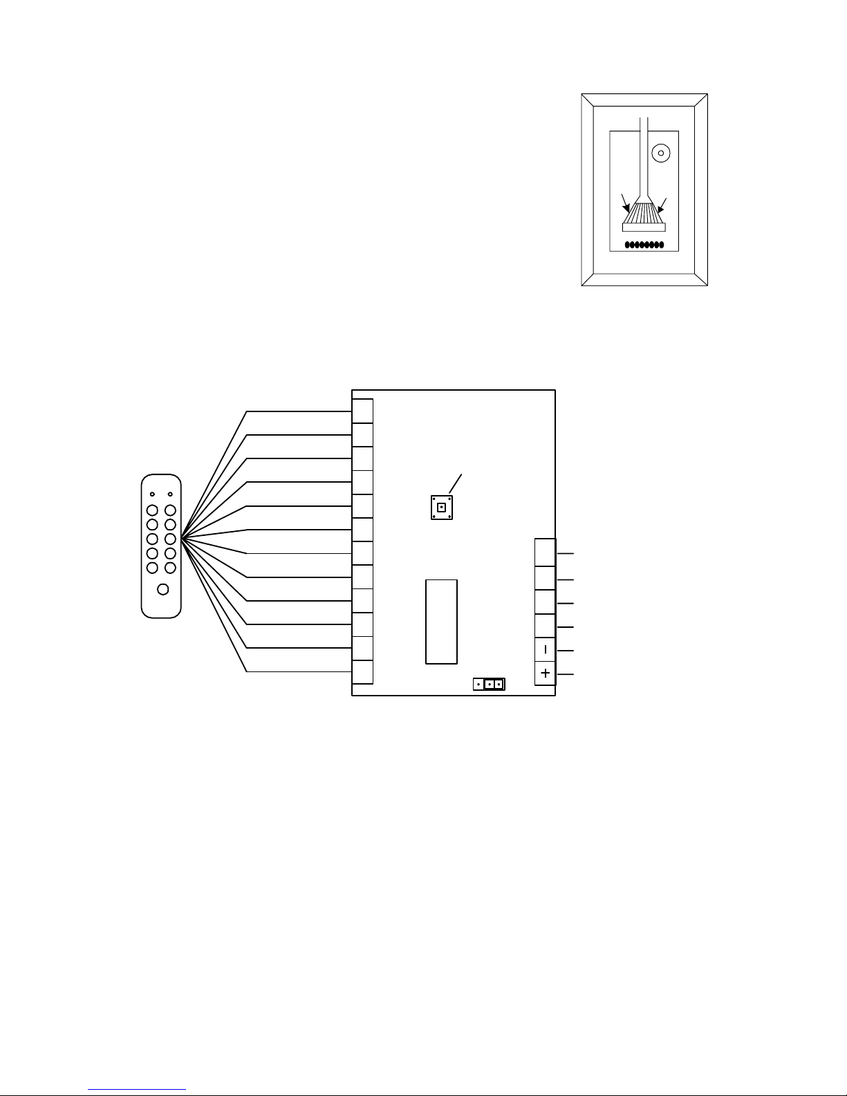
Note that the cable connector plugs into the rear of the circuit board
which is on the opposite side of the keypad. It is possible to plug the
cable connector incorrectly, so follow the drawing to the right for corre ct
orientation. Also, be careful not to pull on the cable as you route it
towards the CPU board or you could pull the connector out.
Figure 1 shows the DK-16W CPU Board. You will make connections to
the 18 terminals as shown in the drawing and either leave the jumper
block in the factory set position (connects pins 2 and 3) if you plan to
power the DK-16W with 12 VDC or move the jumper to connect pins 1
and 2 if you will be using 5 VDC. Note that operation at 12 volts with
the jumper block in the 5 volt position can damage the unit.
Note that the DK-16W will not operate on AC power. It will, however, accept full wave
rectified DC power (transformer + bridge rectifier) when it is being powered by 12 VDC.
When it is being powered by 5 VDC, the voltage must be regulated (+/- 1/2 volt). Be sure
to observe polarity when you power the DK-16W.
FIG. 1: OVERVIEW OF CPU BOARD
GRN YEL RED
BLU
WHT
BLK
GRY
BRN
BGE
ORG PNK VIO
D0 D1 LED XMIT
GREEN
YELLOW
RED
BLUE
WHITE
BLACK
GRAY
BROWN
BEIGE
ORANGE
PINK
VIOLET
MICRO-
PROCESSOR
FACILITY CODE
PROGRAM
BUTTON
TRANSMIT DATA
LED (FROM SYSTEM)
DATA 1
0 VDC (NEG)
+5 OR +12 VDC
DATA 0
132
JUMPER TO SET
VOLTAGE
FACTORY SET 2/3 = 12 V
CHANGE TO 1/2 FOR 5 V
There are 12 color coded wires in the keypad cable. Refer to Figure 1 an d connect each wire to
the indicated terminal on the CPU Board. No other connections may be made to these terminals
(except if two keypads are used with one CPU board).
The DK-16W will draw a maximum of 30 mA at 5 VDC or 12 VDC.
The Weigand output terminals: Data 0 and Data 1 connect to the appropriate inputs of the
access control system. The wire run maximum distance for reliable operation depends on the
wire gauge. A guide line is 200 ft. for 22 gauge; 300 ft. for 20 gauge and 500 ft. for 18 gauge.
3.2 LED AND “TRANSMIT DATA” WIRING
The LED’s on the DK-16W follow the convention for card readers. When a “high” signal (+5
VDC) is connected to the LED terminal, the red LED will be on and the green LED will be off.
Page 3

PN# 500-12300
Page 3 Rev. C, 6/09
When this input goes “low” (0 VDC), the green LED will be on and the red LED will be off. Th is
flipping of the LED’s is controlled by the access system and typically prompts the user when his
entry has been accepted (or not accepted). Note that the yellow LED is not used. It is there
because Securitron furnishes the same keypad for connection to different CPU’s which do
operate the yellow LED.
The “transmit data” terminal is not used with most systems. When it is unconnected, the code
sequence is automatically transmitted to the system following key entry (see Section 5).
However, with some systems, the controller can be busy and must therefore remotely command
data transmission. If this input is in a low state (connected to 0 VDC), the DK-16W will store
the code sequence until the input goes high (receives +5 VDC). The code will then be
transmitted as the system will be prepared to receive the sequence and release the door.
Naturally, while a code is being stored, the keypad will ignore further inputs as the delay prior to
the system commanding transmission of the code sequence will be very brief.
4. FACILITY (SITE) CODE PROGRAMMING
In the Weigand 16 bit code format (also called 2601), the first eight active bits constitute a
facility or site code. These eight bits correspond to standard numbers 0-254. The access control
system normally expects to see a “two part” transmission wherein the eight bit facility code
precedes the 16 bit PIN code which identifies the individual who is requesting entry. Possible
PIN codes convert to standard numbers 0-65,534. The reason for the creation of the facility
code is to enhance card security as on a card, both the facility and PIN codes are stored. If a
card was transported to a different facility, it would not be accepted by the different system
even though the PIN code happened to be valid because the facility code would not be.
With a digital keypad like the DK-16W, the facility code required by the system must be
internally stored since a person requesting entry will only know his PIN code. The DK-16W ships
with a factory set facility code of “0”. To change the facility code to the one in use by the
system, identify the program button on the unit’s CPU board (see Figure 2). With the unit
powered, press the button until you hear a steady beep. This annunciates facility code
program mode. If you do nothing, the unit will automatically drop out of program mode in 30
seconds and the facility code will not be changed. To change the code, during this 30 second
window, simply enter the new facility code. You don’t have to enter three digits if the facility
code is less than 100 (leading zeros are not necessary). Do not pause more then five seconds
between digits as the unit has an internal timer that resets five second s after a key press. After
you have completed site code entry, you can press “* or #” to terminate the sequence or simply
wait five seconds. You will receive a single beep to confirm a good entry. If you have
entered a sequence that is too large (a number greater than 254), you will receive a double
beep (err or). This is your prompt to re-enter the code. To do this, you will have to press the
program button another time as the unit will not remain in program mode after data entry.
The DK-16W employs non-volatile EEPROM memory so that t he facility code is retained in a
power failure.
5. OPERATION
To operate the unit, simply enter the PIN code (from 0-65534) and then either press * or # or
wait five seconds. Note that successful key presses are echoed by a beep. The PIN code
together with the site code prefix stored in the unit will then be sent to the access control
system. Do not pause more than five seconds between digits or an incomplete sequence will
be transmitted as the unit automatically transmits when it does not see any key presses for five
seconds. The system will respond by allowing entry or not and will generally ann unciate this by
control of the two LED’s. How the LED’s are used exactly will vary from system to system. If
you enter a number larger than 65,534, the DK-16W will reject the sequence and transmit
nothing. This rejection is communicated by two beeps (the error signal).
5.1 DUAL PAD OPERATION
If keypad control from both sides of the door is desired, two keypads can be connected to
one CPU Board. Simply put the colored wires from both keypads into the appropriate terminals
on the CPU Board such that two wires are in each terminal. Either keypad will then be able to
transmit a code and both keypads will beep and illuminate their LED's when either one is used.
Two is the maximum number of keypads that can be connected to one CPU Board. Note that in
Page 4

PN# 500-12300
Page 4 Rev. C, 6/09
the unusual case where both keypads are being used simultaneously, the code will not be
properly sent as the sequence will certainly be disturbed. Only one keypad may be used at a
time. Be sure you don’t violate egress building codes when employing a keypad on the
inside of a door. Check with your local building or fire department.
APPENDIX A: 2601 CODE STRUCTURE
The 26 bit transmission begins with a parity bit followed by 24 code bits and ended by a second
parity bit. The first parity bit is even parity calculated over the first 12 code bits as follows: if
the 12 bits sum to 0, the parity bit is set to 0. If the 12 bits sum to 1, the parity bit is set to 1.
The second (ending) parity bit is odd parity calculated over the second 12 code bits as follow s: if
the second 12 bits sum to 0, the parity bit is set to 1. If the second 12 bits sum to 1, the parity
bit is set to 0.
The 24 code bits have internal structure as follows. The first eight bits are the facility code. T he
next 16 bits are the PIN code. All data is transmitted Most Significant Bit fir st from the keypad.
The transmission begins with the even parity bit, proceeds through the eight bit facility code
followed by the 16 bit PIN code and ends with the odd parity bit.
The transmission of a 0 bit occurs when the data 0 line transitions below 1.1 V for 50
microseconds. The transmission of a 1 bit occurs when the data 1 lin e transiti ons b elow 1.1 V fo r
50 microseconds. The interval between bit transmitting pulses is one millisecond.
 Loading...