

Page 1
CentaurPlus C11 & C17 Series 2
Installation Instructions
CentaurPlus single channel timeswitches offer up to
three on / off periods a day with a one hour boost and
instant advance facility.
Installation and connection should only be carried out by
a suitably qualified person and in accordance with the
current edition of the IET wiring regulations.
WARNING: Isolate mains supply before commencing
installation.
1
Page 2
Fitting the backplate
Once the backplate has been removed from the packaging
please ensure the timeswitch is re-sealed to prevent damage
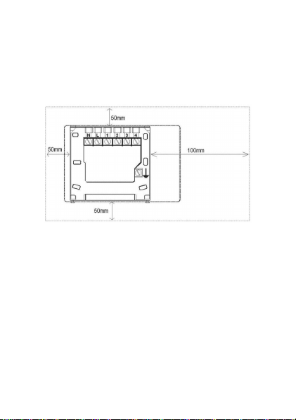
from dust and debris. The backplate should be fitted with the
wiring terminals located at the top and in a position that allows a
total clearance at least 50mm around the unit.
Direct wall mounting
Offer the backplate to the wall in the position where the
timeswitch is to be mounted, remembering that the backplate fits
to the left hand end of the control. Mark the fixing positions
through the slots on the backplate (fixing centres of 60.3mm),
drill and plug the wall, then secure the backplate in position. The
slots in the backplate will compensate for any misalignments of
the fixings.
Wiring box mounting
The backplate may be fitted directly onto a single gang steel
flush wiring box complying with BS4662, using two M3.5 screws.
CentaurPlus controls are suitable for mounting on a flat surface
only; they must not be positioned on a surface mounted wall box
or on unearthed metal surfaces.
2
Page 3
Electrical connections
All necessary electrical connections should now be made. Flush
wiring can enter from the rear through the aperture in the
backplate. Surface wiring can only enter from beneath the
timeswitch and must be securely clamped. The mains supply
terminals are intended to be connected to the supply by means
of fixed wiring. Recommended cable sizes are 1.00 or 1.5mm .
CentaurPlus timeswitches are double insulated and do not
require an earth connection but an earth connection is provided
on the backplate for terminating cable earth connectors. Earth
continuity must be maintained and all bare earth connectors
must be sleeved. Ensure no earth conductors are left protruding
outside the central space enclosed by the backplate.
2
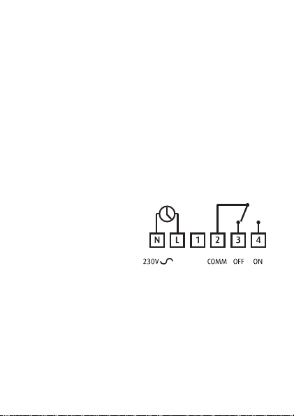
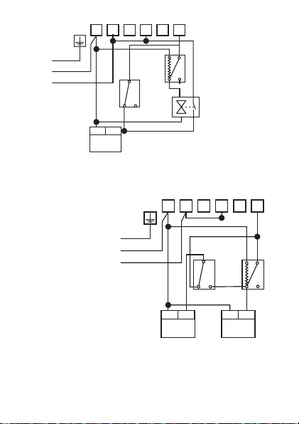
Internal wiring diagram C11 & C17 Series 2
The CentaurPlus has voltage
free contacts.
A link L - 2 is required for
mains voltage applications
50H
Z
New installations
Example circuit diagrams for some typical installations are
shown on the following page. These diagrams are schematic
and should be used as a guide only.
Please ensure that all installations comply with current IET
regulations.
For reasons of space and clarity not every system has been
included and the diagrams have been simplified - for example
some earth connections have been omitted.
3
Page 4
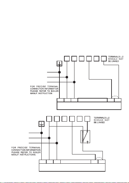
Other control components shown in the diagrams, i.e. Valves,
Room Stats etc are general representations only. However the
wiring detail can be applied to the corresponding models of most
manufacturers, for example Honeywell, Danfoss Randall, ACL
Drayton etc.
Cylinder and Room Thermostat key;
C = Common; CALL = Call for heat or break on rise; SAT =
satisfied on rise; N = neutral.
3
2
BOILER LIVE OUT
REMOVE LINK IF
REQUIRED
4
SWITCHED LIVE
MA I NS
SUPPLY
1. Typical combination
boiler installation
N L 1
E
N
L
NE L
COMBINATION BOILER TERMINALS
RETURN TO BOILER
3
2
N
CALL SAT
BOILER LIVE OUT
4
C
MA I NS
SUPPLY
N L 1
E
N
L
NE L
COMBINATION BOILER TERMINALS
2. Typical combination boiler installation with Room Stat
REMOVE
LINK IF
REQUIRED
4
Page 5
MA I NS
SUPPLY
N L 1
E
N
L
CALL SAT
N L
PUMP &
BOILER
3
4
2
C
N
ROOM
STAT
C
CYL
CALL SAT
STAT
ZONE
VALVE
3. Fully Pumped System with
Room Stat and two port spring
return valve (with auxiliary switch)
on Heating circuit
3
4
2
C
CYL
STAT
N
CALL SAT
C
ROOM
STAT
N L
PUMP
E
MA I NS
N
SUPPLY
L
4. Gravity primary with
pumped Heating via
Room Stat and Cylinder Stat
N L 1
CALL SAT
N L
BOILER
Commissioning the timeswitch
Ensure all dust and debris has been cleared away from the work
area before removing the time switch from its packaging.
5
Page 6
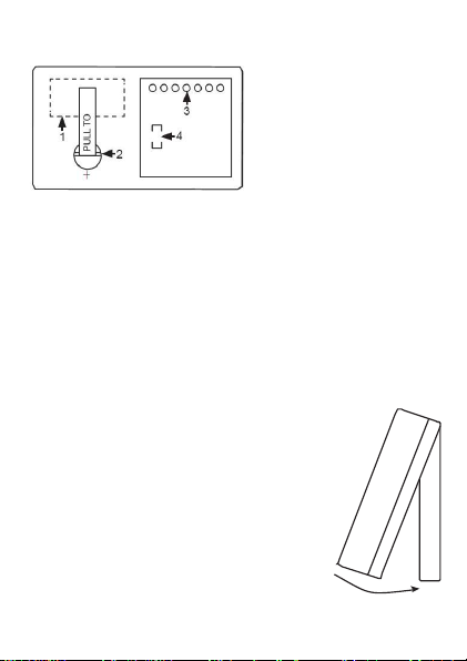
Rear view of CentaurPlus timeswitch
1 - RATINGS LABEL
2 - BATTERY
3 - CONNECTOR PINS
4 - PRODUCTION DATE LABEL
Battery reserve
The battery must be commissioned prior to fitting the control to
the backplate. This is achieved by the means of a
commissioning strip situated in the back of the unit. Pull out the
battery commissioning strip at the back of the timeswitch and reinsert the battery; the reserve is now activated. When the
timeswitch is running the battery reserve clock display will
disappear. This is to prolong the life of the battery.
Fitting the timeswitch
If surface wiring has been used, remove
the knockout/insert from the bottom of the
timeswitch to accommodate it.
Loosen the two 'captive' retaining screws
on the bottom of the backplate. Now fit the
timeswitch to the backplate, ensuring the
lugs on the backplate engage with the
control.
End view of
CentaurPlus timeswitch
6
Page 7
Swing the bottom of the control into position ensuring that the
connection pins on the back of the unit locate into the terminal
slots in the backplate. Tighten the two captive retaining screws
to fix the unit securely. Then switch on the mains supply. On
completion of the installation please reset the timeswitch detailed below.
Resetting the timeswitch
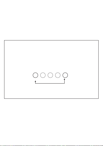
On the CentaurPlus press the SET and SELECT buttons
together. Then release the buttons and the timeswitch will
return to preset factory settings. The preset factory settings
are illustrated on page 6 of the USER GUIDE.
SELECT
SET
The unit can now be programmed to suit the user's
requirements. Please refer to the User Guide provided.
General information
Before handing over the installation to the user, always ensure
that the system responds correctly on all control programmes
and that other electrically operated equipment and controls are
correctly adjusted.
Explain how to operate the controls and hand over the users
operating instructions to the user.
7
Page 8

Specification - CentaurPlus C11 & C17
NP0 08 43 69 00 0
Electrical
Purpose of Control Electronic Central Heating Programmer (1
Channel)
Contact Rating 3(1) Amp 230V AC
Contact Type Micro-disconnection
Supply 230V AC 50Hz only
Protection Class ll
Control Action Type 1B,R
Operating Time Limitation Intermittent
Software Class Class A
Battery Life 10 months continuous operation (minimum)
Mechanical
Dimensions 84mm x 150mm x 29mm
Case Material Thermoplastic, flame retardant
Ball Pressure Test Temperature 75°C
Mounting Industry standard 6 pin wallplate,
independently mounted
Environmental
Impulse Voltage Rating Cat ll 2500V
Enclosure Protection Ip30
Pollution Degree Degree 2
Operating Temperature Range 0°C to +40°C
Compliance
Design Standard EN 60730-2-7, BS EN 60730-1,
BS EN 60720-2-7
Secure Meters (UK) Ltd
Secure House, Lulworth Close,
Chandler's Ford,
Eastleigh, SO53 3TL, UK
t: +44 1962 840048 f: +44 1962 841046
www.securemeters.com
Part Number P84369 Issue 6
 Loading...