

Page 1
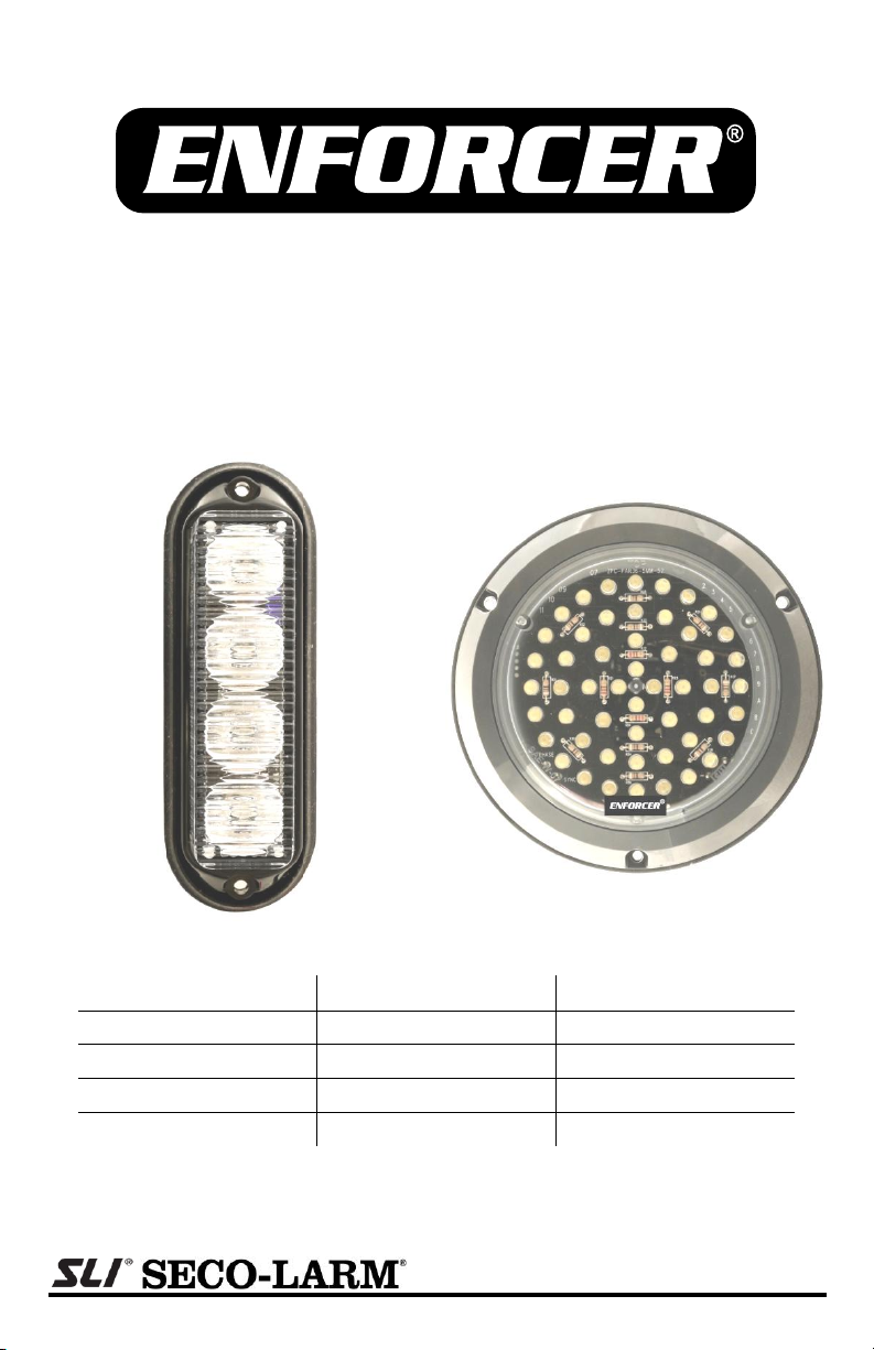
SL-1311-MA
SL-1302-MA
High Intensity 1Wx4 LED Module
52 LED Disk Module
Note: Model numbers that end with “Q” or that have a round green “Q” sticker signify RoHS-compliant products.
Model
Model
LED Color
SL-1311-MA/C
SL-1302-MA/C
Clear
SL-1311-MA/R
SL-1302-MA/R
Red
SL-1311-MA/B
SL-1302-MA/B
Blue
SL-1311-MA/A
SL-1302-MA/A
Amber
Manual
Page 2
ENFORCER
4 High intensity 1W LEDs. (SL-1311-MA)
4 LED colors available.
52 High intensity LEDs. (SL-1302-MA)
Synchronize up to 15 units.
19 Different programmable flash patterns.
Weather (IP 66) and vibration resistant.
Operating life rated 100,000 hours.
Flexible input power (10~30 VDC).
SL-1311-MA
SL-1302-MA
High Intensity 1W LED Module ............... x1
52 LED Disk Module ............................... x1
Mounting screws ..................................... x2
Mounting Screws..................................... x3
Rubber gasket ........................................ x1
Rubber gasket ......................................... x1
Mounting flange ...................................... x1
Mounting flange....................................... x1
Manual .................................................... x1
Manual .................................................... x1
SL-1311-MA
SL-1302-MA
Housing shape
Rectangular
Circular
# of LEDs
4 High intensity 1W LEDs
52 High intensity LEDs
Current draw*
560mA@12VDC
300mA@24VDC
640mA@12VDC
320mA@24VDC
Operating voltage
10~30 VDC
Electrical protection
Reverse polarity protected
Operating life
LEDs rated at 100,000 hours (>11 years)
# of flash patterns
19 (programmable)
Synchronization
Sync or Alternate up to 15 units
IP Rating
IP 66
Operating temperature
-22°~150° F (-30°~65° C)
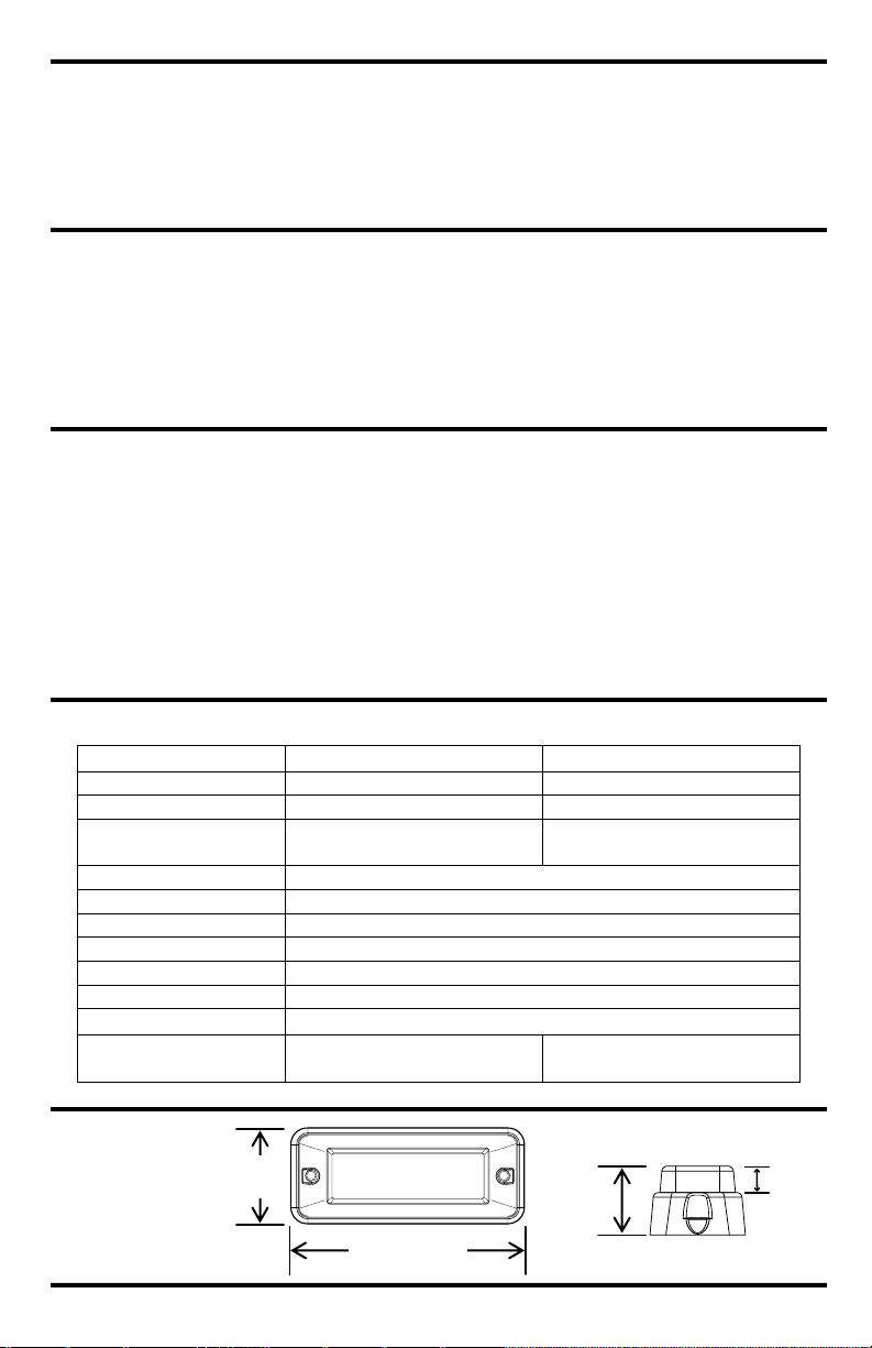
Dimensions
41/2”x11/48”x13/16”
(122x41x30 mm)
41/4”x11/4”
(109x31 mm)
11/4”
(32mm)
41/2” (114mm)
13/16”
(30mm)
9
/16”
(14mm)
®
High Intensity 1Wx4 LED Module and 52 LED Disk Module
Features:
Parts List:
Introduction:
The ENFORCER SL-1311-MA series of High Intensity 1Wx4 LED Module strobe lights features
next generation LED technology with four 1 watt LEDs in a very compact package.
The ENFORCER SL-1302-MA series of 52 LED Disk Module strobe lights features 52 LEDs in a
compact circular housing providing excellent illumination in a low profile package.
These strobe lights all offer 19 selectable flash patterns, potted weather (IP 66) and vibration
resistant circuitry, multi-unit synchronization (sync or alternate) and 10~30 VDC operating
voltage, making them excellent for a wide range of security and informative applications.
Specifications:
*Figures shown are max. Current draw will vary depending on flash pattern.
Dimensions:
SL-1311-MA
2 SECO-LARM® U.S.A., Inc
Page 3

ENFORCER
41/4” (109mm)
11/4”
(31mm)
SL-1302-MA
or
SL-1311-MA
SL-1302-MA
or
SL-1311-MA
Power
Supply
Black wire
Yellow wire
White wire
Red wire
Black wire
Yellow wire
White wire
Red wire
SS-032Q
(Optional SPST
Switch)
White wire
Connect to power
supply to set
alternating flash.
See description
below.
SL-1302-MA
®
High Intensity 1Wx4 LED Module and 52 LED Disk Module
Wiring and Installation:
Wiring the strobe:
1. Black wire: Connect to power supply negative (-) terminal or ground.
2. Red wire: Connect to power supply positive (+) terminal 10~30 VDC.
NOTE: It is recommended to fuse each unit @ 1A.
3. Yellow wire:
Programming Flash Patterns: Connect an optional SPST momentary switch such as
ENFORCER SS-032Q to program the strobe light flash patterns. See connection diagram
above, and the section Flash Patterns on page 4 for more instructions.
Synchronizing Multiple Units: Connect the yellow wires of multiple units to synchronize
their flash patterns.
NOTE: All units must be set to the same flash pattern.
Connect the yellow wires of additional units to synchronize up to 15 strobes.
4. White wire (optionally connect to set alternating flash):
Alternating Flash: Strobes can synchronize in an alternating flash pattern. For example,
when Strobe A flashes ON, Strobe B will flash OFF, etc. Synchronize all strobes. Connect
the white wire to the power supply only for strobes that should alternate with the others.
Mounting the strobe:
1. Choose a mounting surface and drill a hole large enough to allow strobe wires to pass.
2. SL-1311-MA: Feed the wires through the hole in the rubber gasket and the mounting surface.
SL-1302-MA: Feed the wires through the hole and place the rubber gasket around the LED.
3. Place the mounting flange over the LED module. Check it is properly seated on the rubber
gasket and that gasket and mounting surface seal to maximize weather resistance.
4. Align the holes in the gasket and flange and use the self-tapping screws to secure unit in place.
Mounting Accessories: (not included)
SL-1302FM: Rubber flush mount grommet for SL-1302-MA.
SL-1302SM: Replacement plastic mounting flange for SL-1302-MA.
SL-1311SM: Replacement plastic mounting flange for SL-1311-MA.
SECO-LARM® U.S.A., Inc 3
Page 4

ENFORCER
Pattern #
Flash pattern
Pattern #
Flash pattern
1
Randomly cycles all patterns
Alternates between Set 1 LEDs and Set 2 LEDs
2
Single flash each set
6
Rapid flash with fast alternation
3
Double flash each set
7
Ultra rapid flash with slow alternation
4
4x flash each set
8
Pattern 2 / Pattern 4
5
5x flash each set
9
Pattern 2 / Pattern 6
All LEDs light together
10
Single flash
14
Rapid flash
11
Double flash
15
Bursts of ultra rapid flash
12
4x flash
16
Pattern 10 / Pattern 12
13
5x flash
17
Pattern 10 / Pattern 14
Other
18
Set 1 steady ON; Set 2 double flash
19
All LEDs steady ON
MiSL-13xx-MA_1006.docx
PITJW2
®
High Intensity 1Wx4 LED Module and 52 LED Disk Module
Flash Patterns:
1. LEDs are grouped in two sets, Set 1 and Set 2.
SL-1311-MA: Left pair of LEDs are Set 1; right pair of LEDs are Set 2.
SL-1302-MA: Outer two rings of LEDs are Set 1; inner two rings of LEDs are Set 2.
2. To change patterns, momentarily connect the strobe’s yellow wire to +VDC:
a. Once, to move to the next pattern.
b. Three times in rapid succession to reset to Pattern 1.
Hint: Use a programming switch (not included)—see Wiring and Installation on page 3.
5. After changing, the flash pattern will first run one time, pause, then begin repeating.
6. Internal memory will retain last setting when power is disconnected.
WARRANTY: This SECO-LARM product is warranted against defects in material and workmanship while
used in normal service for a period of one (1) year from the date of sale to the original consumer customer.
SECO-LARM’s obligation is limited to the repair or replacement of any defective part if the unit is returned,
transportation prepaid, to SECO-LARM. This warranty is void if damage is caused by or attributed to acts of
God, physical or electrical misuse or abuse, neglect, repair, or alteration, improper or abnormal usage, or
faulty installation, or if for any other reason SECO-LARM determines that such equipment is not operating
properly as a result of causes other than defects in material and workmanship.
The sole obligation of SECO-LARM, and the purchaser’s exclusive remedy, shall be limited to replacement
or repair only, at SECO-LARM’s option. In no event shall SECO-LARM be liable for any special, collateral,
incidental, or consequential personal or property damages of any kind to the purchaser or anyone else.
NOTICE: The information and specifications printed in this manual are current at the time of publication.
However, the SECO-LARM policy is one of continual development and improvement. For this reason,
SECO-LARM reserves the right to change specifications without notice. SECO-LARM is also not
responsible for misprints or typographical errors.
Copyright © 2010 SECO-LARM U.S.A., Inc. All rights reserved. This material may not be reproduced or
copied, in whole or in part, without the written permission of SECO-LARM.
SECO-LARM
®
U.S.A., Inc.
16842 Millikan Avenue, Irvine, CA 92606 Website: www.seco-larm.com
Tel: 800-662-0800 / 949-261-2999 Fax: 949-261-7326 E-mail: sales@seco-larm.com
4 SECO-LARM® U.S.A., Inc
 Loading...