

Seco-Larm SL-1301-BAQ-C, SL-1301-BAQ-G, SL-1301-BAQ-R, SL-1301-BAQ-A, SL-1301-BAQ-B User Manual
Page 1
Manual
LED Strobe Lights
Model #
Color
SL-1301-BAQ/R
Red
SL-1301-BAQ/B
Blue
SL-1301-BAQ/A
Amber
SL-1301-BAQ/C
Clear
Model #
Color
SL-1301-BBQ/R
Red
SL-1301-BBQ/B
Blue
SL-1301-BBQ/A
Amber
SL-1301-BBQ/C
Clear
5 LED Strips
10 LED Strips
(SL-1301-BAQ shown)
Operating life of over 50,000 hours
(over 5.7 years)
6 different flashing options
Adjustable flashing speed
Simple 2-wire installation
4 lens colors available for each model
Same size as the SL-126Q strobe light
Backup battery available for
continuous lighting applications
Visible in all directions
Page 2
LED Strobe Lights
ENFORCER SL-1301-B Series LED Strobe Lights provide all of the functions of a regular strobe light and
much more. Each strobe light has an operating life of 50,000 hours—over 160 times the operating life of a
regular strobe light.
The SL-1301-B series also has 6 selectable flashing options with adjustable flashing speed, making the LED
strobe light suitable for many applications. It has a 9-Volt backup battery option making it ideal for
continuous lighting applications and is engineered so that it is visible from all directions.
SL-1301-B Series LED Strobe Lights come in two models—a 5 LED series or a brighter 10 LED series.
Introduction
SL-1301-BAQ
SL-1301-BBQ
# of LED groups
5
10
Operating voltage
/R models (Red LEDs)
6~15 VDC
/A, /B, /C models (White LEDs)
9~15 VDC
Current drain
Rotate clockwise
60mA
120mA
Strobe
60mA
120mA
Steady ON
200mA
400mA
Flash with progressive ON
200mA
400mA
Rotate back and forth
200mA
400mA
Flash with progressive ON/OFF
200mA
400mA
Adjustable flashing
speed
Maximum setting
260 times/minute
Minimum setting
30 times/minute
Operating life
Over 50,000 hours (over 5.7 years)
Backup battery life
Steady ON
Up to 2 hours*
Strobe/Flashing
Up to 4 hours*
Operating temperature
-4°~158° F (-20°~70° C)
Electrical protection
Reverse polarity protected
IP rating
IP66
Base
High-impact black ABS
Lens
High impact resistant acrylic
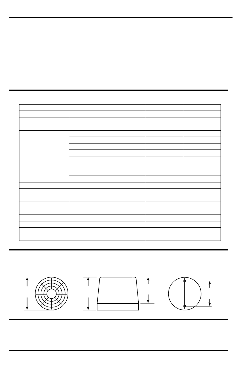
Dimensions
315/16”x229/32” (100x74 mm)
Specifications
Dimensions
Top View
Bottom View
Parts List
1 x LED Strobe Light
1 x Manual
315/16”
(100mm)
23/64”
(52mm)
24/5”
(71mm)
Front View
2 x Mounting Screw
with “O” ring
*Estimated
229/32”
(74mm)
SECO-LARM® U.S.A., Inc.
Page 3

Overview
Installation
5. Connect the wires to their respective locations on an alarm
control panel or other security panel.
6. Remove the lens and mount the LED strobe light to the
surface using the two included mounting screws. If screws
are fastened too tightly, the “O” rings will be damaged.
7. Select the flash pattern using the DIP Switch (see back
page for details) and adjust the speed using the control pot
(clockwise to increase, counterclockwise to decrease).
8. If needed, install backup battery. (See below.)
9. Replace lens. If lens is fastened too tightly, the “O” ring
will be damaged.
WARRANTY: This SECO-LARM product is warranted against defects in material and workmanship while used in normal service for a
period of one (1) year from the date of sale to the original consumer customer. SECO-LARM’s obligation is limited to the repair or
replacement of any defective part if the unit is returned, transportation prepaid, to SECO-LARM. This warranty is void if damage is caused
by or attributed to acts of God, physical or electrical misuse or abuse, neglect, repair, or alteration, improper or abnormal usage, or faulty
installation, or if for any other reason SECO-LARM determines that such equipment is not operating properly as a result of causes other
than defects in material and workmanship.
The sole obligation of SECO-LARM, and the purchaser’s exclusive remedy, shall be limited to replacement or repair only, at SECO-LARM’s
option. In no event shall SECO-LARM be liable for any special, collateral, incidental, or consequential personal or property damages of any
kind to the purchaser or anyone else.
Troubleshooting
The LED strobe light does not turn on.
Check the LED strobe light’s power source.
The LED strobe light does not flash correctly.
Disconnect power, configure correct flash pattern, and
reconnect power.
Backup battery
jumper
1. Before starting, please read this manual carefully and keep
it for future reference.
2. Be sure to use the LED strobe light within the given
electrical limits.
3. Decide where the LED strobe light is to be mounted. Use a
pencil to mark the location of the two mounting screws.
4. Drill a hole through the wall or surface where the LED
strobe light is to be mounted. Run the LED strobe light’s
ground (black) and power (red) wires through the wall.
Note: For surface wiring applications, remove the thinnedout slot with a pair of pliers.
Backup Battery
1. Use a screwdriver to loosen the circuit board screws.
2. Carefully remove and flip the circuit board. The battery
holder is attached at the back side of the circuit board.
3. Connect a 9-Volt battery to the battery connector.
4. Replace circuit board and circuit board screws.
5. Turn the backup battery on or off using the backup
battery jumper.
(Circuit board)
Circuit board
screw
9-Volt Battery
(not included)
DIP switch
Mounting screw with
rubber “O” ring
Control pot
Circuit board
screw
Rubber “O”
ring
LED strips
(5 or 10)
9-Volt battery
holder
(under circuit
board)
Circuit
board
Remove thinned-out
slot for surface wiring
Power
wire
Ground
wire
For continuous lighting applications, the backup battery will
power the LED strobe light in the event of a power loss.
LED STROBE LIGHTS
Page 4

LED Strobe Lights
NOTICE
The information and specifications printed in this manual are current at the time of publication. However, the SECO-LARM policy
is one of continual development and improvement. For this reason, SECO-LARM reserves the right to change specifications
without notice. SECO-LARM is also not responsible for misprints or typographical errors.
Copyright © 2010 SECO-LARM U.S.A., Inc. All rights reserved. This material may not be reproduced or copied, in whole or in
part, without the written permission of SECO-LARM.
U.S.A., Inc.
16842 Millikan Avenue, Irvine, CA 92606 Website: www.seco-larm.com
Tel: 800-662-0800 / 949-261-2999 Fax: 949-261-7326 E-mail: sales@seco-larm.com
PITSW1
Configuring Flash Patterns
DIP Switch
Position
Description of
Flash Pattern
Side View
All LEDs stay on. Ideal for
continuous lighting
applications.
LEDs turn on progressively
clockwise until all LEDs
are lit (sweep), and then
turn off.
LED groups light up one at
a time, rotating clockwise
and counterclockwise.
LEDs turn on progressively
clockwise (sweep), then
turn off progressively
clockwise.
MiSL-1301-B_1001.docx
1 2 3 4 5
6
Steady ON
Flash with
Progressive ON
Rotate Back and Forth
Flash with
Progressive ON/OFF
Top View
IMPORTANT: Before changing flash pattern, disconnect power. Change flash pattern before
reconnecting power. Visit www.seco-larm.com for animated flash pattern samples.
LEDs flash on and off
continuously.
(Default setting)
Strobe
Light rotates clockwise in a
circular fashion
continuously. (Beacon)
Rotate Clockwise
Order Part # 762-509%
SECO-LARM® U.S.A., Inc.
 Loading...