

Page 1

®
Features:
RM-R100-TBQ
Wireless Help Button
Manual
Built-in RF transmitter:
- Powered by 9VDC (battery included)
- Range up to 100ft (30m)*, 433.92MHz
- Over 68 billion (6.8x10
- LED to indicate transmission and low battery
Desktop or wall mounted
*Actual operating range will vary greatly depending on the installation and operating environment.
ABS Plastic single-gang plate with surface
mount back box
Clear 2" square button
10
) possible codes
"Push for Help" message plate included
Requires RM-R100-RB1Q, or SK-910
(433.92MHz) series receiver
Page 2

ENFORCER Wireless Help Button
1x Wireless
Help Button
1x
Back box 2x Wall plate screws
2x Mounting screws
2x
Wall anchors
1x
9V Alkaline battery
4x
Adhesive
rubber
feet 1x Manual
Specifications:
Overview:
Introduction:
The ENFORCER Wireless
Help Button
can be used to wirelessly expand the Room Monitor
Kit
Dimensions:
45/8"x27/8"x2" (117x73x50 mm)
17/16"
(36mm)
Request
45/8"
(117mm)
(RM-R100-KB1Q) with a service/help button. The button is perfect for placing on a desktop, mounting on
walls, or any other location where it is difficult to run wires. The Wireless Help Button combines the very best
of SECO-LARM, flexible wireless solutions and reliable access control.
Parts List:
Operating frequency 433.92MHz
Operating voltage 9VDC
Maximum range 100' (30m)*
Battery life Up to four (4) years (60 uses per day)
Dimensions
Weight 6-oz (178g)
*Actual operating range will vary greatly depending on the installation and operating environment.
Desktop 45/8"x27/8"x17/8" (117x73x48 mm)
Wall mount
9V Alkaline
battery
LED Indicator
Battery clip
Push
for Help
Off: No transmission
Blue: Transmitting
Red: Low battery
button
15
/16"
(24mm)
17/8"
(48mm)
45/8"
(117mm)
Desktop Wall mount
2"
(50mm)
13/4"
(45mm)
Push
for Help
27/8"
(73mm)
2 SECO-LARM U.S.A., Inc.
Page 3
ENFORCER Wireless Help Button
Installation:
RM-R100
-TBQ
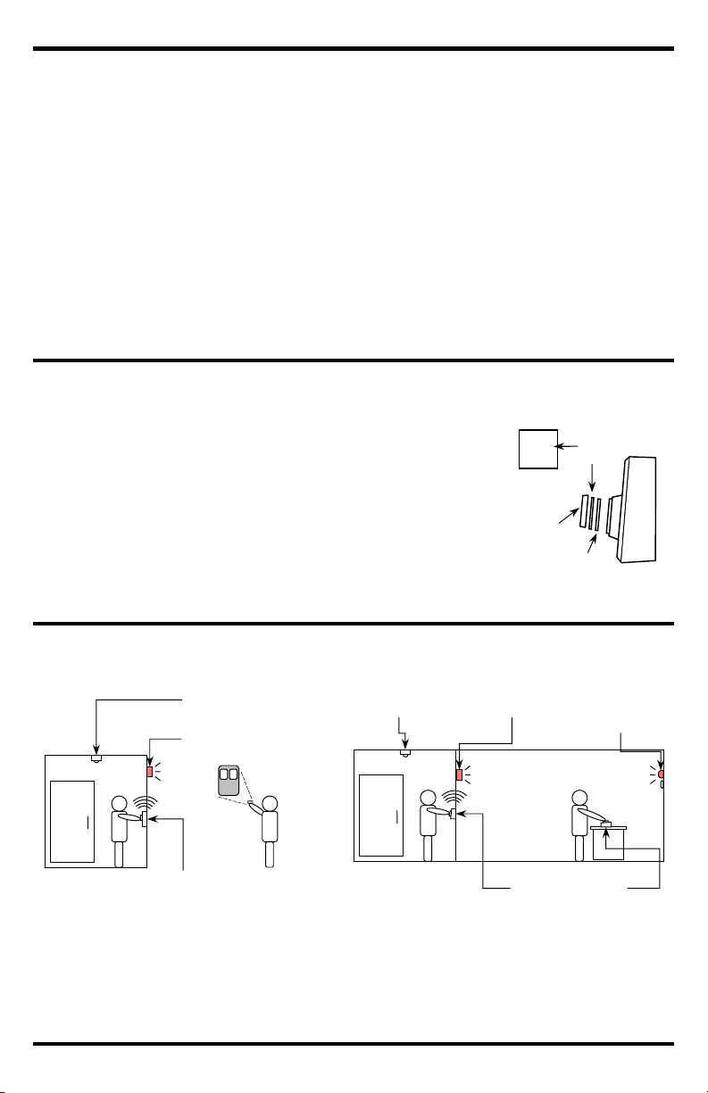
Sample Application
s:
You can easily print your own message plate on very thin card stock, no
Fig. 1
Message
Plate
Transparent
lens
Changing the Message Plate
:
Spacer
Plate
1. Find a suitable location for the Wireless
Help Button
.
Indicator/Receiver
1 2
Wireless
Help Button
Sensor/Transmitter
Room occupied
– i
ndicator/
r
eceiver LED is lit.
*
Light/Buzzer
and
Wireless
Help Button
Sensor/Transmitter
Room occupied
– remote i
ndicator/
r
eceiver LED is
lit.
Indicator/Receiver
*SK-93
9TP2H-NUQ Illustrated
NOTE: Do not house in a metal box as this will greatly reduce the range.
2. The Wireless Help Button can either be wall mounted (taller side of back box on bottom), or placed on a
desktop (taller side of back box on top).
3. Test the operation of the Wireless Help Button in the location where it will be installed before finalizing
the installation.
NOTE: The Wireless Help Button needs to be programmed into the RM-R100-RB1Q or a SK-910
4. Ensure the battery clip is securely connected, mount the Wireless Help Button in the back box according
(433.92MHz) series receiver before testing. See the receiver manual for transmitter learning
procedure.
to the appropriate orientation stated above, and secure it with the two included screws. Apply the
included adhesive rubber feet for desktop applications.
thicker than the included message plate, and trim to 17/8" (37mm) square.
NOTE: Thicker card stock will not allow the transparent lens to fully seat.
1. Use the tip of a very thin screwdriver to pry off the transparent lens
Your
Custom
Message
over the message plate (see Fig. 1).
2. Replace the current plate with the desired message plate, keeping the
spacer plate in place.
3. Check that message plate orientation is correct.
4. Carefully snap the lens assembly back on.
Basic Installation with Room Monitor Kit (RM-R100-KB1Q)
RM-R100-TLQ
RM-R100-TLQ
RM-R100-RB1Q
RM-R100-RB1Q
RF receiver**
(not included)
RM-R100-TBQ
Room occupied
RM-R100-TBQ
Wireless Help Button pressed – indicator/receiver
LED flashes and/or buzzer sounds.
Attendant uses wireless remote* (not included) to
reset the indicator's flashing LED and/or buzzer.
**SK-910 Series receiver (433.92MHz)
Wireless Help Button pressed – light/buzzer connected to a
433.92MHz RF receiver** across the room is triggered and
remote indicator/receiver LED flashes and/or buzzer sounds.
Attendant uses Wireless Help Button (or wireless remote, not
included) to reset the indicator's flashing LED and/or buzzer.
SECO-LARM U.S.A., Inc. 3
Page 4

ENFORCER Wireless Help Button
Changing the Battery:
2-Channel RF Receiver
1-
Button
Handheld
RF
Transmitter
Room Monitor Kit
SK-910RB2
-4Q SK-93
9TP1H
-
BUQ RM-R100-KB1Q
The Wireless
Help Button
has a multi
-
colored LED that illuminates blue when the button is pressed. When the
5. Put the plate back in the back
box and secure it to t
he back
box using the screws on the front.
FCC COMPLIANCE
STATEMENT
FCC ID: K4ER100TB
Q
IS SUBJECT TO THE FOLLOWING TWO
THIS DEVICE MUST ACCEPT
xpressly approved by the party responsible for compliance could void the user’s
IMPORTANT NOTE: To comply with the FCC RF exposure compliance requirements, no change to the antenna or the
to the antenna or the device could result in the device exceeding the RF exposure
NOTICE
:
The SECO
-
LARM policy is one of continual development and improvement. For that reason, SECO
-
LARM
All trademarks
S.A., Inc. All
WARRANTY:
This SECO
-
LARM product is warranted against defects in material and workmanship while
used in normal
LARM’s obligation is limited to the repair or
This Warranty is void if
damage is caused by or attributed to acts of God, physical or electrical misuse or abuse, neglect, repair or alteration,
LARM determines that such equipment
The sole obligation of
’s
LARM be liable for any special, collateral, incidental, or consequential personal or property
Troubleshooting:
16842 Millikan Avenue, Irvine, CA 92606
Website:
www.seco
-
larm.com
Phone: (949) 261
-
2999 | (800) 662
-
0800 Email: sales@seco
-
larm.com
PITSW1
Order Part# 763
-
190%
MI_RM-R100-TBQ_181213.docx
battery begins to run low, the LED will illuminate red. To change the battery:
1. Remove the two screws from the front of the plate and remove the plate from the back box.
2. Remove the battery clip from the 9V battery and remove the battery from the bracket.
3. Place the new battery in the bracket and snap the battery clip to the new battery.
4. Test the unit with the new battery. The LED should illuminate blue.
LED does not light
LED lights blue, but does not
activate lock
Also Available from
THIS DEVICE COMPLIES WITH PART 15 OF THE FCC RULES. OPERATION
CONDITIONS: (1) THIS DEVICE MAY NOT CAUSE HARMFUL INTERFERENCE AND (2)
ANY INTERFERENCE RECEIVED, INCLUDING INTERFERENCE THAT MAY CAUSE UNDESIRED OPERATION.
Notice: The changes or modifications not e
authority to operate the equipment.
device is permitted. Any change
requirements and void user’s authority to operate the device.
service for one (1) year from the date of sale to the original customer. SECOreplacement of any defective part if the unit is returned, transportation prepaid, to SECO-LARM.
Check battery connection
Replace 9V battery
Ensure Wireless Help Button is not housed in a metal box
Test Wireless Help Button closer to the receiver
Clear codes from receiver and re-learn wireless transmitter code
®
:
improper or abnormal usage, or faulty installation, or if for any other reason SECOis not operating properly as a result of causes other than defects in material and workmanship.
SECO-LARM and the purchaser’s exclusive remedy, shall be limited to the replacement or repair only, at SECO-LARM
option. In no event shall SECOdamage of any kind to the purchaser or anyone else.
reserves the right to change specifications without notice. SECO-LARM is also not responsible for misprints.
are the property of SECO-LARM U.S.A., Inc. or their respective owners. Copyright © 2018 SECO-LARM U.
rights reserved.
®
U.S.A., Inc.
4 SECO-LARM U.S.A., Inc.
 Loading...