

Page 1
Manual
16 Outputs
32 Outputs
PH-U1612-PULQ*
PH-U3212-PULQ*
PH-U1612-PTQ
PH-U1612-PTQ
*UL approved models and includes power cable with NEMA 5—15 plug connector.
Rack-Mount DC CCTV
Power Supplies
Note: Model number that end with “Q” or that have a round green “Q” sticker signify RoHS-compliant products.
16 or 32 Outputs
12 Amps at 12VDC
3 Amps per output
12.6~13.5 VDC
field-adjustable output
Compact 1U size
Easy cable management
Bi-color LED status indicator
For rack mounting, wall
mounting, and stacking
PH-U1612-PULQ shown
Page 2

ENFORCER Rack-Mount DC CCTV Power Supplies
Introduction:
ENFORCER Rack-Mount DC CCTV Power Supplies fit into standard 19” IT racks to integrate
smoothly into an existing rack-mount setup. The units provide flexible power, mounting, and
cable-management options to best suit a company’s CCTV power needs in an attractive,
compact package.
Features:
Compact 1U height fits into standard 19” equipment racks
Field-adjustable power output – 12.6~13.5VDC
Dual-color LED status indicator for each output:
Blue
Red
Normal
Fuse tripped
Outputs protected by PTC fuses rated at 3A each
Flexible mounting options:
a. Rack mount: Mount facing forward (easy access to indicator LEDs) or backward (easy
access to connections)
b. Wall mount: Brackets face down for easy attachment on walls, under tables, etc.
c. Desk & Shelf mounting: Units can be stacked together or with other equipment
Flexible cable management options:
a. 2 Cable-management brackets with 3 different mounting points
b. 2 Cable-management hooks with 3 different mounting points
Removable screw terminal blocks for convenient installation and reliable connections
Available with either 16 or 32 outputs
Attractive, high-tech industrial design
Parts List:
Introduction
Features
Parts List
Specifications
Overview
Installation Notes
Table of Contents:
Mounting
Wiring
Replacing the Main Fuse
Cable Management
Camera Control Chart
Troubleshooting and Warranty
2
2
2
3
3
4
4~5
5
6
6
7
8
1x Rack-mount DC CCTV power supply
2x Cable-management brackets
2x Cable-management hooks
4x Rubber feet
1x Power cord
4x M3x6 Cable-bracket screws
2x Mounting brackets for rack, wall, and
surface mounting
1x Spare main fuse (Mounted inside unit,
see page 6)
1x Manual
2 SECO-LARM U.S.A., Inc.
Page 3
Specifications:
PH-U1612-PULQ
PH-U1612-PTQ
PH-U3212-PULQ
PH-U3212-PTQ
Fuse type
PTC*
PTC*
Input voltage
100~240 VAC
Number of outputs
16
32
Total supply current
12A@12VDC max.
Max. current per output
3Amp
Adjustable voltage outupt
12.6~13.5 VDC
Rack-mount height
1U
Dimensions
13/4"x171/2"x1113/32" (45x445x289 mm)
Weight
7-lb 14-oz (3.56kg)
9-lb (4.10kg)
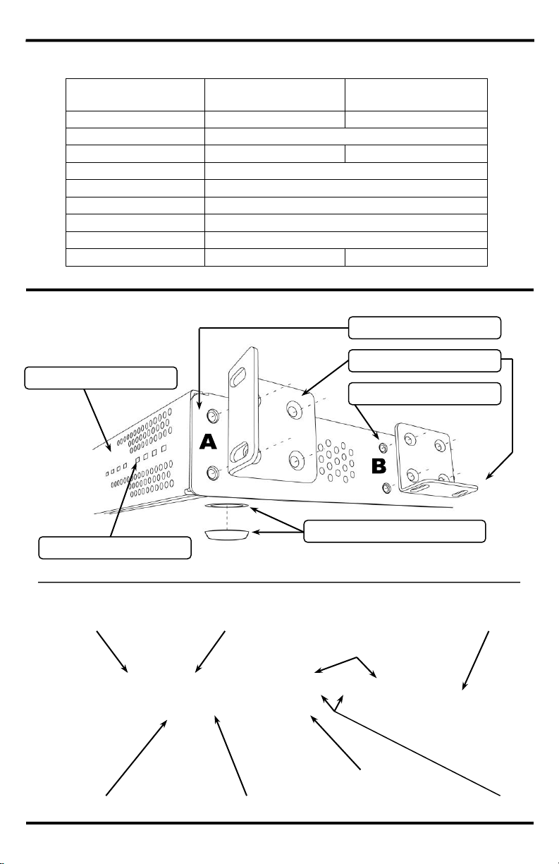
Overview:
Front and Side
Rear
Power supply front panel
A: Front mounting point
B: Center mounting point
Mounting brackets
Rubber foot & mounting point
Output indicator LEDs
Cable management bracket
Power cord socket
Main power switch
Voltage output potentiometers (V
out
)
Power supply rear panel
Main fuse socket
Cable management hook
Terminal blocks
ENFORCER Rack-Mount DC CCTV Power Supplies
SECO-LARM U.S.A., Inc. 3
Page 4

ENFORCER Rack-Mount DC CCTV Power Supplies
1. Remove the mounting screws from the middle mounting points on the left and right sides of the
chassis.
2. Screw the left and right mounting brackets on, facing downward.
3. Make sure no ventilation holes are blocked when the unit is in place.
4. Use screws or bolts (not included) to mount the unit in the desired location.
Note: Make sure that the screws/bolts and mounting surface can support the weight of the unit.
1. Double-check DC output voltage before connecting cameras.
2. FOR INDOOR USE ONLY. Do not install the unit outdoors or expose it to rain or moisture.
3. For professional installation and use only. Installation must conform to all local codes.
4. Avoid installing the unit near heat-generating or heat-sensitive equipment.
5. To prevent shock, do not open the housing. There are no user-serviceable parts inside.
Installation Notes:
Mounting:
1. Decide on a location to install the unit, away from moisture, high humidity, heat sources, etc.
2. Make sure there is enough space around the unit so air can flow in and out for cooling
purposes.
3. Be sure ventilation holes are not blocked by other equipment, rack housing, walls, etc.
4. To avoid undesirable operation in either the product or other equipment place the unit at
least 12” (30cm) from any television monitor or other radiation-producing, radiation-sensitive,
or heat-producing equipment such as heaters, radiators, etc.
1. Units may be stacked one on top of the other, or with other equipment.
2. Make sure the rubber feet are firmly attached to the bottom of the unit and that no ventilation
holes are blocked. (See Overview, pg. 3)
Shelf/table mounting
Wall mounting
Mounting bracket
Middle mounting point
Bracket facing down
4 SECO-LARM U.S.A., Inc.
Page 5

1. Unplug terminal blocks from their sockets for easy installation.
2. Connect equipment power input cables to the screw terminals side by side in N/P pairs.
3. Screw the terminals closed. Once done, reinsert the terminal blocks back into their slots.
4. Adjust channel voltage for each bank of terminal blocks using the voltage output
potentiometers (V
out
) for each bank.
Note: Group cameras with similar power-cable lengths on the same terminal block bank
and adjust the voltage output potentiometers (V
out
) to compensate for voltage drops. Test
voltage after changing settings.
5. Connect the unit’s power cord to a 120V outlet and switch on the unit.
6. Front-panel LEDs should glow blue to show output is on.
7. Test the output at the camera end of each power cable to be sure voltage is correct.
Caution: Always test output voltage before connecting cameras or other equipment.
Rack mounting
1. Forward-facing installation (for easy view of LED indicators):
a. Remove the mounting screws from the mounting points at the front of the unit.
b. Screw the mounting brackets onto the front of the unit.
2. Backward-facing installation (for easy access to terminal blocks and ON/OFF switch):
a. Remove the mounting screws from the mounting points at the back of the unit.
b. Screw the mounting brackets onto the back of the unit.
3. Find an unused 1U space in the equipment rack and screw the unit in place.
4. Leave at least 0.5U above and below the unit for ventilation.
Note: No rear support rails are needed. The unit can be fully supported using the mounting
brackets provided.
Wiring:
Mounting screws (not included)
Power supply mounted facing forward
Mounting brackets mounted front/back
Power supply mounted facing backward
Equipment rack vertical supports
ENFORCER Rack-Mount DC CCTV Power Supplies
SECO-LARM U.S.A., Inc. 5
Page 6

ENFORCER Rack-Mount DC CCTV Power Supplies
1. There are two cable management options included with the product:
a. Cable-management brackets (x2). Screw the brackets onto any of the three mounting points
on the rear of the unit with the included M3x6 screws. Mount the brackets with the open end
at the top.
b. Cable-management hooks (x2). Press the white plastic hooks into any of the three mounting
holes on the rear.
Note: Cable-management hooks, once inserted, cannot be removed.
2. Mount the brackets and route power cables in a way that best suits the installation. Be sure to
leave slack in the cable to ease future maintenance. Use cable ties to reduce cable tension.
Caution: Replace only with same fuse type and rating.
1. Find the main fuse at the back of the unit, between the power cord socket and the
ON/OFF switch.
2. To check or replace the fuse, first power down the unit and disconnect the power cord.
3. Use a flat-head screwdriver to gently lever the fuse holder out at the place indicated in the
diagram below. Be careful not to damage the soft plastic fuse holder with the screwdriver.
Replacing the Main Fuse:
Cable Management:
To cameras
Cable management hook
Cable management bracket
To cameras
Use cable ties to secure
cables to cable
management bracket
Fuse holder
Lever fuse holder here
USE ONLY WITH A 250V FUSE
6 SECO-LARM U.S.A., Inc.
Page 7

Channel
Camera Model and Description
0
SAMPLE – EV-122C-DVB3Q / Gray Vandal Rollerball Camera, 3.6mm, 480TVL
1
2
3 4
5
6 7
8
9
10
11
12
13
14
15
16
17
18 19
20
21 22
23
24 25
26
27 28
29
30 31
32
Camera Control Chart:
Use the chart provided below to keep track of which cameras are connected to which channels.
ENFORCER Rack-Mount DC CCTV Power Supplies
SECO-LARM U.S.A., Inc. 7
Page 8

ENFORCER Rack-Mount DC CCTV Power Supplies
Troubleshooting:
Power does not turn on
Check front panel LEDs and rear main fuse.
Ensure the power cord is firmly in its socket.
Power cycles on and off
The unit may be overheating. Check for heat
sources nearby and ensure ventilation holes are
free from obstruction.
Voltage drop is large
Use 18 gauge or thicker wire.
The camera case is hot
Check that the correct power is being supplied.
Also Available from SECO-LARM:
16-Channel Passive
Video Transceiver
EB-P116-01Q
Cut cost and complexity
by sending CCTV signals
over Cat5e/6 cables up to
1,950ft (600m).
ST-BT03Q
Perform 6 different tests
including voltage drop,
voltage with load,
polarity, and continuity.
EB-P501-02Q
Transmit video, power,
and data signals over a
single Cat5e/6 cable up
to 1,950ft (600m).
PS-U Series
Available with 4, 9, 18,
and 36 fused outputs.
6Amp or 12Amp supply
current. UL Listed.
12V/24DC Tester with
Continuity
Passive Video Balun with
Power or Data Pass-Through
12VDC Switching
CCTV Power Supplies
CAUTION: To reduce the risk of electric shock, do
not open the product case. There are no user
serviceable parts inside. Refer servicing to qualified
service personnel.
WARRANTY: This SECO-LARM product is warranted against defects in material and workmanship while used in normal
service for a period of one (1) year from the date of sale to the original consumer customer. SECO-LARM’s obligation is
limited to the repair or replacement of any defective part if the unit is returned, transportation prepaid, to SECO-LARM.
This Warranty is void if damage is caused by or attributed to acts of God, physical or electrical misuse or abuse, neglect,
repair, or alteration, improper or abnormal usage, or faulty installation, or if for any other reason SECO-LARM determines
that such equipment is not operating properly as a result of causes other than defects in material and workmanship. The
sole obligation of SECO-LARM, and the purchaser’s exclusive remedy, shall be limited to replacement or repair only, at
SECO-LARM’s option. In no event shall SECO-LARM be liable for any special, collateral, incidental, or consequential
personal or property damages of any kind to the purchaser or anyone else.
NOTICE: The information and specifications printed in this manual are current at the time of publication. However, the
SECO-LARM policy is one of continual development and improvement. For this reason, SECO-LARM reserves the right
to change specifications without notice. SECO-LARM is also not responsible for misprints or typographical errors.
Copyright © 2013 SECO-LARM U.S.A., Inc. All rights reserved. This material may not be reproduced or copied, in whole
or in part, without the written permission of SECO-LARM.
U.S.A., Inc.
16842 Millikan Avenue, Irvine, CA 92606
Tel: 800-662-0800 / 949-261-2999 Fax: 949-261-7326
Website: www.seco-larm.com
E-mail: sales@seco-larm.com
MiPH-Uxx12-PULQ_1309.docx
PITSW1
Order Part # 764-508-1%
8 SECO-LARM U.S.A., Inc.
 Loading...