

Page 1
®
PC-U
1820-PULQ shown
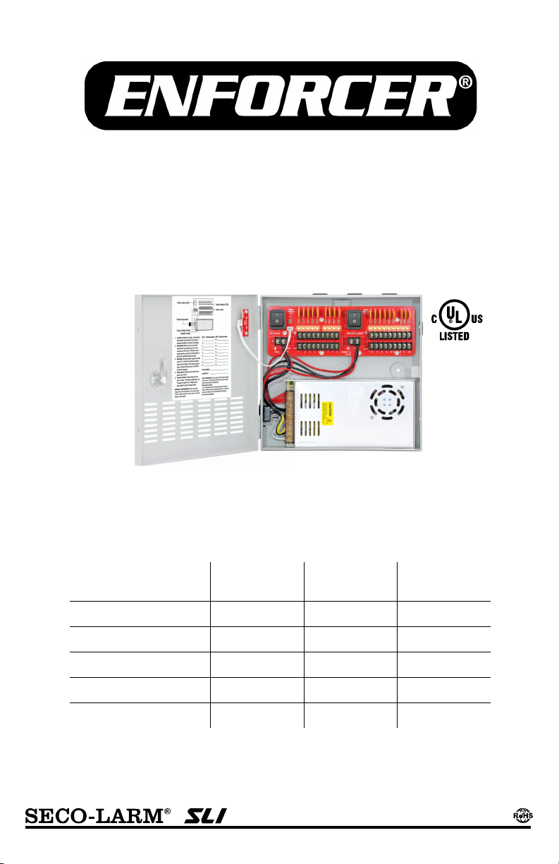
12VDC Switching CCTV Power Supply
Manual
Model
Number
PC-U0405-PULQ 4 5A 1.6A
PC-U0910-PULQ 9 10A 1.6A
PC-U1810-PULQ 18 10A 1.1A
PC-U1820-PULQ 18 20A 1.6A
PC-U1830-PULQ* 18 30A 1.85A
*Special order item. Please contact SECO-LARM for details.
Number of
Outputs
Total Supply
Current
Max. Current
per Output
Page 2
ENFORCER 12VDC Switching CCTV Power Supply
Model
PC-
U0405
-
PULQ PC-U0910
-
PULQ PC-U1810
-
PULQ PC-U1820
-
PULQ PC-U1830
-
PULQ
Outputs
4 9 18 18 18
Total supply
Max.
current per
Output fuse
PTC
Output voltage
11.0~13.8
VDC (adjustable by trimpot
, ±10%
)
Input voltage
* 100~22
0 VAC
±10%
(47~63 Hz)
110/220 VAC (50/60 Hz)
LED
Cover Green: AC Input, Red: DC Output
PDM**
Red
: DC Output
Operating
Operating
Dimensions
97/16"x101/4"x23/8" (240x260x60 mm)
10"x10
/16"x31/8" (254x262x79 mm)
4-lb 3-oz
4-lb 7-oz
5-lb 2-oz
6-lb 1-oz
6-lb 4-oz
Specifications:
Overview:
Features:
Parts List:
1x Power supply
1x
Power cord
2x
Rubber rings
2x Keys 1x Manual
•
•
Output indicator LEDs
Output voltage trimpot
100~220 VAC Input*
• New lightweight, cost-effective design
• Improved efficiency
• Adjustable output to reduce voltage drop
current
output
5A 10A 10A 20A 30A
1.6A 1.1A 1.6A 1.85A
Indicators
humidity
temperature
Outputs protected with PTC fuses
• Individual output status LEDs
• Heavy-duty steel case with cover
• Built-in short circuit and overheat protection
90% (non-condensing)
32°~104° F (0°~40° C)
5
Weight
*UL listed for 90~120 VAC
**Power distribution module
(1.89kg)
(2.01kg)
(2.31kg)
(2.76kg)
(2.84kg)
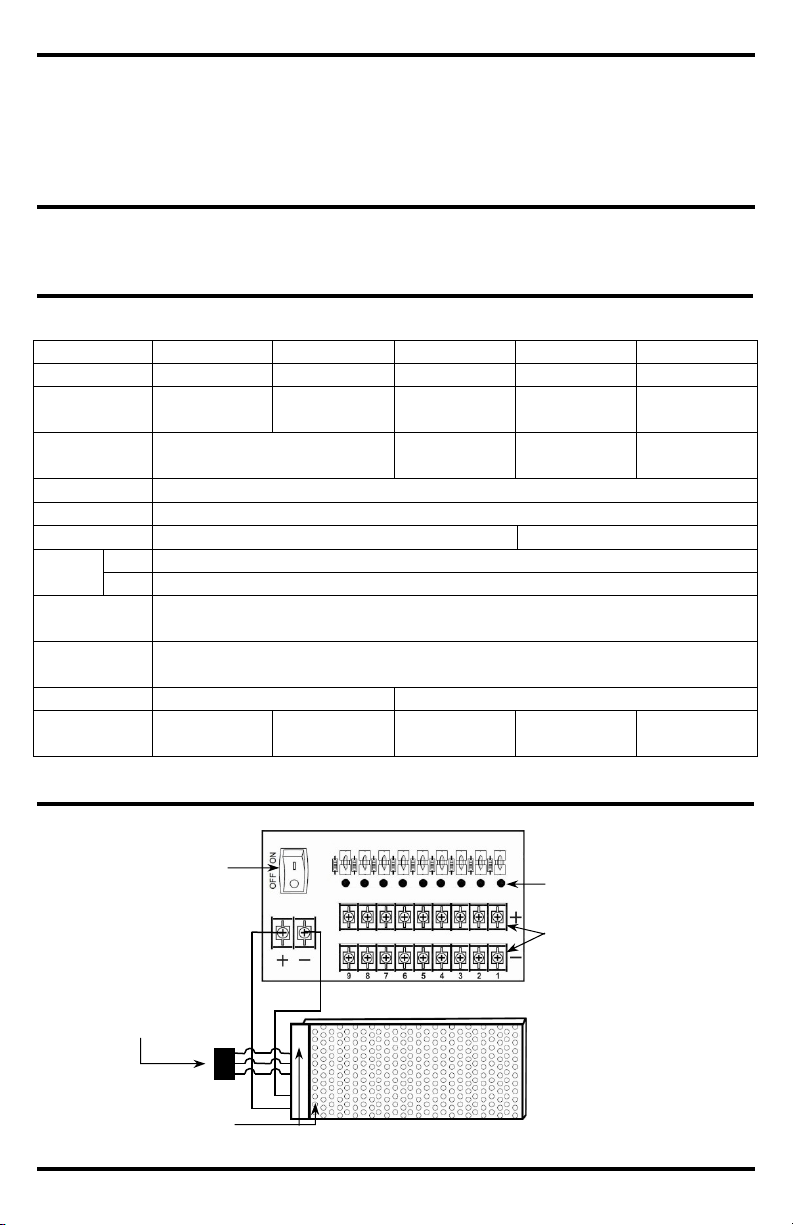
Power output switch
Power output terminals
Power input socket
(location varies)
2 SECO-LARM U.S.A., Inc.
Page 3

ENFORCER 12VDC Switching CCTV Power Supply
Installation:
Power
c
able
k
nock-outs
Fig. 1
- Knock
-Outs
Fig. 3
- Connecting power
Positive (+)
Fig. 4
- Adjusting output
Min.
Max.
LED Indicator Status:
1. Find a suitable location to install the power supply.
The power supply should be installed out of sight,
and in a place protected from weather and high
humidity. The power supply must have adequate
ventilation. Insufficient ventilation may cause
overheating and damage could result.
2. Remove one of more of the cable knock-outs,
depending on how many connections will be made.
Knock-outs are shown in Fig. 1 to the right. If
desired, use an optional bushing, grommet, or other
sleeve to protect wires passing through the hole(s).
3. Screw the power supply to the wall or other mounting
surface using 5/32"x1" (4x26 mm) screws and plastic
anchors (not included). First, screw in the top
screw(s) and hang the power supply. Then, if
applicable, screw in the bottom two screws to fully
secure the unit in place.
4. Plug the power cable into the power input socket
(Fig. 2).
WARNING: Always test output voltage before
connecting devices to the power supply.
5. Connect cameras and other devices to the power
outputs, while observing correct polarity as shown in
Fig. 3. To minimize voltage drop, use 18-guage or
larger wire.
6. If voltage drop is large, adjust the output voltage
trimpot as shown in Fig. 4.
NOTE: The output voltage trimpot changes voltage for
all outputs by ±10%. Test all outputs to ensure
voltage does not exceed device specifications.
Cam lock
Ventilation holes
Fig. 2 - Power Input Socket
outputs
Negative (-)
voltage
Location Color ON OFF
Green
Connected to AC power No AC input
Cover
Red
Power distribution
module
SECO-LARM U.S.A., Inc. 3
Red
DC Output to PDM OK No DC output
Terminal pair of output is
working correctly
Terminal pair of output has no
DC power
Page 4

ENFORCER 12VDC Switching CCTV Power Supply
Installation Notes:
Input Voltage
Note
(for PC
-
U1820
-
PULQ & PC
-
U1830
-
PULQ only)
:
N
OTICE
:
The SECO
-
LARM policy is one of continual development and improvement. For that reason, SECO
-
LARM
rademarks
Inc. All
WARRANTY:
This SECO
-
LARM product is warranted against defects in material and workmanship while
used in normal
LARM’s obligation is limited to the repair or
This Warranty is void if
damage is caused by or attributed to acts of God, physical or electrical misuse or abuse, neglect, repair or alteration,
LARM determines that such equipment
The sole obligation of
’s
LARM be liable for any special, collateral, incidental, or consequential personal or property
IMPORTANT
:
with all national,
will not be held responsible for the use of this product in violation of any
SECO
-
LARM
16842 Millikan Avenue, Irvine, CA 92606
Website:
www.seco
-
larm.com
Phone: (949) 261
-
2999 | (800) 662
-
0800 Email:
sales@seco
-
larm.com
MI_PC-Uxxxx-PULQ_180823.docx
CCTV Power
PA-U0405
-
NULQ
ST-UV12
-
S1.0Q
ST-LA115
-
TPQ
CA-161T / CA
-
151T
•
For 220VAC input voltage,
locate the input voltage switch
110V 220V
ALWAYS TEST OUTPUT VOLTAGE BEFORE CONNECTING DEVICES.
• Indoor use only. Do not mount the unit where it may be exposed to weather or high humidity.
• For professional installation only.
• Installation must conform to all local laws and building codes.
on the bottom of the enclosure. Switch the input voltage
from 110V to 220V as shown in Fig. 5.
Fig. 5 - Input voltage switch
Also Available from
®
:
Supplies
12VDC AC Adapters
Power Converters
shown
shown
shown
state, and local laws and statutes. SECO-LARM
current laws or statutes.
service for two (2) years from the date of sale to the original customer. SECOreplacement of any defective part if the unit is returned, transportation prepaid, to SECO-LARM.
Users and installers of this product are responsible for ensuring this product complies
DC Connectors
shown
improper or abnormal usage, or faulty installation, or if for any other reason SECOis not operating properly as a result of causes other than defects in material and workmanship.
SECO-LARM and the purchaser’s exclusive remedy, shall be limited to the replacement or repair only, at SECO-LARM
option. In no event shall SECOdamage of any kind to the purchaser or anyone else.
reserves the right to change specifications without notice. SECO-LARM is also not responsible for misprints. All t
are the property of SECO-LARM U.S.A., Inc. or their respective owners. Copyright © 2018 SECO-LARM U.S.A.,
rights reserved.
SECO-LARM
®
U.S.A., Inc.
®
4 SECO-LARM U.S.A., Inc.
PICSN7
 Loading...