

Page 1
E-936-S45RRGQ
Caution:
Features:
Typical Applications:
monitoring.
Retro-Reflective Photoelectric Beam Sensor
Manual
• Range 45 ft (14m)
• Weatherproof (IP66) construction for
indoor/outdoor usage
• Pre-wired 6-foot cord
• Bracket and mounting hardware included
for both sensor and reflector
• Adjustable sensing range
• Compact size
• This sensor was not designed to prevent bodily injury or loss of life.
• This sensor was not designed for use in environments where explosive gasses may be present.
• Use of this sensor in certain security applications may be regulated by local laws or codes. SECO-LARM
is not responsible for compliance with such laws or codes.
• Sensor for garage doors or outdoor gates
• Entry detection for store fronts
• Assist in measuring parking distance
• Light on type
IMPORTANT: The E-936-S45RRGQ
conforms to UL325-2016 for gate operators
that use the N.C. or 10kΩ resistor for
Page 2
ENFORCER Retro-Reflective Photoelectric Beam Sensor
Type
Retro-reflective
Sensing range
0.5~45 ft (0.2~14 m)
Operating voltage
12-30V DC/AC 60Hz, 100mA
Standby
70mA@12VDC
Active
55mA@12VDC
Response time
10ms
Light source
IR LED
LED indicators
Yellow LED (Alignment), Red LED (Power on)
SPDT Relay output
(NO/NC/COM, with built-in 10KΩ resistor on N.O. output)
Switching capacity
2A@30VAC/VDC
Enclosure
IP 66 Weatherproof
Operating temperature
-4~131°F (-20~55°C)
Mounting brackets for sensor and reflector
Included
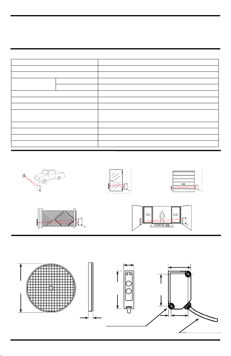
Specifications:
Dimensions:
Reflector
Transmitter/Receiver
3
/8″ (9mm)
31/4″
(82mm)
ENFORCER ®
/16″
(20.5mm)
211/16″
(63mm)
3
/16″
(5mm)
19/16″
(39mm)
2″
(51mm)
11/8″
(29mm)
Parts List:
1x
Transmitter/Receiver
1x
Round Reflector
1x
Reflector Hood for Round/Square Reflector
1x
Sensor Mounting Bracket
1x
Sensor Mounting Bracket
Sample Installations:
Garage Door
Main Entrance Door
Store Entrance
Parking Distance Monitor
Entry Gate
E-931ACC-BLS5Q
Current draw
Trigger output
E-931ACC-BLS1Q
13
3
/16″ (4.5mm) thru holes
2 SECO-LARM U.S.A., Inc.
1
/4″ (6mm) diameter
61/2′ (2m) cable
Page 3

ENFORCER Retro-Reflective Photoelectric Beam Sensor
Fig. 1
Red LED
Yellow LED
Installation and Adjustment:
Sensing Range Adjustment Functions:
The Sensing Range adjustment knob sets how powerful the
infrared signal emitted by the sensor is.
•
•
The objective of this function is to set the appropriate power
of the infrared signal corresponding to the distance between
the
factory default setting is set at “Max.”
Note: If the infrared signal is too strong, the sensor may not
Installation:
1.
2.
3.
4.
Note:
Note:
adjusting the sensor will not turn the yellow LED on,
Adjusting the Sensing Range
After the sensor and the reflector have been properly
inst
for the sensing range. Open the top cover of the sensor as
shown in Fig. 2.
Fig. 2
Min
Starting from the Max. position, slowly turn the knob
may not be able to detect the passing object. In this
clockwise until the desired sensitivity
LED Functions:
Note: Depending on the monitoring system used by the
• Red LED – When ON, it indicates the sensor is powered.
• Yellow LED – When ON, it indicates that the sensor is
properly aligned with the reflector, and the sensor is not
triggered.
Min. Setting – The infrared power signal emitted by the
sensor is at its minimum or weakest.
Max. Setting – The infrared power signal emitted by the
sensor is at its maximum or strongest.
sensor and the reflector of a particular application. The
trigger. If the infrared signal is too weak, the sensor
may be susceptible to false alarms.
counter-clockwise until the yellow LED turns OFF. This
position represents the weakest point of the infrared
signal for this particular application. The setting of the
sensing range must be a little higher than this point, so
turn the knob clockwise to have a little distance from the
weakest point. The ideal setting is midpoint between the
weakest point and Max. Close the top cover securely to
prevent water from entering the sensor.
Note: When turning the knob counter-clockwise from the
Max. position, if the weak point is near the Max.
position then the knob should be set at the Max.
position.
Testing:
1. Power up the sensor. Both LEDs should be ON.
2. Pass the object to be detected between the sensor
and reflector. The yellow LED should turn OFF. This
indicates that the object has been detected.
Note: If a shiny object, such as a chrome-plated item or
something with reflective tape, is within close
proximity of the path of the IR beam the sensor
case it may be necessary to turn the sensitivity
knob countersetting is obtained.
Mount the reflector and the sensor so they face each
other (see pg. 4, "Mounting the Sensor").
Connect power to the sensor (see pg. 4, "Wiring"). The
red LED will turn ON indicating that the sensor is
powered on. If the yellow LED is ON, it indicates that
the sensor and reflector are aligned (although it still
may be necessary to slightly adjust the alignment).
Turn the sensing range knob to Max.
To find the correct alignment, slowly adjust the angles
of the sensor (and/or reflector) up, down, left or right.
Correct alignment is reached when the yellow LED
turns ON.
If
the sensor is at the edge of sensing the signal, and
may not work properly.
:
alled, the next step is to adjust the appropriate setting
SECO-LARM U.S.A., Inc. 3
The E-936-S45RRGQ will not work with gate
Sensing Range
Max
gate motor, it may be necessary to use either the
N.C. output or the built-in 10kΩ resistor on the N.O.
output. Please refer to the gate operator manual
or the gate operator manufacturer for the preferred
monitoring method.
operators that monitor using the “heartbeat”
method.
Page 4

ENFORCER Retro-Reflective Photoelectric Beam Sensor
WARRANTY: This SECO-LARM product is warranted against defects in material and workmanship while used in normal
LARM’s obligation is limited to the repair or
This Warranty is void if
ts of God, physical or electrical misuse or abuse, neglect, repair or alteration,
LARM determines that such equipment
The sole obligation of
ncidental, or consequential personal or property
SECO-LARM
®
U.S.A., Inc.
16842 Millikan Avenue, Irvine, CA 92606
Website: www.seco-larm.com
Phone: (949) 261-2999 | (800) 662-0800
Email: sales@seco-larm.com
NOTICE: The SECO-LARM policy is one of continual development and improvement. For that reason, SECO-LARM
This material may not be reproduced or copied, in whole or
in part, without the written permission of SECO-LARM.
®
PITSW3
MI_E-936-S45RRGQ_160919.docx
Troubleshooting:
Mounting the Sensor:
Wiring:
Note:
1.
2.
For E-931ACC-BLS5Q Bracket
For E-931ACC-BLS1Q Bracket
Connection (5 wires)
Brown
12-30V DC/AC (60Hz), 100mA
(Non polarized)
Blue
Gray (N.O.)
White (COM)
Black (N.C.)
Multi-voltage
Relay Output
10kΩ
Optional Accessories Available from SECO-LARM®:
E-931ACC-HR1Q
E-931ACC-BLS1Q
E-931ACC-BLS5Q
E-931ACC-BLS7Q
E-931ACC-BLS8Q
E-931ACC-BLS6Q
circuit
Can be connected to AC or DC voltage
Maximum cable extension length is
325 ft (100 m)
Sensor does not detect the object.
Yellow LED does not turn on
E-931ACC-R2Q
Square Reflector
E-931ACC-RC1Q
Round Reflector
• Change the angle of the sensor or readjust the sensitivity setting
• Clean the sensor and reflector with a damp (not wet) cloth
• Adjust the reflector and/or sensor for proper alignment
Reflector Hood for
Round/Square Reflector
E-931ACC-BLR2Q
Reflector Bracket
Sensor Bracket
service for 1 (one) year from the date of sale to the original customer. SECOreplacement of any defective part if the unit is returned, transportation prepaid, to SECO-LARM.
damage is caused by or attributed to ac
improper or abnormal usage, or faulty installation, or if for any other reason SECOis not operating properly as a result of causes other than defects in material and workmanship.
SECO-LARM and the purchaser’s exclusive remedy, shall be limited to the replacement or repair only, at SECO-LARM’s
option. In no event shall SECO-LARM be liable for any special, collateral, i
damage of any kind to the purchaser or anyone else.
reserves the right to change specifications without notice. SECO-LARM is also not responsible for misprints.
Copyright © 2016 SECO-LARM U.S.A., Inc. All rights reserved.
4 SECO-LARM U.S.A., Inc.
Sensor Bracket
Wall Bracket
Door Frame Bracket
Single-gang Bracket
 Loading...