

Page 1
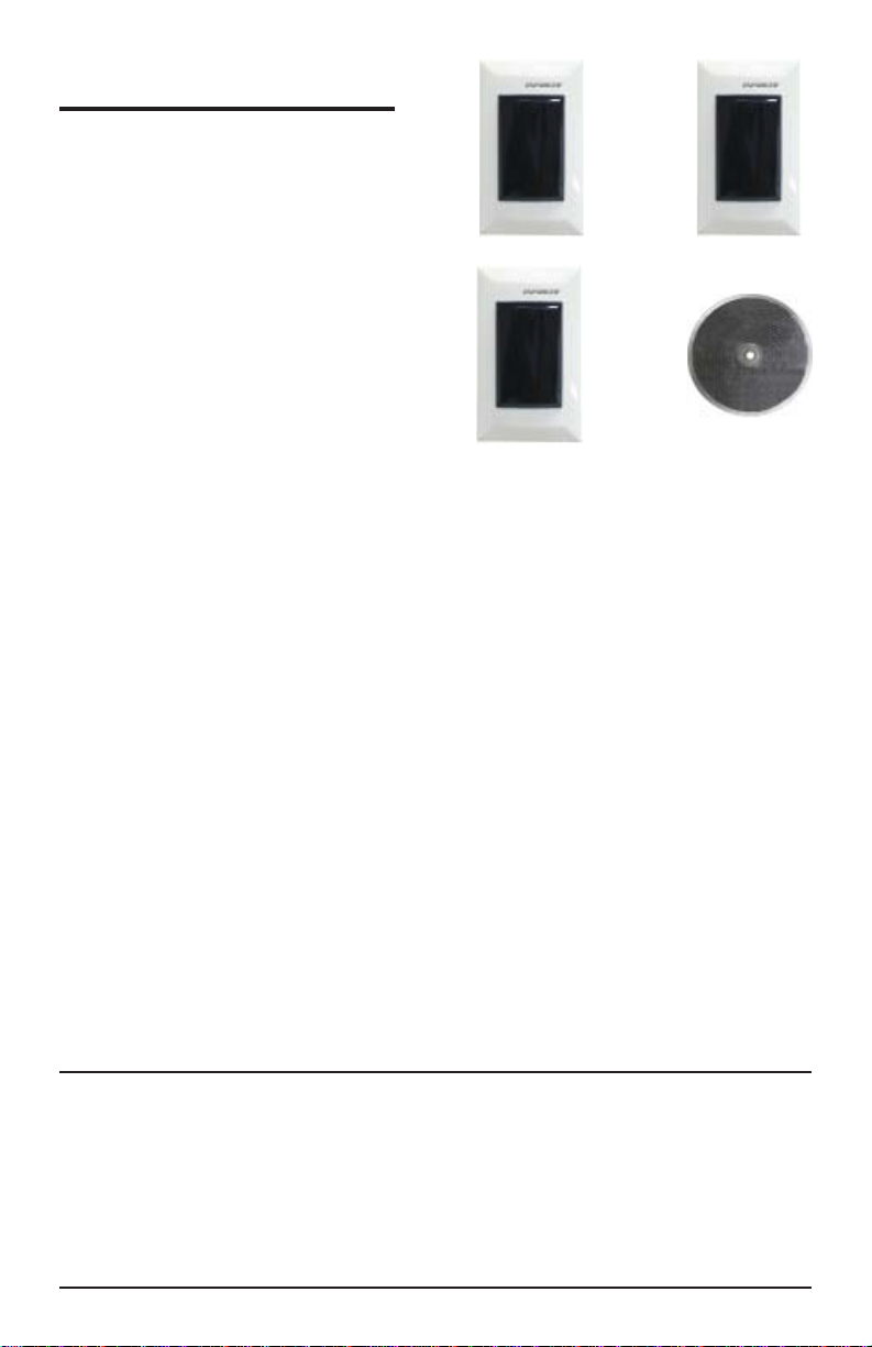
ENFORCER
Sensor
Flush-Mount
Photobeam
E-932-S33TBQ
Sensors
E-932-D33TBQ
Dual Beam
Range: 33ft. (10m)
E-932-S16RRQ
Retro-Reflective
Range: 16ft. (5m)
E-932-S16RRQ
INSTALLATION MANUAL
Features: Typical Applications:
••
•
Range: Up to 33 feet (10m) E-932-D33TBQ
••
Up to 16 feet (5m) E-932-S16RRQ
••
•
For indoor use.
••
••
•
12~18V AC/DC input voltage.
••
••
•
Horizontal and vertical adjustment for easy
••
alignment.
••
•
N.C./N.O./COM relay outputs.
••
•
Entry detection for store fronts.
•
Alarm sensor.
Caution:
•
This sensor was not designed to prevent
bodily injury or loss of life.
•
This sensor was not designed for use in
environments where there is the possibility of
explosive gasses present.
•
Use of this sensor in certain security
applications may be regulated by local laws
or codes. SECO-LARM is not responsible
for compliance with such laws or codes.
Page 2
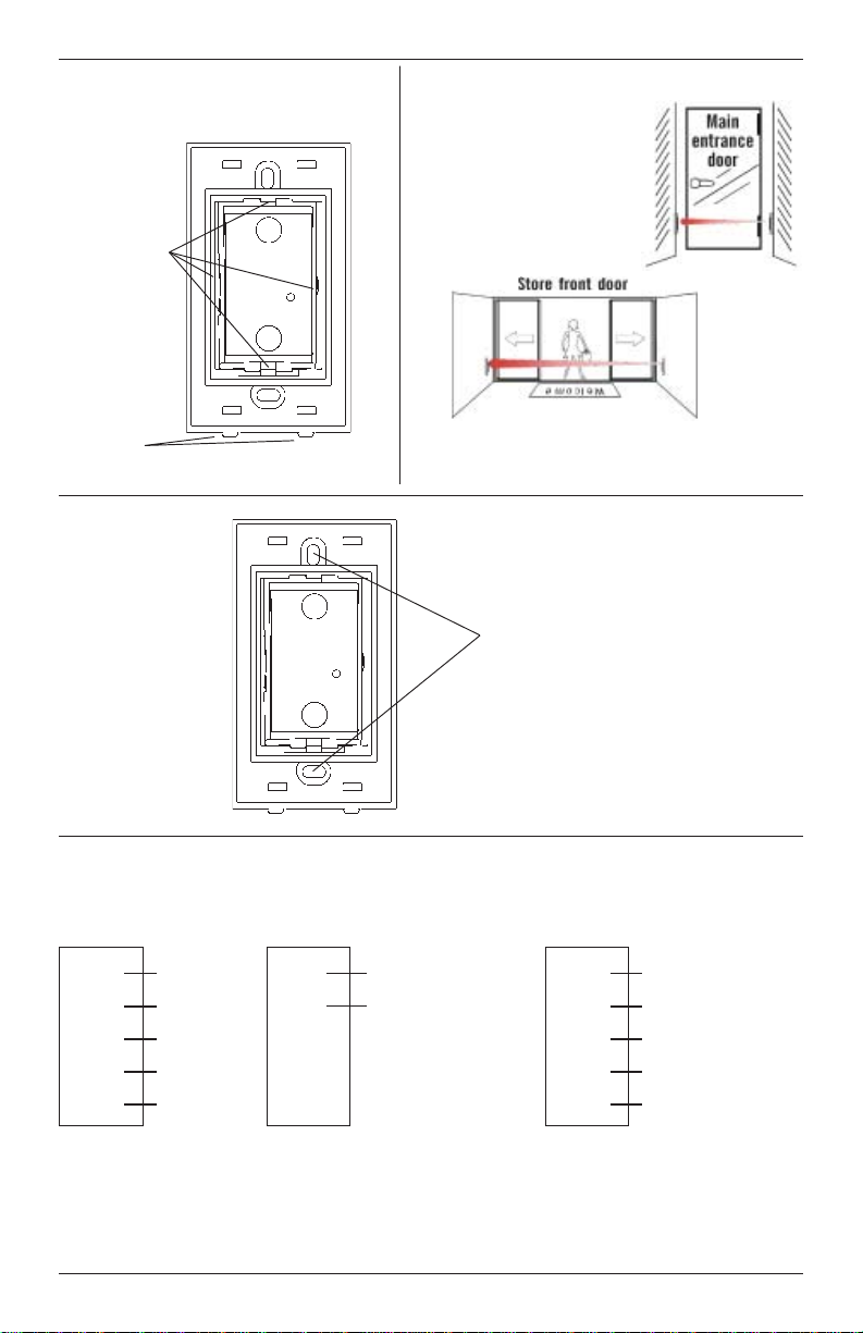
Fig. 1 - Horizontal &
Vertical alignent)
Pivot Points
Tabs Down
Fig. 3 Mounting
Fig. 2 - Sample
Installations
Mounting
Screws. Be
sure to use flat-
head, flush
mounting
screws.
Fig. 4 - Wiring
Red (DC+)
Black (DC-)
RX
Blue (N.C.)
White (COM)
Green (N.O.)
(E-932-D33TBQ) (E-932-S16RRQ)
TX
Red (DC+)
Black (DC-)
2
TX
RX
Red (DC+)
Black (DC-)
Blue (N.C.)
White (COM)
Green (N.O.)
Page 3

Installation and Alignment:
Installation and Alignment:
E-932-S16RRQ
LED functions:
Red (on): Power
Yellow (off): Aligned
Yellow (on): Out of Alignment
Yellow (on) after being aligned: Unit Triggered
Installation:
1. Decide where to mount:
a. The reflector should be directly across from
the transmitter/receiver.
b. The unit should not interfere with normal
movement around the protected area.
2. Wire the unit - Run the wires to the back box
where the sensor is to be mounted. Keep
wires hidden where possible, and expose them
only at the very end where needed to connect
to the transmitter/receiver. (see fig.4)
3. Mount the transmitter/receiver (flush mount)
(fig. 3) - Mount flush to the wall with two
mounting screws.
4. Initial test - Temporarily hold the reflector to the
wall and power up the unit to test alignment
before permanent mounting. (See Power and
Alignment below.)
Power and Alignment
1. Power up the transmitter/receiver. The red LED
will turn ON to indicate power is present. The
yellow LED on the unit will turn OFF to indicate
they are aligned properly.
2. Alignment - If the unit is connected to power,
and the yellow LED does not turn off while the
red LED is on, the unit and reflector are not
aligned. Adjust the unit on its pivot points until
the yellow LED turns off, indicating alignment.
(Fig. 1.)
Testing:
1. Do a walk-through test. Walk between the
transmitter and receiver. This should break the
beam, turn the yellow LED on, and trigger the
alarm panel or warning device.
2. Replace the lens covers on the transmitter/
receiver. Test again one last time.
E-932-D33TBQ
LED functions:
TX RED (on): Power
RX RED (off): Aligned
RX RED (on): Out of Alignment
RX RED (on) after being aligned: Unit Triggered
Installation:
1. Decide where to mount:
a. The transmitter and receiver should be
facing each other.
b. The units should not interfere with normal
movement around the protected area.
2. Wire the unit - Run the wires to the back box
where the sensor is to be mounted. Keep wires
hidden where possible, and expose them only
at the very end where needed to connect to the
transmitter and receiver. (see fig.4)
3. Mount the transmitter/receiver (flush mount)
(fig. 3) - Mount flush to the wall with two
mounting screws.
4. Initial test - Power up the units to test alignment
before permanent mounting. (See Power and
Alignment below.)
Power and Alignment
1. Power up the transmitter and receiver. The red
LED on the transmitter should turn ON to
indicate power is present. The red LED on the
receiver should turn OFF to indicate the two
are aligned properly.
2. Alignment - If the receiver is connected to
power, and if the red LED does not turn off
while the receiver is on, the transmitter and
receiver are not aligned. Adjust the units on
their pivot points until the red LED on the
receiver turns off, indicating alignment. (Fig. 1.)
Testing:
1. Do a walk-through test. Walk between the
transmitter and receiver. This should break the
beam, turn the red LED on, and trigger the
alarm panel or warning device.
2. Replace the lens covers on the transmitter and
receiver. Test again one last time.
3
Page 4

Specifications:
E-932-S16RRQ
Type Reflective beam Dual through beam
Sensing Range 16 ft (5m) 33 ft (10m)
Supply Voltage 12~18VDC 12~18VDC
Current Drain 50mA max. 50mA max.
Response Time 10msec. 10msec.
Light Source IR LED IR LED
LEDs Red (on): Power TX Red (on): Power
Output N.C., N.O., Common N.C., N.O., Common
Switching Capacity 1A@120V (AC/DC) 1A@120V (AC/DC)
Ambient Temp 14°~122°F (-10°~50°C) 14°~122°F (-10°~50°C)
Alignment Angle Vert. ±15°, Horiz. ±15
Yellow (off): Aligned RX Red (off): Aligned
Yellow (on): Out of alignment RX Red (on): Out of alignment
°
E-932-D33TBQ
Vert. ±15°, Horiz. ±15
Troubleshooting:
Trouble Remedy(s)Possible Origin(s)
Sensor does not detect the object.
Red LED does not turn on. No power. Check power.
Yellow LED or RX Red LED
does not turn off.
Red LED lights when object is
detected, but no output.
Object may have a reflective surface
which confuses sensor.
1) Dirty sensor and/or reflector.
2) Reflector and/or sensor is misaligned.
No continuity between sensor and alarm
device.
Change the angle of the sensor
or readjust the sensitivity setting.
1) Clean the sensor and reflector with a
damp (not wet) cloth.
2) Adjust the reflector and/or sensor for
proper alignment.
Check cable from sensor to alarm device.
Test sensor.
°
Warranty:
used in normal service for a period of one (1) year from the date of sale to the original consumer customer.
SECO-LARM’s obligation is limited to the repair or replacement of any defective part if the unit is returned,
transportation prepaid, to SECO-LARM.
This Warranty is void if damage is caused by or attributed to acts of God, physical or electrical misuse or abuse, neglect, repair, or
alteration, improper or abnormal usage, or faulty installation, or if for any other reason SECO-LARM determines that such equipment
is not operating properly as a result of causes other than defects in material and workmanship.
The sole obligation of SECO-LARM, and the purchaser’s exclusive remedy, shall be limited to replacement or repair
only, at SECO-LARM’s option. In no event shall SECO-LARM be liable for any special, collateral, incidental, or
consequential personal or property damages of any kind to the purchaser or anyone else.
Notice:
SECO-LARM policy is one of continual development and improvement. For this reason, SECO-LARM reserves the right to change
specifications without notice. SECO-LARM is also not responsible for misprints or typographical errors.
Copyright © 2007 SECO-LARM U.S.A., Inc. All rights reserved. This material may not be reproduced or copied, in whole or in part,
without the written permission of SECO-LARM.
This SECO-LARM product is warranted against defects in material and workmanship while
The information and specifications printed in this manual are current at the time of publication. However, the
SECO-LARM® U.S.A., Inc.
16842 Millikan Avenue, Irvine, CA 92606
Tel: 800-662-0800 / 949-261-2999 Fax: 949-261-7326
Website: www.seco-larm.com
@
E-mail: sales
seco-larm.com
®
PITSW3
MiE932-D33TBQc.PMD
 Loading...