

Page 1
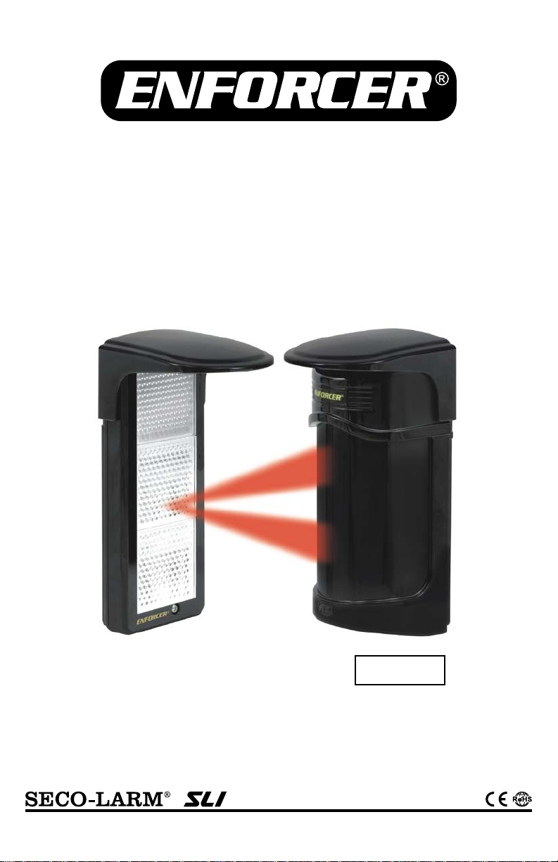
E-931-S50RRLQ
• Up to 50ft (15m) sensing range
• 12~250 VAC/VDC Operation
Patented
50ft Large Reflective Beam Sensor
Manual
• Weatherproof (IP55)
• Beam status LED
Note: Model n umbers that end with “Q” or that have a round green “Q” sticker signify RoHS-compliant products.
• Form C relay rated 0.5A@120VAC
• N.C. Tamper switch rated 0.5A@30VDC
Page 2

ENFORCER 50ft Large Reflective Beam Sensor
Table of Contents:
Features ......................................................... 2
Specifications
Parts List
Dimensions
Overview
Choosing a Location
Wiring Diagram ............................................... 4
Installation ................................................... 5-6
Sample Installations
Adjusting the Response Time
Adjusting the Alignment
Fine
Troubleshooting
Warranty ..........................................................8
Features:
• Reflective beam provides reliable perimeter security, minimizing false alarms from falling
•
reinforces beam strength and provides excellent immunity to false alarms due to
•
•
•
•
•
•
•
Specifications:
Model
E-931-S50RRLQ
Type
50’ Large Reflective Beam Sensor
Sensing range
50’ (15m)
Response time
50~700 ms (Programmable)
Current draw
100mA
Red
No beam signal, triggered
Yellow
Poor beam signal
Green
Connected to power
Operating voltage
12~250 VAC/VDC
Alarm output
NO/NC Relay, 0.5A@120VAC, min. 1s
Tamper output
N.C. Switch, 0.5A@30VDC
IP Rating
IP55
Alignment angle
Horizontal: ±90°, Vertical: ± 5°
Operating temperature
-13°~131° F (-25°~55° C)
Sensor
14.5-oz (410g) (with hood)
Reflector
8.8-oz (250g) (with hood)
Material
PC Resin
................................................. 2
......................................................... 3
..................................................... 3
......................................................... 3
....................................... 4
-Tuning the Sensor ...................................7
leaves, birds, etc.
Lensed optics
rain, snow, mist, etc.
Weatherproof, sunlight-filtering case for indoor and outdoor use
Large reflective beam sensor
Long-range sensing: Up to 50ft (15m)
NO/NC Alarm output
Non-polarized power inputs, 12~250 VAC/VDC
Response time adjustable for nearly all situations
Includes hoods for sensor and reflector
........................................6
..........................7
...................................7
...............................................8
LEDs
Weight
2 SECO-LARM U.S.A., Inc.
Page 3
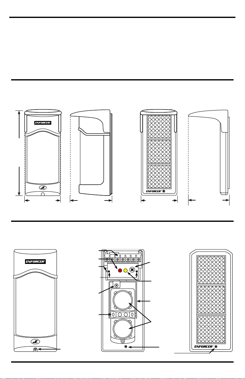
Overview:
Sensor
Reflector
Cover
Signal LED
Response tim e
adjustment
knob
Horizontal
adjustment
bracket
Lens
Terminals
Alarm LED
Voltage output
probes
Vertical
adjustment
Alignment
viewfinder
Captive
Cover screw
Power LED
Parts List:
1x Sensor
1x Reflector
2x Hoods
2x Mounting plates
2x Mounting brackets
2x Pole mounting brackets
1x L
4x Mounting screws
4x Long screws
6x Short screws
1x Rubber gasket
Dimensions:
Sensor with hood
Reflector with hoo d
33/16” (81mm)
39/16” (91mm)
7
3
/
”(182mm)
33/16” (81mm)
39/16” (91mm)
16
-Shaped mounting bracket
ENFORCER 50ft Large Reflective Beam Sensor
screw
SECO-LARM U.S.A., Inc. 3
screw
Page 4

ENFORCER 50ft Large Reflective Beam Sensor
Choosing a Location:
To prevent erratic operation and/or false alarms:
•
•
•
•
•
Do not install the sensor in areas where it may b e
splashed by w ater or direct sea spray.
Do not mount t he sensor near trees, bushes or
Wiring Diagram:
• Polarity does not matter for the power input
•
1 2 3 4 5 6 7
(+)
(–)
COM
N.C.
N.O.
N.C.
N.C.
12~250 VAC/ V DC
Alarm Output
Tamper Output
Avoid strong lights such as the sun or automobile
Wind will not directly cause false alarms, but
could cause leaves or similar objects to fly or
wave into the beams. Therefore, do not mount
near trees, bushes or other leafy vegetation.
Do not mount where the sensor could be
suddenly exposed to a bright light, such as a
floodlight or a passing automobile’s headlights.
Over time, a strong light can affect the life of the
sensor.
Do not let sunlight or any direct beam of light
enter the sensor. If needed, mount so the
reflector, not the sensor, faces the sun.
Do not mount where animals could break the
beams.
Do not mount where the sensor could be
splashed by water or mud.
other leafy v egetation.
headlights shining directly on the sens or.
Connect the N.C. tamper terminal to the tamper circuit of an alarm control panel
4 SECO-LARM U.S.A., Inc.
Page 5

ENFORCER 50ft Large Reflective Beam Sensor
Installation:
Wall Mount (Sensor):
1.
2. Loosen the captive screw at the bottom of the sensor. Slide the mounting plate downwards and
3.
4.
5.
6.
7.
8.
Wall Mount (Reflector):
1.
2.
3.
Fig. 1
Pole Mount (Sensor and Reflector):
1.
2.
3.
4.
5.
(Continued on next page.)
Fig. 2
Fig. 4
Fig. 3
Loosen the cover screw at the bottom of the sensor and remove the cover (fig. 1).
remove it from the unit.
Make a small hole in the rubber grommet.
Pull the wires from the wall or pole through the grommet and then through the opening above
the terminals (fig. 2).
Connect the wires to the terminals. See Wiring Diagram on page 4.
Using the included mounting screws, secure the mounting plate to the wall or surface (fig. 3).
Use optional anchors for brick or drywall (not included).
Slide the sensor into position on the mounting plate and secure it in place by tightening the
captive screw.
Replace the cover and secure it by tightening the cover screw.
Loosen the captive screw at the bottom of the reflector. Slide the mounting plate downwards
and remove it from the unit.
Using the included mounting screws, secure the mounting plate to the wall or surface. Use
optional anchors for brick or drywall (not included).
Slide the reflector into position on the mounting plate and secure it in place by tightening the
captive screw.
Use a pole with a diameter of 11/2” (38mm) to 13/4” (45mm).
Fix mounting bracket to the pole with the pole bracket using
the included long screws.
Remove the mounting plate from the back of the sensor and
reflector units (fig. 4).
Secure the mounting plate of the unit to the mounting bracket
using the included short screws.
Slide the sensor and reflector into position on the mounting
plate and secure them in place by tightening the captive screw.
SECO-LARM U.S.A., Inc. 5
Page 6

ENFORCER 50ft Large Reflective Beam Sensor
L-Shaped Mounting Bracket (Reflector):
1.
2.
3.
Installation (continued)
Sample Installation s:
Configurati on 1
Configurati on 2
Configuration 3
1. Configuration 1: Sensor and reflector are mounted facing each other.
2.
3.
Top View
Side View
Top View
Side View
Top View
Side View
Fig. 5
Loosen the captive screw at the bottom of the reflector. Slide the mounting plate downwards
and remove it from the unit.
Using the included short screws, attach the L-shaped mounting bracket to the mounting plate
(fig. 5). Secure the bracket to the wall or surface using the included mounting screws. Use
optional anchors for brick or drywall (not included).
Slide the reflector into position on the mounting plate and secure them in place by tightening
the captive screw.
Configuration 2: Sensor and reflector are mounted on perpendicular surfaces.
Configuration 3: Sensor and reflector are mounted on parallel surfaces, but the units are
mounted perpendicular. The reflector is mounted with the L-shaped bracket.
6 SECO-LARM U.S.A., Inc.
Page 7

ENFORCER 50ft Large Reflective Beam Sensor
Adjusting the Response Time:
The sensor’s response time can be adjusted by turning the response time adjustment knob.
Response time can be adjusted according to how quickly an object breaks the sensor beam.
NOTE:
50ms
700ms
350ms
B
A
C
Adjusting the Alignment:
The sensor can be adjusted ± 5° vertically and ± 90° horizontally once the unit is mounted and
power is connected.
1.
2.
3.
Viewfinder
Horizontal adjustment
Vertical adj ustment
Running (fast)
A B C
Walking (normal)
Slow Walking (slow)
Fine-Tuning the Sensor:
Once the sensor is mounted and aligned, the sensor can be
fine
1.
2.
3.
4.
NOTE: Do not interrupt the beam while adjusting alignment.
Positive (+)
Negative (–)
Voltage output
Alignment Quality
>2.8
Best
2.1~2.7V
Good
1.2~2.0V
Fair
<1.1V
Re-adjust
A faster response time increases the chance of a false alarm. A slower response time
increases the chance of missing a broken beam.
Remove the sensor cover and look into one of the alignment viewfinders (located between
the two lenses) at a 45° angle.
Adjust the horizontal and vertical angles of the lens until the reflector is clearly seen in the
viewfinder.
Replace the sensor cover.
-tuned using the voltage output jack.
Set the range of a volt-ohm meter (VOM) to 1~10 VDC.
Insert the red (+) probe into the (+) terminal and the black
(–) probe into the (–) terminal.
Measure the voltage (see table).
Adjust the horizontal and vertical angles until the VOM
indicates the highest voltage.
SECO-LARM U.S.A., Inc. 7
Page 8

ENFORCER 50ft Large Reflective Beam Sensor
NOTICE:
However, the
SECO
LARM reserves the right to
change specifications without notice.
Copyright © 2014
This material may not be reproduced or copied, in whole or
in part, without the written permission of SECO
WARRANTY:
This SECO-LARM product is warranted against defects in material and workmanship while used in normal
service for
LARM’s obligation is limited to the repair or
replacement of any defective pa
This Warranty is void if
damage is caused by or attributed to acts of God, physical or electrical misuse or abuse, neglect, repair or alteration,
improper or abnormal usage, or faulty instal
LARM determines that suc h equipment is
not operating properly as a result of causes other than defects in material and workmanship. The sole obligation of
SECO
LARM’s
option.
LARM be liable for any special, collateral, incidental, or consequential personal or property
damage of any kind to the purchaser or anyone else.
SECO-LARM
®
U.S.A., Inc.
16842 Millikan Avenue, Irvine, CA, 92606
Website: www.seco-larm.com
Phone: (949) 261-2999 | (800) 662-0800
Email: sales@seco-larm.com
Troubleshooting:
Sensor does not detect the object.
• Check the sensor’s alignment.
•
Alarm LED will not turn ON when the beam
is interrupted
• Clean the sensor and reflector with a damp
•
Alarm LED turns ON when object is
detected, but there is no output
• Check wiring between the sensor and local
Alarm LED is continuously ON
• Check the sensor’s alignment.
•
alarms.
Alarm output becomes erratic in bad
weather
• Check the sensor’s alignment.
•
Frequent false alarms from leaves, birds,
or other objects
• Readjust the sensor’s response time.
•
This product is protected by the following patents: U.S. pat. no. D485774 Taiwan pat. no. 89463 China pat. no. ZL03311103.0
Other international patents are pending.
Readjust the sensor’s response time.
(not wet) cloth.
Adjust the reflector and/or sensor for proper
alignment.
alarm device.
Check for any objects between the sensor
and reflector that may be causing false
Readjust the sensor’s response time.
Change the sensor’s location.
one (1) year from the date of sale to the original customer. SECO-
-LARM and the purchaser’s exclusive remedy, shall be limited to the replacement or repair only, at SECO In no event shall SECO-
The information and specifications printed in this manual are current at the time of publication.
-LARM policy is one of continual development and improvement. For this reason, SECO-
8 SECO-LARM U.S.A., Inc.
SECO-LARM U.S.A., Inc. All rights reserved.
rt if the unit is returned, transportation prepaid, to SECO-LARM.
lation, or if for any other reason SECO-
SECO-LARM is also not r esponsible for m isprints or typographical errors.
-LARM.
MiE-931-S50RRLQ_1312.docx
PITSW3
 Loading...