

Page 1
ENFORCER
Sensor
Reflective
Photoelectric
Sensor
®
¤¤¤¤¤¤¤¤¤
E-931-S35RRQ
Range: 35ft. (11m)
¤¤¤¤¤¤¤¤¤
®
ENFORCER
INSTALLATION MANUAL
Features: Typical Applications:
••
• Weatherproof (IP 66) design
••
for indoor/outdoor use.
••
• Dark ON operation.
••
••
• Pre-wired 6-foot cord.
••
••
• Adjustable sensing distance.
••
••
• NO/NC/COM relay output.
••
••
• Compact size.
••
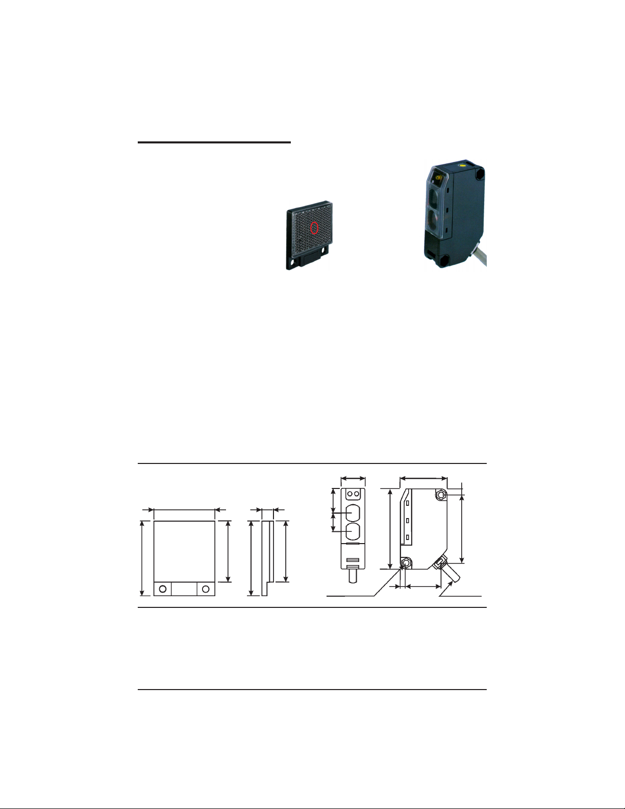
Dimensions:
2" (50mm)
Reflector
2" (50mm)
• Safety sensor for garage doors
or outdoor gates.
• Overhead door security sensor.
• Industrial automation
Detect small objects on a
manufacturing line.
• Entry detection for storefronts.
• Assist in measuring parking distance.
• Alarm sensor.
5/16" (8mm)
" (60mm)
8
/
3
2
2" (50mm)
--
13/16" (20mm)
13/16"
(20mm)
5/8"
(15.1mm)
2-Ø4.5 thru hole
ENFORCER
®
Includes:
••
• Reflector (E-931ACC-R)
••
••
• Transmitter/Receiver
••
(E-931-S35RRQ)
••
• Sensor mounting
••
bracket
(E-931ACC-BLS1)
••
• Reflector mounting
••
bracket
(E-931ACC-BLR1)
••
• Mounting hardware also
••
included.
15/8"
(40mm)
Sensor
" (66mm)
8
/
5
2
13/16"
(30mm)
3/16"
(5mm)
/16" (58mm)
5
2
Ø6 cable 2M
Caution:
• This sensor was not designed to prevent bodily injury
or loss of life.
• This sensor was not designed for use in
environments where there is the possibility of
explosive gasses present.
• Use of this sensor in certain security applications
may be regulated by local laws or codes.
SECO-LARM is not responsible for compliance with
such laws or codes.
Page 2
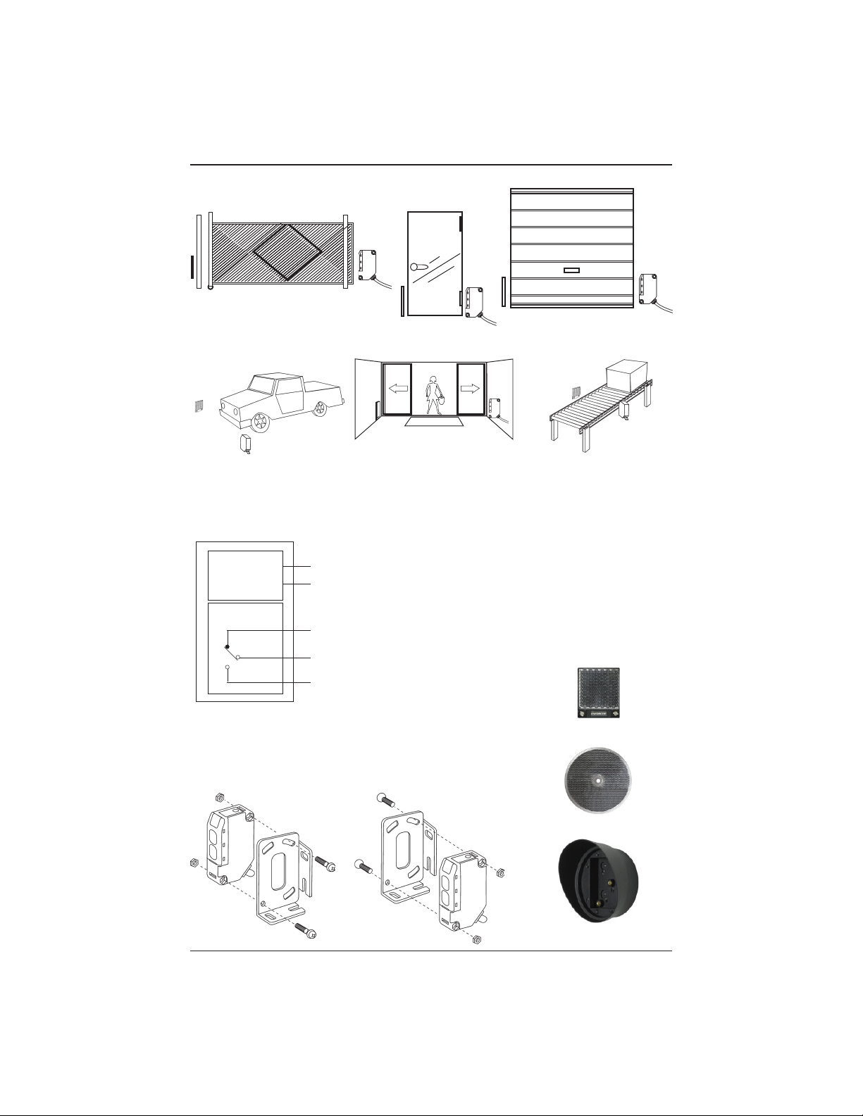
Sample Installations:
Gate
Gate
Gate
Gate
Gate
¤¤¤¤¤¤¤¤¤¤¤
Main
entrance
¤¤¤¤¤¤¤¤¤¤¤
door
¤¤¤¤¤
¤¤¤¤¤¤¤¤¤¤
¤¤¤¤¤
Garage
door
¤¤¤¤¤¤¤¤¤¤
Vehicle detection Factory assembly
¤¤¤¤¤¤¤¤
¤¤¤¤¤¤¤¤
Store front door
¤¤¤¤¤¤¤¤¤¤¤¤¤¤¤¤
W
m
c
o
e
e
l
¤¤¤¤¤¤¤¤¤¤¤¤¤¤¤¤
¤¤¤¤¤¤¤¤
Wiring:
Connection (5 wires)
Multi-voltage
circuit
Relay output
24-240VAC or
Brown
12-240VDC,
Blue
]
polarity not
important
Gray (N.C.)
White (COM)
Black (N.O.)
Note:
1. Can be connected to AC or DC voltage.
2. Maximum cable extension length is
325 feet (100 meters).
Accessories:
E-931ACC-R
line
¤¤¤¤¤¤¤¤
Mounting the Sensor:
E-931ACC-RC1Q
E-931ACC-HR1Q
2
Page 3

Mounting the Reflector:
Sample Fixed
Mounting:
Samples For Horizontally Adjusting
Mounting:
Installation and Adjustment:
LED Functions:
• Red LED -- When ON, it indicates the sensor is triggered.
• Yellow LED -- When ON, it indicates that the sensor is
properly aligned with the reflector, and the sensor is not
triggered.
Sensitivity Adjustment Functions:
• Min. Setting -- The infrared signal emitted by the sensor is at
its minimum or weakest. This means the sensor can be
easily triggered by small obstructing objects.
• Max. Setting -- The infrared signal emitted by the sensor is
at its maximum or strongest. This means the sensor cannot
be easily triggered by small obstructing objects.
Installation:
1. Mount the reflector and the sensor so they face each other.
2. Connect power to the sensor. Typically the red LED will turn
ON indicating that the sensor and reflector are not yet
properly aligned. If the yellow LED is ON (red LED OFF), it
indicates that the sensor and reflector are aligned (although
it still may be necessary to slightly adjust the alignment).
3. Turn the sensitivity knob to Max.
4. To find the correct alignment, slowly adjust the angles of the
sensor (and/or reflector) up and down and right and left.
NOTE 1: Correct alignment is reached when the red LED
turns OFF and the yellow LED turns ON.
NOTE 2: If both LEDs are OFF, the sensor is at the edge of
sensing the signal, and may not work properly.
Adjusting Sensitivity:
After the sensor and the reflector have been properly installed,
the next step is to adjust the sensor sensitivity.
1. Turn the sensitivity knob counterclockwise to “Min.”
2. Slowly turn the sensitivity knob clockwise until the yellow
LED turns ON. Mark this position “A”.
NOTE: If the yellow LED is ON when the sensitivity knob
has been adjusted to “Min.”, then position “A” will be at
“Min.”
Samples For Vertically Adjusting Mounting:
3. Put the object to be detected between the sensor and
reflector (in about the place where the object would
normally be detected by the sensor). The yellow LED
should turn OFF (red LED is ON)
4. Slowly turn the sensitivity knob to clockwise until the yellow
LED turns ON. Mark this position “B”.
NOTE: If the yellow LED does not turn ON even when the
sensitivity knob has been adjusted to “Max.” then position
“B” will be at “Max.”.
5. Turn the sensitivity knob counterclockwise until it is set at
the center (midpoint) between points “A” and “B”. This will
be the suggested sensitivity setting.
Testing:
1. Power up the sensor. The yellow LED should be ON; the
red LED should be OFF.
2. Pass the object to be detected between the sensor and
reflector. The red LED should turn ON and the yellow LED
should turn OFF. This indicates that the object has been
detected.
NOTE: If a shiny object, such as a chrome-plated or
stainless-steel item, or something with reflective tape, will
be passing between the sensor and reflector, the sensor
may not be able to detect it. In this case, it may be
necessary to turn the sensitivity knob counterclockwise
until the desired sensitivity setting is obtained.
Sensitivity
Adjuster
Red LED
Yellow
LED
3
Page 4

Specifications:
Model Number
Type
Sensing Range
Voltage Supply
Current Drain
Response Time
Light Source
LEDs
Trigger Output
Switching Capacity
Enclosure
Ambient Temperature
Mounting Brackets for Sensor and Reflector
Troubleshooting:
Trouble Remedy(s)Possible Origin(s)
Sensor does not detect the
object.
Yellow LED does not turn on.
Red LED lights when object
is detected, but no output.
1) Sensor sensitivity is not properly set.
2) Object may have a reflective surface
which confuses sensor.
1) Dirty sensor and/or reflector.
2) Reflector and/or sensor is
misaligned.
No continuity between sensor and
alarm device.
E-931-S35RRQ
Reflective Photoelectric Sensor
0.5' to 35' (0.1 - 11 m)
12-240 VDC or 24-240 VAC
Stand by Active
12VDC 20mA 40mA
24VDC 10mA 20mA
10ms (max.)
IR LED
Yellow LED (Alignment), Red LED (trigger)
N.O./N.C./Common
1A @ 50VAC
IP 66 Weatherproof
0
-4
~1310F (-200~550C)
Included
Change the angle of the sensor or
readjust the sensitivity setting.
1) Clean the sensor and reflector with
a damp (not wet) cloth.
2) Adjust the reflector and/or sensor
for proper alignment.
Check cable from sensor to alarm
device. Test sensor.
WARRANTY
service for a period of one (1) year from the date of sale to the original consumer customer. SECO-LARM’s obligation is
limited to the repair or replacement of any defective part if the unit is returned, transportation prepaid, to SECO-LARM.
This Warranty is void if damage is caused by or attributed to acts of God, physical or electrical misuse or abuse, neglect,
repair, or alteration, improper or abnormal usage, or faulty installation, or if for any other reason SECO-LARM determines
that such equipment is not operating properly as a result of causes other than defects in material and workmanship.
The sole obligation of SECO-LARM, and the purchaser’s exclusive remedy, shall be limited to replacement or repair only, at
SECO-LARM’s option. In no event shall SECO-LARM be liable for any special, collateral, incidental, or consequential
personal or property damages of any kind to the purchaser or anyone else.
NOTICE:
SECO-LARM policy is one of continual development and improvement. For this reason, SECO-LARM reserves the right
to change specifications without notice. SECO-LARM is also not responsible for misprints or typographical errors.
Copyright © 2013 SECO-LARM U.S.A., Inc. All rights reserved. This material may not be reproduced or copied, in whole
or in part, without the written permission of SECO-LARM.
This SECO-LARM product is warranted against defects in material and workmanship while used in normal
The information and specifications printed in this manual are current at the time of publication. However, the
SECO-LARM® U.S.A., Inc.
16842 Millikan Avenue, Irvine, CA 92606
Tel: 800-662-0800 / 949-261-2999 Fax: 949-261-7326
Website: www.seco-larm.com
@
E-mail: sales
seco-larm.com
NIRmUd.PMD
 Loading...