

Page 1
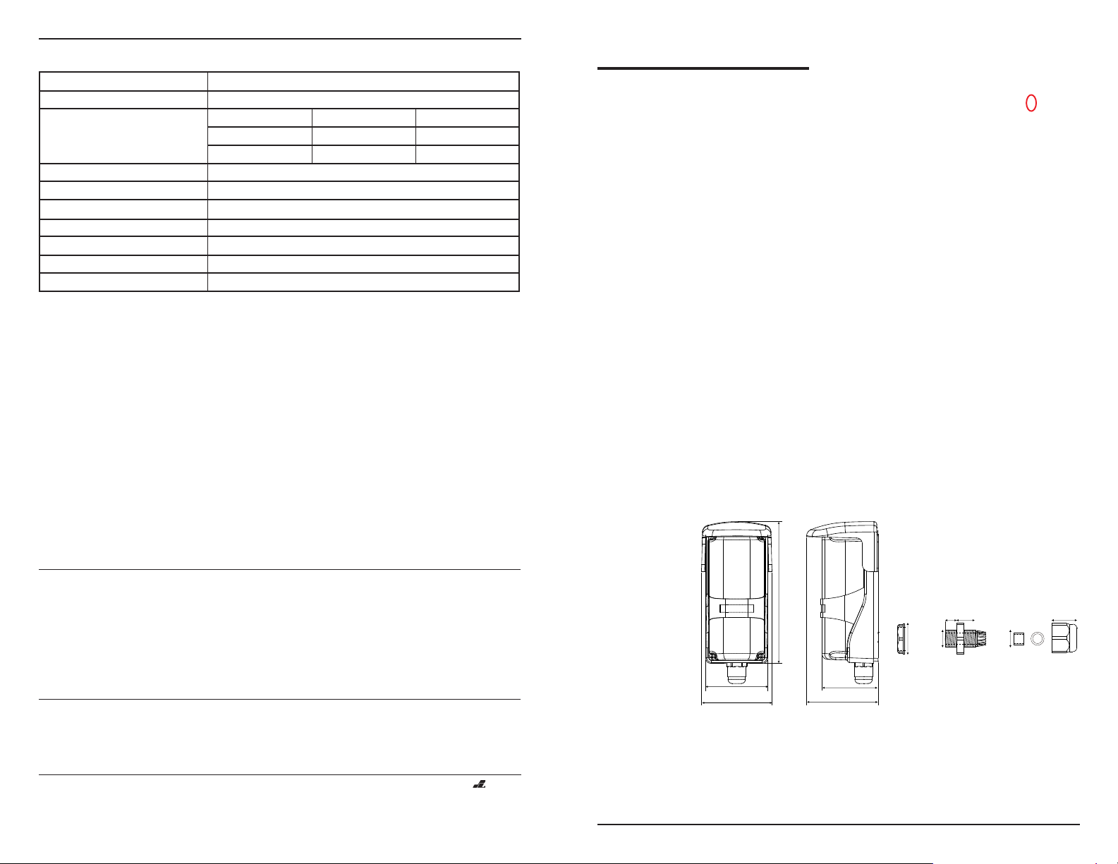
Specifications:
13
4/" (122mm)
16
3
2 /" (53mm)
32
13
2/" (61mm)
32
7
2 /" (62mm)
16
15
2/" (49mm)
16
5/8(16mm)
5/16”
(8mm)
9/16”
(14mm)
5/16”
(8mm)
1/4”
(6mm)
17/32”
(13 4mm)
Sensing range
Voltage supply
Current drain (max.)
12 VDC
24 VDC
Response time
Tx LED element
LEDs
Trigger output
SPDT relay output, 1 A @ 125 VAC, 2 A @ 30 VDC
Tamper switch
Enclosure
Ambient temperature
Also available from SECO-LARM:
Quad and Twin
Photobeam Detectors
Up to 660' (200 m)
Flush-Mount
Photobeam Sensors
Up to 33' (10 m)
E-932-D33TBQ
0.5' to 33' (0.1 - 10 m)
12~250 VAC/DC
Stand by
20 mA
10 mA
Active
40 mA
20 mA
10 ms (max.)
Infrared - 740 nm
Green LED (Alignment), Red LED (trigger)
N.C., 500 mA @ 30 VAC
IP 66 weatherproof
-40~1310 F (-200~550 C)
Entry Alert System
Photobeam Sensors
Up to 22' (7 m)
ENFORCER
Sensor
Polarized Retro-Reflective
Photoelectric Sensor
E-931-S33PRQ
Range: 33 ft. (10 m)
INSTALLATION MANUAL
Features:
•
• Polarized sensor is immune to shiny
objects: Triggers only when correctly
reflected light is detected.
• Weatherproof (IP 66) design with
cable gasket for indoor/outdoor use.
• Anti-condensation case.
•
• Dark ON operation.
• Round reflector, Dia.: 80 mm.
• Input volt.: 12-250 VDC/VAC.
• Form "C" relay, 2A @ 30 VDC.
• LED alignment system.
• Tamper switch: N.C. 500 mA @ 30 VDC.
Typical Applications:
• Safety sensor for garage doors,
outdoor gates, or sliding doors.
• Overhead door security sensor.
• Industrial automation
Detect small objects on a
manufacturing line.
• Assist in measuring parking distance.
• Alarm sensor for windows, terraces,
parking lot, etc.
ЮЮЮЮЮЮ
ЮЮЮЮЮЮ
Includes:
• Reflector
• Sensor
• Sensor mounting plate
•
--
• Weather-resistant gasket
•
• Sensor hood
•
E-931CS22RRCQ
E-964-Q660Q
(Shown)
WARRANTY
service for a period of one (1) year from the date of sale to the original consumer customer. SECO-LARM’s obligation is
limited to the repair or replacement of any defective part if the unit is returned, transportation prepaid, to SECO-LARM.
This Warranty is void if damage is caused by or attributed to acts of God, physical or electrical misuse or abuse, neglect,
repair, or alteration, improper or abnormal usage, or faulty installation, or if for any other reason SECO-LARM determines
that such equipment is not operating properly as a result of causes other than defects in material and workmanship.
The sole obligation of SECO-LARM, and the purchaser’s exclusive remedy, shall be limited to replacement or repair only, at
SECO-LARM’s option. In no event shall SECO-LARM be liable for any special, collateral, incidental, or consequential
personal or property damages of any kind to the purchaser or anyone else.
NOTICE:
SECO-LARM policy is one of continual development and improvement. For this reason, SECO-LARM reserves the right
to change specifications without notice. SECO-LARM is also not responsible for misprints or typographical errors.
Copyright © 2010 SECO-LARM U.S.A., Inc. All rights reserved. This material may not be reproduced or copied, in whole
or in part, without the written permission of SECO-LARM.
SECO-LARM® U.S.A., Inc.
16842 Millikan Avenue, Irvine, CA 92606
Tel: 800-662-0800 / 949-261-2999 Fax: 949-261-7326
This SECO-LARM product is warranted against defects in material and workmanship while used in normal
The information and specifications printed in this manual are current at the time of publication. However, the
E-932-S16RRQ
Website: www.seco-larm.com
E-mail: info@seco-larm.com
MiE931-S33PROQ_1012.PMD
®
PITSW3
Dimensions:
Caution:
• This sensor was not designed to prevent bodily injury
or loss of life.
• This sensor was not designed for use in
environments where there is the possibility of
explosive gasses present.
• Use of this sensor in certain security applications
may be regulated by local laws or codes.
SECO-LARM is not responsible for compliance with
such laws or codes.
Page 2
1
2
3
4
5
6
7
AC/D
2~ 50
NC O COM T1 T 2
(N n poai y)
1
2
3
4
5
6
7
AC/DC
1
2~250V
NC NO COM TP1 TP2
(Non polarity)
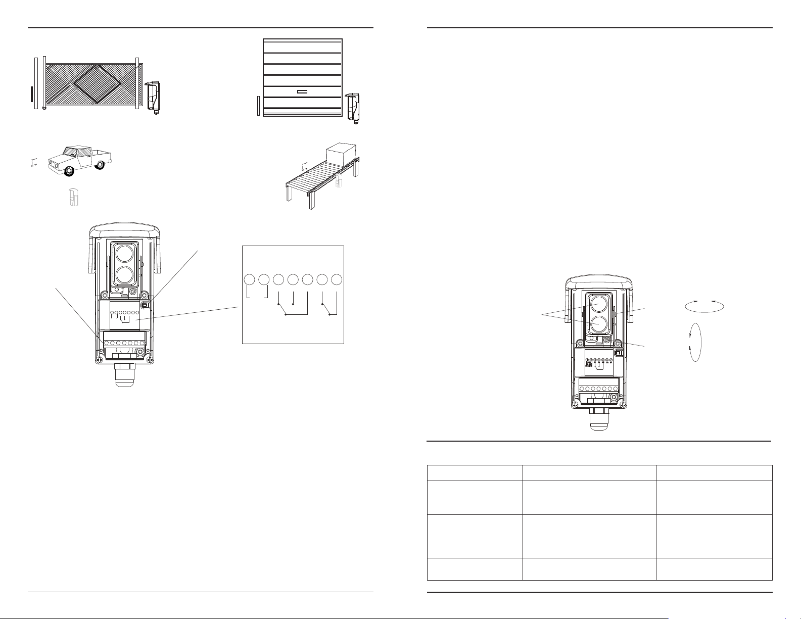
Sample Installations:
Gate
ЮЮЮЮЮЮЮЮЮЮЮ
Vehicle detection
ЮЮЮЮЮЮ
ЮЮЮЮЮЮ
Wiring:
Removeable
Terminal
Blocks
ЮЮЮЮЮЮЮЮЮЮЮ
N.C.
Tamper
Switch
Garage
door
ЮЮЮЮЮЮЮЮЮ
Factory assembly line
ЮЮЮЮЮЮ
ЮЮЮЮЮЮ
Installation and Adjustment:
Dual-Color LED Functions:
• Red LED - - When ON, it indicates the sensor is
ЮЮЮЮЮЮЮЮЮ
• Green LED - - When ON, it indicates that the sensor is
• LED alternately flashes red and green - - Sensor beam
Installation:
1. Mount the reflector and the sensor so they face each
2. Connect power to the sensor. Typically the red LED
3. To find the correct alignment, slowly turn the lens
triggered.
properly aligned with the reflector, and the sensor is
not triggered.
signal is weak (not triggered).
other.
will turn ON indicating that the sensor and reflector
are not yet properly aligned. If the Green LED is ON
(red LED OFF), it indicates that the sensor and
reflector are aligned (although it still may be
necessary to slightly adjust the alignment).
Lens
Assembly
assembly left and right, and use the vertical
adjustment screw to tilt the sensor up and down.
NOTE 1: Correct alignment is reached when the red
LED turns OFF and the Green LED turns ON.
NOTE 2: If the LED alternately flashes green and
red, the sensor is at the edge of sensing the signal,
and may not work properly.
4. Put the object to be detected between the sensor
and reflector (in about the place where the object
would normally be detected by the sensor). The
green LED should turn OFF and the red LED will turn
ON).
Testing:
1. Power up the sensor. The green LED should be ON;
the red LED should be OFF.
2. Pass the object to be detected between the sensor
and reflector. The red LED should turn ON and the
green LED
should turn OFF. This indicates that the object
has been detected.
Horizontal
±90°
Adjustment
Mounting the Sensor:
Additional function:
TP1/TP2 - Tamper Switch:
N.C. 500 mA @ 30 VDC
1. Unscrew the 4 screws and remove the cover.
2. Loosen the captive screw to free the sensor from
the mounting plate.
3. Using the included screws, mount the mounting
plate to the wall.
4. If the wires come from inside the wall, use the
breakout and rubber gasket on the back of the
sensor to run the wires. If not, use the breakout
and cable gland at the bottom of the sensor to run
the wires.
5. Remove the terminal block using long-nose pliers
and wire the unit according to the wiring diagram
above.
6. Hang the sensor back on to the plate, and use the
captive screw to secure it in place.
7. Re-attach the cover, and use the included small
screws to secure it.
8. Attach the hood to the top of the sensor.
2
Troubleshooting:
Trouble Remedy(s)Possible Origin(s)
Sensor does not detect the
object.
Green LED does not
turn on.
Red LED lights when object
is detected, but no output.
1) Sensor sensitivity is not properly set.
2) Object may have a reflective surface
which confuses sensor.
1) Dirty sensor and/or reflector.
2) Reflector and/or sensor is
misaligned.
No continuity between sensor and
alarm device.
Vertical
Adjustment
±5°
Change the angle of the sensor or
readjust the sensitivity setting.
1) Clean the sensor and reflector
with a damp (not wet) cloth.
2) Adjust the reflector and/or
sensor for proper alignment.
Check cable from sensor to alarm
device. Test sensor.
3
 Loading...