

Page 1
VOICE DIALER Installation Manual
CHECKING THE STATUS OF SENSORS
The "TEST" mode can be used to check the current status of both sensors during
installation. Press the "MODE" button and select the "TEST" mode. The status of both
sensors will be simultaneously shown on the LCD.
a. S1-O: Indicates the relay contact of sensor #1 is "OPEN".
b. S1-C: Indicates the relay contact of sensor #1 is "CLOSED".
c. S2-O: Indicates the relay contact of sensor #2 is "OPEN".
d. S2-C: Indicates the relay contact of sensor #2 is "CLOSED".
Installation Manual
®
ENFORCER
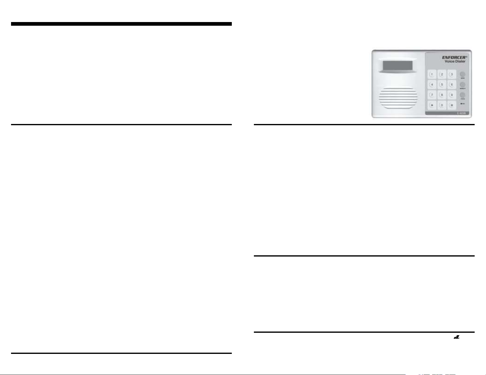
E-920B
Voice Dialer
Summary: The E-920B Voice Dialer
will automatically dial up to four
telephone numbers and deliver one
of two different messages when
triggered by an alarm system.
TESTING THE UNIT — DIALING OUT TO THE PROGRAMMED
NUMBERS
Note: To ensure proper operation, the E-920B must be tested at least once in the
OPERATE mode, and the dialer must be connected to the phone line.
1. Contact the company or person who
will be called by each of the recorded
telephone numbers prior to performing
an actual test in the "OPERATE" mode.
Advise the people at the numbers
dialed that you are conducting a test,
and ask them to confirm with you that
the message was received and
understood.
2. Turn the power "OFF".
3. Connect the dialer to the phone line
(see page 3).
4. The sensor should not be in the alarm
mode. If it is, the unit will start dialing
immediately.
5. Turn the power "ON".
6. Use the "MODE" button to place the
unit in the "OPERATE" mode.
Note: Prior to operation of the E-920B, be sure the power source is correct and the
wiring is connected properly. It is recommended that the E-920B be tested under
simulated alarm conditions and that the user receive confirmation of transmission
from the numbers dialed.
7. Trigger input #1 or #2 to simulate an
alarm condition.
8. At this point the dialer should begin
to dial the telephone numbers #1 to
#4. The outgoing message (1 or 2,
depending on which trigger is
tripped) will be delivered for one
minute once the dialer makes a
connection.
Note: The message will not be heard
because the test is just a controlled
alarm event.
9. The message will repeat for #2, #3
and #4 telephone numbers. If a
number is busy or unanswered after
8 to 10 rings, that number will be
skipped, and dialed again once the
other numbers have finished dialing.
Numbers that are still busy will be
dialed a third and final time.
SECO-LARM U.S.A., Inc.Page 8
HOW IT WORKS
When triggered by an alarm system, the
E-920B Voice Dialer can dial up to four
telephone numbers and/or pager numbers.
Each number can contain up to 32 digits
(including pound (#) tones and pauses
used in pager numbers).
When the dialer is activated, the LCD will
show the numbers dialed at each step of
the dialing process. When the dialer
makes a connection, one of two possible
16-sec. voice messages will be delivered.
The user can record each message to
respond to one or two inputs. Each
message is then delivered repeatedly for
one minute to ensure the full message is
received. This process will repeat for each
number stored.
If within 8 to 10 rings there is no
connection, the E-920B will automatically
dial the next programmed number.
If the dialer has attempted to dial each
number one time and the unit is still in the
alarm state, the dialer will attempt to call
all numbers a second time. All busy
numbers will be dialed a third time.
Note: If the dialer is programmed to call
a voice pager service which requires
operator assistance, the service should
be notified in advance regarding the
meaning of the message.
WARRANTY: This SECO-LARM product is warranted against defects in material and workmanship
while used in normal service for a period of one (1) year from the date of sale to the original consumer customer.
SECO-LARM’s obligation is limited to the repair or replacement of any defective part if the unit is returned,
transportation prepaid, to SECO-LARM.
This Warranty is void if damage is caused by or attributed to acts of God, physical or electrical misuse or abuse,
neglect, repair, or alteration, improper or abnormal usage, or faulty installation, or if for any other reason
SECO-LARM determines that such equipment is not operating properly as a result of causes other than defects
in material and workmanship.
The sole obligation of SECO-LARM, and the purchaser ’s exclusive remedy, shall be limited to replacement or
repair only, at SECO-LARM’s option. In no event shall SECO-LARM be liable for any special, collateral,
incidental, or consequential personal or property damages of any kind to the purchaser or anyone else.
SECO-LARM® U.S.A., Inc.
16842 Millikan Avenue, Irvine, CA 92606
Tel: 800-662-0800 / 949-261-2999 Fax: 949-261-7326
MiE920B_0910.pmd
Website: www.seco-larm.com
E-mail: sales
@
PIKVR1
seco-larm.com
Page 1
Page 2
VOICE DIALER Installation Manual
VOICE DIALER Installation Manual
TABLE OF CONTENTS
How It Works ........................................... 1
E-920B Overview ...................................... 2
Wiring Diagram ......................................... 3
Connecting the E-920B ............................3
Setting the DIP Switches .......................... 4
Storing Telephone Numbers .....................5
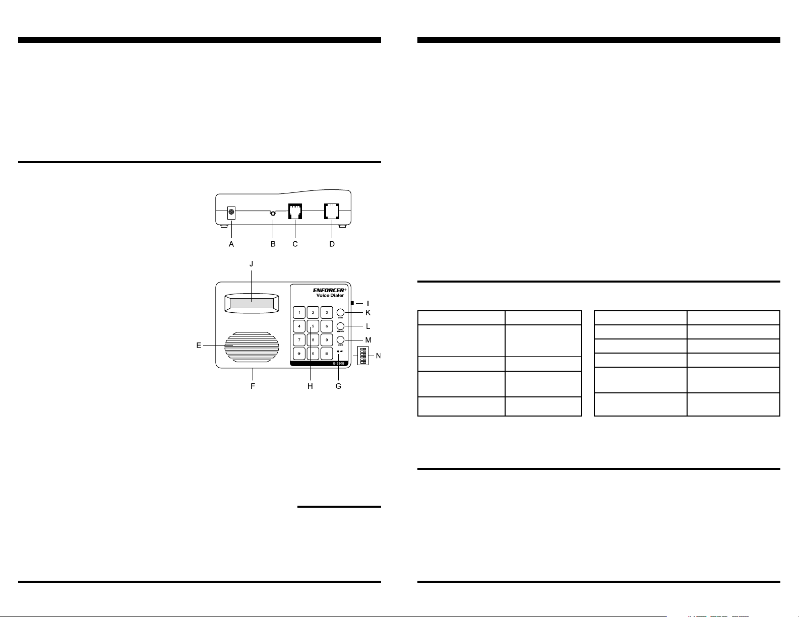
E-920B OVERVIEW
A. DC adapter jack
B. Siren output jack
C. Sensor input connector
D. Telephone line connector
E. Speaker
F. 9VDC battery compartment
G. Microphone
H. Dial keys
I. Power switch
J. LCD display
K. MODE button — 3 selections:
1. PROGRAM — Telephone no. and
voice message recording
2. CHECK STATUS — Status of
inputs #1 & #2
3. OPERATE— Armed condition
L. MEMORY button — For recording
and erasing telephone no.
M. VOICE button — For recording and
playing voice messages.
N. DIP Switches:
1. Exit delay 1 or 120 secs. (Beeps
once every second during exit time
delay)
2. Entrance delay (1 or 30 secs.)
3. Tone/pulse telephone
4. Trigger input #1 and #2 timing
5. NO or NC input #1
6. NO or NC input #2
Recording Messages ................................6
Erasing Memory ....................................... 6
Storing Pager Numbers & Access Codes 6
Specifications ........................................... 7
Checking the Status of Sensors ............... 8
Testing the Unit — Operate Mode ............8
Parts List
Manual x 1
Wall bracket x 1
Screws x 2
Telephone cable x 1
4-Pin connector x 1
Note: The telephone numbers can be programmed in any order, and skipped as
needed. Whenever a new telephone number is programmed, it will completely
erase and replace old telephone numbers previously stored in that location.
Example 1: Store pager number 585-8525 and numeric message 119 as telephone #3.
Press: 5 8 5 8 5 2 5, "MEMORY" (hold two sec.), 1 1 9, "MEMORY" (momentarily), 3
Example 2: Store pager number 585-8525 with access code 3 (if required) and numeric
message 119 as telephone #4.
Press: 5 8 5 8 5 2 5, "MEMORY" (hold two sec.), 3 (access code), #, 1 1 9,
"MEMORY" (momentarily), 4
Example 3: Store pager number 1-818-585-8525 with access code 2 (voice message
code) as telephone #3.
Press: 1 8 1 8 5 8 5 8 5 2 5, "MEMORY" (hold two sec.), 2, * , "MEMORY"
(momentarily), 3
SPECIFICATIONS
Operating Voltage
Current Draw
Trigger Inputs
Operating Temp.
Backup Battery
*With siren connected. Siren output 180mA maximum.
12VDC
40mA (standby)
60mA (active)
250mA (siren active)*
2 NO/NC
-4°~122°F
(-20°~50°C)
9VDC (not included)
No. of Tel. #s Stored
Max. Digits Per Tel. #
Case Material
Weight
Dimensions
Warranty
Up to 4
32
ABS plastic
11-oz (320g)
7
5
/8"x4"x1½"
(148x100x39 mm)
1 Year
NOTICE
The information and specifications printed in this manual are current at the time of
publication. However, the SECO-LARM policy is one of continual development and
improvement. For this reason, SECO-LARM reserves the right to change specifications
without notice. SECO-LARM is also not responsible for misprints or typographical errors.
Copyright © 2009 SECO-LARM U.S.A., Inc. All rights reserved. This material may not be
reproduced or copied, in whole or in part, without the written permission of SECO-LARM.
SECO-LARM U.S.A., Inc.Page 2
Page 7
Page 3

VOICE DIALER Installation Manual
VOICE DIALER Installation Manual
RECORDING OUTGOING VOICE MESSAGE(S)
The E-920B can play back one of two
outgoing messages of up to 16 seconds
each:
• Message one is played when input #1
(yellow wire) is triggered.
• Message two is played when input #2
(green wire) is triggered.
To ensure the message is received, each
message is repeated for one minute.
Both outgoing messages should be
timed and practiced prior to recording.
To record the outgoing voice message(s):
1. Locate the microphone in the lower
right corner of the keypad area. When
recording a message, speak in a
normal voice about 7 inches from the
microphone.
2. Place the unit in the "PROGRAM" mode
by pressing the "MODE" button.
3. Press key "1" to specify the first voice
message, or press key "2" to specify
the second message.
4. To record, press and hold the "VOICE"
button. The word "VOICE" will appear
on the LCD during recording. The
"VOICE" button must be held down for
the entire time of the recording.
5.
As soon as the voice key is released
or when 16 secs. have passed, the
word "VOICE" will disappear from the
LCD. This indicates that the message
is stored.
6. If you wish to change either outgoing
message, repeat steps 1 through 5.
The previous message will be
replaced when the new message is
recorded.
7. Once recorded, review the voice
message simply by pressing the
"VOICE"
play. Pressing
the second message. To review at
other times, first press the "MODE"
button until "PROGRAM" shows on the
LCD. Pressing
replay message one and two.
button. The first message will
"VOICE"
"VOICE"
again will play
will alternately
TO COMPLETELY ERASE NUMBERS STORED IN MEMORY
1. Press the "MODE" button to set the
dialer to "PROGRAM" mode.
2. Press the "MEMORY" button.
3. When the LCD indicates telephone
numbers, press "#".
4. Test the unit once again. (see pg. 8)
TO STORE A PAGER NUMBER AND/OR NUMERIC CODE
1. Press the "MODE" button to set the
dialer to "PROGRAM" mode.
2. Enter the pager number to be dialed
including any area code if necessary.
Check to see that the correct number
is displayed by the LCD.
3. Press and hold the "MEMORY" button
for about two seconds. A "dash" will
appear on the LCD to indicate that the
dialer will pause approx. five secs., to
allow the pager time to respond.
Note: Pauses and "#" keys count as
one digit. Each number stored can
contain up to 32 digits.
4. Input the numeric code desired for the
pager directly after the pause (this
number will appear on the pager unit).
Input a "#" at the end of the message if
required by the pager service (may not
be necessary).
5. Momentarily press the "MEMORY"
button and then the "1" key. The pager
number and numeric code will be
stored as telephone #1.
6. Repeat for telephone #2, #3, and #4 if
needed.
SECO-LARM U.S.A., Inc.Page 6
WIRING DIAGRAM
2. 1x5 .5x 9 mm
12VDC center
positive plug
Note: If the red
wire is connected
to the alarm
control panel's
+12VDC output,
the adapter is
optional.
12VDC
adapter
(not included)
Siren output jack.
2.5mm mono jack.
Transistor ground
output 180mA
A
B
ma xim um.
CONNECTING THE E-920B
Note: You can program telephone
numbers and voice messages prior to
connecting power as long as the 9VDC
battery is installed. The standby battery
will allow for about 24 hours of
operation.
Note: The E-920B uses an EEPROM to
retain memory in the event of a power
loss.
1. Select a location for the dialer that is
near both an AC outlet and the alarm
control panel. Keep the E-920B out of
sight.
2. Connect to power:
a. If the dialer is powered from the alarm
control panel, connect the red, black,
yellow, and green wires of the 4-pin
connector to the panel as shown in
the wiring diagram.
b. If using an optional 12VDC adapter, it
is not necessary to connect the red
wire of the 4-pin connector to the
alarm control panel. However, the
black, yellow, and green wires MUST
be connected.
RED (+12VDC ONLY) (optional)
BLACK (common (-) ground, must connect)
YELLOW (trigger 1, message 1) NO/NC* (GND)
GREEN (trigger 2, message 2)
RED
GREEN
(not included)
9VDC
c. For more reliable power, connect
both the red wire and a 12VDC
adapter (not included). For backup
power, also install a 9VDC battery
(not included).
3. The two inputs can be connected to two
separate alarm control panel outputs.
Each input triggers a specific voice
message. The yellow wire (input #1) is
for the first voice message, and the
green wire (input #2) is for the second
voice message. The messages should
reflect the type of emergency which the
alarm's output represents. The green
and yellow wires should be connected
to separate NO or NC outputs of the
alarm.
4. The dialer can be connected to a pulse
or touch-tone phone line using the
included telephone cable.
5. Once all connections have been made,
the unit is ready to be programmed.
NO/NC* (GND)
*Based on DIP switch
See page 4, Sections 5 & 6
Telephone line
(must connect when
testing dialer)
OPTIONAL
ACCESSORIES
A. 12VDC adapter
B. 9VDC standby battery
Page 3
Page 4

VOICE DIALER Installation Manual
VOICE DIALER Installation Manual
SETTING THE DIP SWITCHES
1. DIP SWITCH #1 — EXIT DELAY TIME (Default ON)
a. ON (1 second) — When set to the OPERATE mode, the E-920B will dial the
programmed numbers immediately when triggered.
b. OFF (DELAY) — When set to the OPERATE mode, the E-920B will allow 120
seconds to pass before it can be triggered. This gives the user time to leave
the protected premises without triggering the voice dialer.
2. DIP SWITCH #2 — ENTRANCE DELAY TIME (Default ON)
a. ON (1 second) — When triggered while in the OPERATE mode, the E-920B
will immediately dial the programmed number (after any exit delay has
passed).
b. OFF (DELAY) — When triggered while in the OPERATE mode, the E-920B will
wait 30 seconds after being triggered before dialing the programmed numbers.
This gives the user time to turn off the E-920B before the voice dialer triggers
when entering a protected premises.
Note: Unless the user requires extra time, if the E-920B is being used with an
alarm panel which has a programmed entry/exit delay, both DIP switches
#1 and #2 should be placed in the "ON" position, which provides an instant
response to any trigger.
3. DIP SWITCH #3 — TELEPHONE DIALING TYPE (Default OFF)
a. ON — Pulse/rotary phone
b. OFF — Touch-tone phone
4. DIP SWITCH #4 — INPUT #1 AND #2 TIMING (Default ON)
Timing for input #1 and input #2 function the same way.
a. ON — The E-920B will dial all programmed telephone numbers two times when
triggered by input #1 or input #2, regardless of whether the input signal (from
the alarm control panel) is reset or not. This function also works with any nontimed (momentary) input device.
b. OFF — If the triggered input is reset, the dialing action stops. If used with
input devices other than an alarm control panel with timed outputs, a timer may
be required.
5. DIP SWITCH #5 — NO or NC input #1 (Default ON)
a. ON — Use NO type device to trigger input #1
b. OFF — Use NC type device to trigger input #1
6. DIP SWITCH #6 — NO or NC input #2 (Default ON)
a. ON — Use NO type device to trigger input #2
b. OFF — Use NC type device to trigger input #2
STORING PHONE NUMBERS
The E-920B will dial up to four separate
telephone numbers when triggered by
one of two different inputs. These
numbers can be used to call a telephone,
cell phone, or pager.
Note: Consult local authorities
regarding the legality of automatically
dialing their telephone numbers prior to
programming.
Each of the four telephone numbers can
be programmed for up to 32 digits
(including pound (#) tones and pauses
used in pager numbers). The unit will
automatically skip any telephone
numbers left blank. If there are fewer
than four telephone numbers to be
dialed, do not enter numbers in the
uneeded locations, or clear numbers
previously stored there.
INSTRUCTIONS FOR STORING TELEPHONE #1 --- #4
1. Turn the power switch "ON".
2. The LCD of the E-920B will indicate
which mode the unit is in (PROGRAM,
TEST, or OPERATE). Press the
"MODE" button to select the
"PROGRAM" mode.
Note: If using a PBX phone system,
press the dial-out code, then the #
key, followed by the phone number
to be called when the pause signal
is displayed on the LCD.
3. Enter the telephone number to be
dialed, including any area code if
necessary. Check to see that the
correct number is displayed by the
LCD.
4. Momentarily press the "MEMORY"
button after the entire phone number
has been entered, then press the "1"
key. This number is now telephone #1.
Note: The telephone numbers can be programmed in any order, and skipped as
needed. Whenever a new telephone number is programmed, it will completely
erase and replace old telephone numbers previously stored in that location.
Example 1: Store telephone number 582-6191 as #4.
Press: 5 8 2 6 1 9 1, MEMORY (momentarily), 4
Example 2: Store telephone number: 1-222-585-8525 as #2.
Press: 1 2 2 2 5 8 5 8 5 2 5, MEMORY (momentarily), 2
Example 3: Using a PBX phone system, store telephone number: 555-1234 as #3.
Press: 9 # 5 5 5 1 2 3 4, MEMORY (momentarily), 3
5. For telephone #2, input all the digits
for the second number to be dialed,
momentarily press the "MEMORY"
button, then the "2" key.
6. Repeat this process for telephone #3
and #4, if needed.
7. To check the numbers, enter
"PROGRAM" mode and press the
"MEMORY" button. Pressing "MEMORY"
again will show the next number.
Stored numbers will be displayed in
sequence.
8. When done programming, exit the
"PROGRAM" mode by pressing the
"MODE" button to go to the "OPERATE"
or "TEST" mode.
SECO-LARM U.S.A., Inc.Page 4
Page 5
 Loading...